EP1488965A1 - Vorrichtung zur Auslösung eines schnell beweglichen Bauteiles - Google Patents
Vorrichtung zur Auslösung eines schnell beweglichen Bauteiles Download PDFInfo
- Publication number
- EP1488965A1 EP1488965A1 EP03013633A EP03013633A EP1488965A1 EP 1488965 A1 EP1488965 A1 EP 1488965A1 EP 03013633 A EP03013633 A EP 03013633A EP 03013633 A EP03013633 A EP 03013633A EP 1488965 A1 EP1488965 A1 EP 1488965A1
- Authority
- EP
- European Patent Office
- Prior art keywords
- lever
- holding position
- locking lever
- locking
- movement
- Prior art date
- Legal status (The legal status is an assumption and is not a legal conclusion. Google has not performed a legal analysis and makes no representation as to the accuracy of the status listed.)
- Granted
Links
- 230000001960 triggered effect Effects 0.000 claims description 13
- 238000009434 installation Methods 0.000 description 3
- 238000004880 explosion Methods 0.000 description 2
- 210000003746 feather Anatomy 0.000 description 2
- 230000035939 shock Effects 0.000 description 2
- 241000511343 Chondrostoma nasus Species 0.000 description 1
- 229910000831 Steel Inorganic materials 0.000 description 1
- 235000010716 Vigna mungo Nutrition 0.000 description 1
- 244000042295 Vigna mungo Species 0.000 description 1
- 230000005540 biological transmission Effects 0.000 description 1
- 230000000903 blocking effect Effects 0.000 description 1
- 230000001419 dependent effect Effects 0.000 description 1
- 230000000881 depressing effect Effects 0.000 description 1
- 239000002655 kraft paper Substances 0.000 description 1
- 239000003973 paint Substances 0.000 description 1
- 230000036316 preload Effects 0.000 description 1
- 230000002441 reversible effect Effects 0.000 description 1
- 239000010959 steel Substances 0.000 description 1
Images


Classifications
-
- B—PERFORMING OPERATIONS; TRANSPORTING
- B60—VEHICLES IN GENERAL
- B60R—VEHICLES, VEHICLE FITTINGS, OR VEHICLE PARTS, NOT OTHERWISE PROVIDED FOR
- B60R21/00—Arrangements or fittings on vehicles for protecting or preventing injuries to occupants or pedestrians in case of accidents or other traffic risks
- B60R21/34—Protecting non-occupants of a vehicle, e.g. pedestrians
-
- B—PERFORMING OPERATIONS; TRANSPORTING
- B60—VEHICLES IN GENERAL
- B60R—VEHICLES, VEHICLE FITTINGS, OR VEHICLE PARTS, NOT OTHERWISE PROVIDED FOR
- B60R21/00—Arrangements or fittings on vehicles for protecting or preventing injuries to occupants or pedestrians in case of accidents or other traffic risks
- B60R21/02—Occupant safety arrangements or fittings, e.g. crash pads
- B60R21/13—Roll-over protection
- B60R2021/132—Roll bars for convertible vehicles
- B60R2021/134—Roll bars for convertible vehicles movable from a retracted to a protection position
- B60R2021/135—Roll bars for convertible vehicles movable from a retracted to a protection position automatically during an accident
-
- B—PERFORMING OPERATIONS; TRANSPORTING
- B60—VEHICLES IN GENERAL
- B60R—VEHICLES, VEHICLE FITTINGS, OR VEHICLE PARTS, NOT OTHERWISE PROVIDED FOR
- B60R21/00—Arrangements or fittings on vehicles for protecting or preventing injuries to occupants or pedestrians in case of accidents or other traffic risks
- B60R21/34—Protecting non-occupants of a vehicle, e.g. pedestrians
- B60R21/38—Protecting non-occupants of a vehicle, e.g. pedestrians using means for lifting bonnets
Definitions
- the invention relates to a device for triggering fast moving Components, in particular safety components, according to the preamble of the claim 1.
- DE 198 21 594 A1 shows a device for triggering a roll bar of a convertible vehicle in the event of a rollover. This includes three pivoting levers supported against each other in the holding position. It must be ensured be that an unwanted triggering, such as shocks when driving over potholes, is excluded, but on the other hand the required release force and the required release path for the device so is as small as possible in order to keep the triggering actuator small and light and to be able to set the release speed as high as possible.
- the invention has for its object to a device of the type mentioned improve.
- the invention solves this problem by a device with the features of Claim 1, by a device with the features of claim 14 and of claim 15 and claim 16, individually or in combination can be trained.
- a device with the features of claim 14 and of claim 15 and claim 16 individually or in combination can be trained.
- a torque further lever unloaded arrangement of the operating lever in the holding position ensures that the triggering actuator, such as an electromagnet, is not against one must work on such torque.
- the actuator can therefore be smaller and Easier training and short travel distance ensure a quick release.
- the locking lever is supported or an intermediate lever self-stabilizing, so that an unwanted Triggering is reliably excluded.
- the locking member is in the holding position indirectly via one or more Intermediate lever or supported directly on the actuating lever in such a way that a force oriented in the plane of its axis of rotation acts on it, a torque on the operating lever can be reliably avoided.
- the force is then applied to the center of the axis of rotation, so that none Total torque on this lever results.
- a very vibration and shock resistant training results when the locking member is formed by a pivot lever, which is in the holding position a pivotable intermediate lever blocking the movement of the locking member supported on the operating lever.
- the device is reversible from the release position into the holding position possible by mechanical pressure on the levers, which through this Pressure to be put back into the stop position so that the difference for explosion-triggered tripping, the cost of triggering an inventive Device are small.
- a modular design according to claim 14 ensures that the assembly costs can be kept low.
- the reliability of the device thereby increases that the position of the triggering lever and the spring-loaded Unit must not be adjusted against each other during installation, but the completely set up and adjusted module can be assembled in the Motor vehicle are used.
- the prestressed Module when installing the prestressed Module the risk of a false trigger compared to one only during installation reduced to exciting spring.
- the device 1 shown in FIG. 1 shows a partial area 2 of a when triggered fast moving unit, such as one that can be moved upwards in the event of a crash Bonnet, a roll bar that can be extended in a translatory or rotary manner, an active headrest, a seat or headrest adjustment, an active Bumper or similar component or assembly. From this one is here only one with a holding part 3, such as a pin, stub axle or the like, provided lever 4 shown.
- the lever 4 is by at least one strong spring 5, here a coil spring, or another drive biased in the sense of release, so that a large force 6 acts on the holding part 3 in the triggering direction.
- the holding part 3 is in the holding position shown in a mouth 7 of a locking member, here as a locking lever 8 which can be pivoted about an axis 9 is trained. Since the Haiteteilability 7 close to the axis of rotation 9 lies (lever arm 10), despite the great attacking force 6 that on the Locking lever 8 acting torque relatively low. The high power 6 the spring 5 is required for rapid movement of the assembly, such as one Roll bar to ensure in the event of a crash.
- the support takes place in such a way that from the intermediate lever 13 into the actuating lever 17 initiated force 18 in the direction of the axis of rotation 19 of the actuating lever 17 points and therefore does not exert a resulting torque on it.
- the force 18 of the intermediate lever 13 results from that exerted by the spring 5 Torque on the locking lever 8 by this as another Torque is transmitted to the intermediate lever 13.
- the direction of it resulting force 18 lies in one plane with the axis of rotation 19 of the actuating lever 17.
- the opposite the force application point with respect to the axis 19 located free end 20 of the operating lever 17 forms a lever arm 21, via which the actuator 16 pivots the actuating lever in the holding position 17 prevents and acts on this to trigger.
- the actuator 16 works against the friction torque that results from the force 18 and the lever arm between the Force application point of the force 18 and the axis of rotation 19 of the actuating lever 17 results against the frictional torque in the axis of rotation 19 and possibly against the restoring force a spring 31 (see e.g. Fig. 10).
- the spring 31 can usually Replace return spring (not shown) located in an actuator 16.
- the locking lever 8, the intermediate lever 13 and the operating lever 17 in the holding position, in which they at least non-positively in Connect, a gearbox that has a large acting in the sense of release Force 6 of the spring 5 on the assembly on the locking lever 8 in a small force geared down on the side of the actuating lever 17 to be held.
- the spring 31 instead of simply supporting the pivoting of the locking lever 8 by a spring 31 effective in the sense of release, the spring 31 alone can do that Trigger, thereby making it possible, as shown in Fig. 12, that the mouth 7 of the locking lever 8 to almost or directly above the axis of rotation 9 runs and the holding part 3 of the assembly without a lever arm 10 above the axis of rotation 9 is held. Then this will not result Torque exerted on the locking lever 8. So that the triggerable Holding force can be very large without increasing the force of the magnetic actuator 16 must what the vibration resistance and security against unwanted triggering further favored.
- the assembly can be reversed by hand by depressing the lever 4 against the spring force 5 possible until the holding part 3 on the receiving mouth of the Locking lever 8 engages.
- the holding part 3 presses on the then obliquely upward facing surface 29 of the receiving mouth 7 of the locking lever 8, so that this tensions the spring optionally assigned to it and due to the lateral offset of the point of attack 29 of the holding part 3 for
- the axis of rotation 9 pivots against the direction 28 into the vertical.
- the operating lever 17 released so that it is counter to the direction 26 again pivoted into its holding position and the intermediate lever 13 locked. Now the lever 4 can be released since it is in its position by the locking lever 8 locked position is held.
- Fig. 5 shows a version of the levers of a device 101, in which the locking lever 108 has two receiving mouths 7, 107 and thus when triggering Swiveling about its axis 109 two units at the same time or in time offset, depending on the geometry of the mouth 7, 107, can release.
- Intermediate lever 13 and operating lever 17 are in the same manner as in the first embodiment educated.
- the device 201 shown there comprises two separate locking levers 8, 208, which are supported on two jaws 12, 212 of an intermediate lever 213 are and when it is pivoted about its axis 214 at the same time or trigger at different times and thus pivot about their respective axes 9, 209, here too the geometry of the mouths 12, 212 the respective point in time determine the triggering.
- the operating lever 17 is in the same way as in first embodiment
- the device 301 according to FIG. 7 includes again two locking levers 8, 308 are provided, but here by two separate intermediate levers 13, 313 are supported. These are around their respective Axes 14, 314 pivotable urid are supported to maintain the stop position an actuating lever 317 in such a way that the forces introduced 18, 318 each point to the center of the axis of rotation 319 of the actuating lever 317, so that here too a resulting torque on the actuating lever 317 is avoided. Alternatively, a mutually canceling introduction of torque would be through the intermediate lever 13, 313 into the operating lever 317 possible.
- a device 401 is shown, which in addition to those in the first embodiment shown levers 8, 13, 17 shows a further locking lever 408, which is pivotable about the axis 409, directly on the end 20 of the actuating lever 17 supports and thus pivot when pivoting can.
- the locking levers 8, 408 can also be here simultaneously or Trigger with a time delay and release several units.
- the overall device 401 is shown schematically in FIG. 13, where there is a structural unit with a Coil spring 5, which is biased in the release direction, is located.
- FIG. 9 shows a combination 501 of the examples shown in FIGS. 5 to 8:
- both the locking lever provided with two receiving areas 7, 107 108 according to the device 101 as well as the second locking lever 208 and that with two receiving jaws 12, 212 according to the device 201 trained intermediate lever 213 available, as well as the other locking lever 308, which is supported on the intermediate lever 313, both locking Intermediate levers 213, 313 come together as in device 301 support the operating lever 317, of which additionally as in the device 401 the further locking lever 408 is immediately secured.
- the locking lever provided with two receiving areas 7, 107 108 according to the device 101 as well as the second locking lever 208 and that with two receiving jaws 12, 212 according to the device 201 trained intermediate lever 213 available, as well as the other locking lever 308, which is supported on the intermediate lever 313, both locking Intermediate levers 213, 313 come together as in device 301 support the operating lever 317, of which additionally as in the device 401 the further locking lever 408 is immediately secured.
- Overall, can with such
- levers need swivel levers be, but also exclusively or additionally translationally relocatable Lever can be used.
- Actuator 16 can also be used instead of the second End 20 of the operating lever 17 at the first end 23 of the operating lever 17 attack, and depending on the selected positioning to the operating lever 17 this by pulling or pushing.
- Fig. 14 the embedding of the device 1 in a module 32 is shown, which as closed box, such as sheet steel, can be formed.
- This module can be in the tensioned state of the spring 5 in the vehicle body are used so that the spring 5 is not tensioned during assembly must and thus the risk of slipping is avoided.
- the assembly security is increased, the assembly costs are reduced. moreover is the exact alignment of the levers 8, 13, 17 on the one hand and possibly that of the lever 4 of the unit, on the other hand, ensures that not only the assembly, but also operational safety also improved.
- the spring 5 can be in the module housing Support 32. When reversing the unit after a trip the spring 5 is simultaneously tensioned and the locking lever 8 is reset, which then resets the pawl 13.
- Such a modular design is also for other devices, for. B. according the described further exemplary embodiments 101, 201, 301, 401, 501, possible.
Landscapes
- Engineering & Computer Science (AREA)
- Mechanical Engineering (AREA)
- Lock And Its Accessories (AREA)
- Portable Nailing Machines And Staplers (AREA)
- Air Bags (AREA)
- Manipulator (AREA)
Abstract
Description
- Fig. 1
- eine Gesamtansicht einer erfindungsgemäßen Vorrichtung,
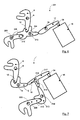
- Fig. 2
- eine schematische Ansicht der in der Vorrichtung wirksamen Hebel in Haltestellung gemäß einem ersten Ausführungsbeispiel,
- Fig. 3
- eine Detaildarstellung eines Verriegelungsglieds mit eingezeichneter Kraft durch die Federbeaufschlagung der Baueinheit und resultierendem Drehmoment im Auslösesinn,
- Fig. 4
- eine ähnliche Darstellung wie Fig. 3 mit einem zusätzlich eingezeichneten Zwischenhebel und dessen Nase zum Angreifen des Verriegelungsglieds beim Reversieren,
- Fig. 5
- eine ähnliche Ansicht wie Fig. 2 eines zweiten Ausführungsbeispiels mit einem Verriegelungsglied, das die gleichzeitige Entriegelung zweier Halterungen ermöglicht,
- Fig. 6
- eine ähnliche Ansicht wie Fig. 5 eines weiteren Ausführungsbeispiels mit zwei Verriegelungsgliedern, die an nur einem Zwischenhebel abgestützt sind,
- Fig. 7
- eine ähnlich Ansicht wie Fig. 6 eines weiteren Ausführungsbeispiels mit zwei Verriegelungsgliedern, die jeweils an einem Zwischenhebel abgestützt sind,
- Fig. 8
- eine ähnlich Ansicht wie Fig. 7 eines weiteren Ausführungsbeispiels mit zwei Verriegelungsgliedern,
- Fig. 9
- eine ähnlich Ansicht wie Fig. 8 eines weiteren Ausführungsbeispiels, das eine Kombination von mehreren der vorher dargestellten Lösungen bildet,
- Fig. 10
- eine Detaildarstellung eines von Federkraft im Haltesinn beaufschlagten Betätigungshebels,
- Fig. 11
- eine Darstellung des Gesamthebelsystems mit der Feder nach Fig. 10, die sich am Verriegelungshebel abstützt und diesen im Auslösesinn beaufschlagt,
- Fig. 12
- eine ähnliche Ansicht wie Fig. 11 mit einem Verriegelungshebel, der durch den Halteteil der Baueinheit kein im Auslösesinn wirksames Drehmoment erfährt,
- Fig. 13
- eine schematische Gesamtansicht einer Vorrichtung mit zwei Verriegelungsgliedern,
- Fig. 14
- eine schematische Gesamtansicht der Vorrichtung gemäß dem ersten Ausführungsbeispiel bei Einbettung in ein komplett montierbares Modul.
- 1,101,201,301,401,501
- Vorrichtung,
- 2
- Teilbereich der auszulösenden Baueinheit,
- 3
- Halteteil,
- 4
- Hebel,
- 5
- Feder,
- 6
- Kraftrichtung,
- 7,107
- Maul des Verriegelungshebels,
- 8,108,208,308,408
- Verriegelungshebel,
- 9,109,209,309,409
- Achse des Verriegelungshebels,
- 10
- Hebelarm,
- 11
- freies Ende des Verriegelungshebels,
- 12,212,312
- Maul des Zwischenhebels,
- 13,213,313
- Zwischenhebel,
- 14,214,314
- Achse des Zwischenhebels,
- 15
- freies Ende des Zwischenhebels,
- 16
- Aktor,
- 17,317
- Betätigungshebel,
- 18,318
- Kraft,
- 19,319
- Achse des Betätigungshebels,
- 20
- zweites Ende des Betätigungshebels,
- 21
- Hebelarm,
- 22
- Kraft,
- 23
- erstes Ende des Betätigungshebels,
- 24
- Stößel,
- 25
- Auslöserichtung des Stößels,
- 26
- Schwenkrichtung des Betätigungshebels bei Auslösung,
- 27
- Schwenkrichtung des Zwischenhebels bei Auslösung,
- 28
- Schwenkrichtung des Verriegelungshebels bei Auslösung,
- 29
- Fläche des Verriegelungshebels,
- 30
- Nase des Zwischenhebels,
- 31
- Feder,
- 32
- Modul.
Claims (18)
- Vorrichtung (1;101;201;301;401;501) zur Auslösung von schnell beweglichen Baueinheiten, insbesondere von Sicherheitsbauteilen, wobei die Vorrichtung (1;101;201;301;401;501) zumindest einen als Verriegelungsglied ausgebildeten Verriegelungshebel (8;108;208;308;408;) umfasst, welcher die Bewegung der Baueinheit in Haltestellung blockiert, und wobei die Vorrichtung (1;101;201;301;401;501) zumindest einen Betätigungshebel (17;317) umfasst, der in Haltestellung eine Bewegung des Verriegelungshebels (8;108;208;308;408) mittelbar oder unmittelbar blockiert und durch Kraftbeaufschlagung zum Lösen der Haltestellung beweglich ist,
dadurch gekennzeichnet, dass der Betätigungshebel (17;317) ein Schwenkhebel ist, der in Haltestellung frei von einer resultierenden Drehmomentbeaufschlagung durch den oder die Verriegelungshebel (8;108;208;308;408) oder weitere zwischen dem Verriegelungshebel (8;108;208;308;408) und dem Betätigungshebel (17;317) liegende Hebel (13;213;313) gehalten ist. - Vorrichtung nach Anspruch 1,
dadurch gekennzeichnet, dass der Verriegelungshebel (8;108;208;308;408) in Haltestellung von der auszulösenden Baueinheit im Bewegungssinn der schnell bewegten Auslösung kraftbeaufschlagt (5) ist und sich zur Blockierung dieser Bewegung mittelbar oder unmittelbar an dem Betätigungshebel (17;317) derart abstützt, dass auf diesen eine in der Ebene seiner Drehachse (19;319) orientierte Kraft (18;318) einwirkt. - Vorrichtung nach einem der Ansprüche 1 oder 2,
dadurch gekennzeichnet, dass der Verriegelungshebel (8;108;208;308;408) und der oder die weiteren Hebel (13;213;313;17;317) in Haltestellung ein Getriebe bilden, das eine große im Auslösesinn wirkende Kraft (6) der Baueinheit am Verriegelungsglied (8;108;208;308;408) in eine kleine Kraft an der zu haltenden Seite des Betätigungshebels (17;317) untersetzt. - Vorrichtung nach einem der Ansprüche 1 bis 3,
dadurch gekennzeichnet, dass der Verriegelungshebel (8;108;208;308;408) von einem Schwenkhebel gebildet ist, der sich in Haltestellung über einen schwenkbaren Zwischenhebel (13;213) an dem Betätigungshebel (17;317) abstützt. - Vorrichtung nach Anspruch 4,
dadurch gekennzeichnet, dass der Verriegelungshebel (8;108;208;308;408) zumindest ein nahe (Hebelarm 10) seiner Schwenkachse (9;109;209;309;409) gelegenes Aufnahmemaul (7;107) für einen Achsstummel, Zapfen oder sonstiges Halteteil (3) der auszulösenden Baueinheit und entfernter zu seiner Schwenkachse (9;109;209;309;409) ein lang erstrecktes freies Ende (11) aufweist. - Vorrichtung nach einem der Ansprüche 4 oder 5,
dadurch gekennzeichnet, dass der Zwischenhebel (13;213;313) ein nahe seiner Schwenkachse (14;214;314) gelegenes Aufnahmemaul (12;212;312) für das freie Ende (11) des Verriegelungshebels (8;108;208;308) und entfernter zu seiner Schwenkachse (14;214;314;) ein lang erstrecktes freies Ende (15) aufweist. - Vorrichtung nach einem der Ansprüche 1 bis 6,
dadurch gekennzeichnet, dass der Betätigungshebel (17;317) zumindest als einarmiger Hebel, vorzugsweise als Hebel mit einem ersten (23) und einem zweiten (20) Ende ausgebildet ist, wobei das erste Ende (23) zur Abstützung des freien Endes des Zwischenhebels (13) und eines Aktors (16) dient der bei Verwendung eines doppelarmigen Hebels jenseits seiner Schwenkachse (19;319) am zweiten Ende (20) abstützbar ist. - Vorrichtung nach einem der Ansprüche 1 bis 7,
dadurch gekennzeichnet, dass diese durch elektromagnetische Beaufschlagung des Aktors (16) aus der Halte- in eine Auslösestellung überführbar ist, in der die Hebel (8;108;208;308;408;13;213;313;17;317) ihren Kontakt zueinander verlieren und der Verriegelungshebel (8;108;208;308;408) die schnell bewegliche Baueinheit freigibt. - Vorrichtung nach einem der Ansprüche 1 bis 8,
dadurch gekennzeichnet, dass diese durch mechanische Beaufschlagung aus der Auslöse- in die Haltestellung rückführbar ist. - Vorrichtung nach einem der Ansprüche 1 bis 9,
dadurch gekennzeichnet, dass zumindest der Verriegelungshebel (8;108;208;308;408) im Auslösesinn vorgespannt ist. - Vorrichtung nach Anspruch 10,
dadurch gekennzeichnet, dass die der Vorspannung dienende Feder (31) alleinig die Auslösekraft für den Verriegelungshebel (8;108;208;308;408) aufbringt. - Vorrichtung nach einem der Ansprüche 1 bis 11,
dadurch gekennzeichnet, dass der Betätigungshebel (17;317) im Haltesinn vorgespannt ist. - Vorrichtung nach Anspruch 12,
dadurch gekennzeichnet, dass die der Vorspannung dienende Feder (31) die in dem den Betätigungshebel (17;317) antreibenden Aktor (16) üblicherweise vorgesehene Rückstellfeder ersetzt. - Vorrichtung (1;101;201;301;401;501) zur Auslösung von schnell beweglichen Baueinheiten, insbesondere von Sicherheitsbauteilen, wobei die Vorrichtung (1;101;201;301;401;501) zumindest einen als Verriegelungsglied ausgebildeten Verriegelungshebel (8;108;208;308;408) umfasst, welcher die Bewegung der Baueinheit in Haltestellung blockiert, und wobei die Vorrichtung (1;101;201;301;401;501) zumindest einen Betätigungshebel (17;317) umfasst, der in Haltestellung eine Bewegung des Verriegelungshebels (8;108;208;308;408) mittelbar oder unmittelbar blockiert und durch Kraftbeaufschlagung zum Lösen der Haftestellung beweglich ist, insbesondere nach einem der Ansprüche 1 bis 13,
dadurch gekennzeichnet, dass die Vorrichtung zur Auslösung eines Karosseriehaubenteils eines Kraftfahrzeugs im Crashfall dient. - Vorrichtung (1;101;201;301;401;501) zur Auslösung von schnell beweglichen Baueinheiten, insbesondere von Sicherheitsbauteilen, wobei die Vorrichtung (1;101;201;301;401;501) zumindest einen als Verriegelungsglied ausgebildeten Verriegelungshebel (8;108;208;308;408;) umfasst, welcher die Bewegung der Baueinheit in Haltestellung blockiert, und wobei die Vorrichtung (1;101;201;301;401;501) zumindest einen Betätigungshebel (17;317) umfasst, der in Haltestellung eine Bewegung des Verriegelungshebels (8;108;208;308;408) mittelbar oder unmittelbar blockiert und durch Kraftbeaufschlagung zum Lösen der Haltestellung beweglich ist, insbesondere nach einem der Ansprüche 1 bis 13,
dadurch gekennzeichnet, dass diese zur Auslösung eines Überrollbügels, einer Kopfstütze, einer Stoßstange, eines Gurtstraffers oder einer Sitzverstellung eines Kraftfahrzeugs im Crashfall dient. - Vorrichtung (1;101;201;301;401;501) zur Auslösung von schnell beweglichen Baueinheiten, insbesondere von Sicherheitsbauteilen, wobei die Vorrichtung (1;101;201;301;401;501 ) zumindest einen als Verriegelungsglied ausgebildeten Verriegelungshebel (8;108;208;308;408;) umfasst, welcher die Bewegung der Baueinheit in Haltestellung blockiert, und wobei die Vorrichtung (1;101;201;301;401;501) zumindest einen Betätigungshebel (17;317) umfasst, der in Haltestellung eine Bewegung des Verriegelungshebels (8;108;208;308;408) mittelbar oder unmittelbar blockiert und durch Kraftbeaufschlagung zum Lösen der Haltestellung beweglich ist, insbesondere nach einem der Ansprüche 1 bis 15,
dadurch gekennzeichnet, dass die Vorrichtung (1;101;201;301;401;501) insgesamt zusammen mit zumindest einer Feder (5) in einem Modul (32) gehalten und als Modul (32) der schnell beweglichen Baueinheit wirkungsmäßig zuortenbar ist. - Vorrichtung nach Anspruch 16,
dadurch gekennzeichnet, dass die Feder (5) vorspannbar ist. - Vorrichtung nach Anspruch 16 oder 17,
dadurch gekennzeichnet, dass der Hebel (4) der auszulösenden Baueinheit von dem Modul (32) umfasst ist.
Priority Applications (4)
| Application Number | Priority Date | Filing Date | Title |
|---|---|---|---|
| DE50305681T DE50305681D1 (de) | 2003-06-16 | 2003-06-16 | Vorrichtung zur Auslösung eines schnell beweglichen Bauteiles |
| AT03013633T ATE345243T1 (de) | 2003-06-16 | 2003-06-16 | Vorrichtung zur auslösung eines schnell beweglichen bauteiles |
| ES03013633T ES2276998T3 (es) | 2003-06-16 | 2003-06-16 | Dispositivo para accionar una pieza constructiva que se mueve con rapiudez. |
| EP03013633A EP1488965B1 (de) | 2003-06-16 | 2003-06-16 | Vorrichtung zur Auslösung eines schnell beweglichen Bauteiles |
Applications Claiming Priority (1)
| Application Number | Priority Date | Filing Date | Title |
|---|---|---|---|
| EP03013633A EP1488965B1 (de) | 2003-06-16 | 2003-06-16 | Vorrichtung zur Auslösung eines schnell beweglichen Bauteiles |
Publications (2)
| Publication Number | Publication Date |
|---|---|
| EP1488965A1 true EP1488965A1 (de) | 2004-12-22 |
| EP1488965B1 EP1488965B1 (de) | 2006-11-15 |
Family
ID=33395806
Family Applications (1)
| Application Number | Title | Priority Date | Filing Date |
|---|---|---|---|
| EP03013633A Expired - Lifetime EP1488965B1 (de) | 2003-06-16 | 2003-06-16 | Vorrichtung zur Auslösung eines schnell beweglichen Bauteiles |
Country Status (4)
| Country | Link |
|---|---|
| EP (1) | EP1488965B1 (de) |
| AT (1) | ATE345243T1 (de) |
| DE (1) | DE50305681D1 (de) |
| ES (1) | ES2276998T3 (de) |
Cited By (4)
| Publication number | Priority date | Publication date | Assignee | Title |
|---|---|---|---|---|
| EP1522470A1 (de) * | 2003-10-07 | 2005-04-13 | ISE Innomotive Systems Europe GmbH | Überrollschutzsystem für Kraftfahrzeuge, das einen ausfahrbaren Überrollkörper mit kombinierter Kopfstütze aufweist |
| DE102004062105A1 (de) * | 2004-12-23 | 2006-07-13 | Ise Innomotive Systems Europe Gmbh | Vorrichtung zum Schutz von Personen bei einem Frontalaufprall auf ein Kraftfahrzeug durch aktives Aufstellen dessen Fronthaube |
| WO2012010248A1 (de) * | 2010-07-21 | 2012-01-26 | Hydac Electronic Gmbh | Betätigungsvorrichtung für sicherheitstechnisch relevante bauteile |
| CN107448064A (zh) * | 2016-05-30 | 2017-12-08 | 成都飞机工业(集团)有限责任公司 | 一种电磁式解锁装置 |
Citations (4)
| Publication number | Priority date | Publication date | Assignee | Title |
|---|---|---|---|---|
| EP0916552A1 (de) * | 1997-11-15 | 1999-05-19 | ISE Innomotive Systems Europe GmbH | Ausfahrbarer Überrollbügel für Kraftfahrzeuge |
| DE19821594A1 (de) * | 1998-05-14 | 1999-11-18 | Thomas Magnete Gmbh | Aktor für Überrollschutzsystem |
| DE19830407A1 (de) * | 1998-07-08 | 2000-01-20 | Thomas Magnete Gmbh | Ver- und Entriegelungseinheit für ein Überrollschutzsystem |
| DE10034523A1 (de) * | 2000-07-15 | 2002-01-24 | Volkswagen Ag | Hubsystem |
-
2003
- 2003-06-16 ES ES03013633T patent/ES2276998T3/es not_active Expired - Lifetime
- 2003-06-16 DE DE50305681T patent/DE50305681D1/de not_active Expired - Lifetime
- 2003-06-16 AT AT03013633T patent/ATE345243T1/de not_active IP Right Cessation
- 2003-06-16 EP EP03013633A patent/EP1488965B1/de not_active Expired - Lifetime
Patent Citations (4)
| Publication number | Priority date | Publication date | Assignee | Title |
|---|---|---|---|---|
| EP0916552A1 (de) * | 1997-11-15 | 1999-05-19 | ISE Innomotive Systems Europe GmbH | Ausfahrbarer Überrollbügel für Kraftfahrzeuge |
| DE19821594A1 (de) * | 1998-05-14 | 1999-11-18 | Thomas Magnete Gmbh | Aktor für Überrollschutzsystem |
| DE19830407A1 (de) * | 1998-07-08 | 2000-01-20 | Thomas Magnete Gmbh | Ver- und Entriegelungseinheit für ein Überrollschutzsystem |
| DE10034523A1 (de) * | 2000-07-15 | 2002-01-24 | Volkswagen Ag | Hubsystem |
Cited By (6)
| Publication number | Priority date | Publication date | Assignee | Title |
|---|---|---|---|---|
| EP1522470A1 (de) * | 2003-10-07 | 2005-04-13 | ISE Innomotive Systems Europe GmbH | Überrollschutzsystem für Kraftfahrzeuge, das einen ausfahrbaren Überrollkörper mit kombinierter Kopfstütze aufweist |
| DE102004062105A1 (de) * | 2004-12-23 | 2006-07-13 | Ise Innomotive Systems Europe Gmbh | Vorrichtung zum Schutz von Personen bei einem Frontalaufprall auf ein Kraftfahrzeug durch aktives Aufstellen dessen Fronthaube |
| DE102004062105B4 (de) * | 2004-12-23 | 2009-08-20 | Ise Automotive Gmbh | Vorrichtung zum Schutz von Personen bei einem Frontalaufprall auf ein Kraftfahrzeug durch aktives Aufstellen dessen Fronthaube |
| WO2012010248A1 (de) * | 2010-07-21 | 2012-01-26 | Hydac Electronic Gmbh | Betätigungsvorrichtung für sicherheitstechnisch relevante bauteile |
| CN107448064A (zh) * | 2016-05-30 | 2017-12-08 | 成都飞机工业(集团)有限责任公司 | 一种电磁式解锁装置 |
| CN107448064B (zh) * | 2016-05-30 | 2024-01-12 | 成都飞机工业(集团)有限责任公司 | 一种电磁式解锁装置 |
Also Published As
| Publication number | Publication date |
|---|---|
| EP1488965B1 (de) | 2006-11-15 |
| ES2276998T3 (es) | 2007-07-01 |
| DE50305681D1 (de) | 2006-12-28 |
| ATE345243T1 (de) | 2006-12-15 |
Similar Documents
| Publication | Publication Date | Title |
|---|---|---|
| DE10034523B4 (de) | Hubsystem | |
| DE10314180B4 (de) | Reversierbarer Fußgängerschutz-Aktuator | |
| DE112010004255T5 (de) | Schalterbetätigungsmechanismus | |
| DE102009040413A1 (de) | Fahrzeug-Sicherheitseinrichtung mit einem unteren und oberen Scharnieroberteil | |
| DE10313800A1 (de) | Kopfstützenanordnung für einen Kraftfahrzeugsitz | |
| DE19706657A1 (de) | Schloss für eine Tür eines Fahrzeuges | |
| EP0235548A1 (de) | Wege- oder Durchfahrtsperre für Fahrzeuge, insbesondere zum Sperren von Ein- und Ausfahrten oder Engestellen | |
| DE102015225907A1 (de) | Lenksäule für ein Kraftfahrzeug | |
| DE102007057051A1 (de) | Deformationsvorrichtung und Fahrzeug mit der Deformationsvorrichtung | |
| EP1541425B1 (de) | Haltevorrichtung für eine Fahrzeugsicherheitsvorrichtung | |
| DE60302244T2 (de) | Pedalsicherheitssystem | |
| DE19531599A1 (de) | Kupplung für ein in eine Wirkstellung verlagerbares Sicherheitsteil eines Fahrzeugs, insbesondere für einen Überrollbügel | |
| EP1488965A1 (de) | Vorrichtung zur Auslösung eines schnell beweglichen Bauteiles | |
| EP3243980B1 (de) | Verriegelungssystem | |
| EP1951545B1 (de) | Entriegelungsvorrichtung für ein steuerteil | |
| DE102012020696A1 (de) | Vorrichtung zur mechanischen Verhinderung eines Öffnens einer Kraftfahrzeugtür bei einem Seitenaufprall und Kraftfahrzeugtür | |
| DE102004023729B4 (de) | Vorrichtung zum Aufstellen einer Fahrzeug-Tür | |
| EP0568858B1 (de) | Durch Steuerdruck verriegelbare Kolbenbetätigung, insbesondere für den Transport eines Überrollbügels bei Kraftfahrzeugen | |
| DE202004007727U1 (de) | Vorrichtung zum Aufstellen einer Fahrzeug-Tür | |
| DE102015008357B4 (de) | Schließvorrichtung für eine Fahrzeugtür, Fahrzeugtür mit einer solchen Schließvorrichtung und Fahrzeug mit zumindest einer solchen Fahrzeugtür | |
| DE10044929C1 (de) | Überrollschutzsystem | |
| DE202005005689U1 (de) | Vorrichtung zur Festlegung eines ersten Fahrzeugteiles an einem zweiten Fahrzeugteil | |
| DE102007006768A1 (de) | Überrollschutzsystem für Kraftfahrzeuge mit einem sensorgesteuert aktiv aufstellbaren Überrollkörper | |
| DE102023200554A1 (de) | Parksperrenvorrichtung, insbesondere Parksperrenvorrichtung eines Automatgetriebes | |
| DE102023000508A1 (de) | Schloss für ein Kraftfahrzeug, insbesondere Hauben- oder Klappenschloss |
Legal Events
| Date | Code | Title | Description |
|---|---|---|---|
| PUAI | Public reference made under article 153(3) epc to a published international application that has entered the european phase |
Free format text: ORIGINAL CODE: 0009012 |
|
| AK | Designated contracting states |
Kind code of ref document: A1 Designated state(s): AT BE BG CH CY CZ DE DK EE ES FI FR GB GR HU IE IT LI LU MC NL PT RO SE SI SK TR |
|
| AX | Request for extension of the european patent |
Extension state: AL LT LV MK |
|
| 17P | Request for examination filed |
Effective date: 20050607 |
|
| AKX | Designation fees paid |
Designated state(s): AT BE BG CH CY CZ DE DK EE ES FI FR GB GR HU IE IT LI LU MC NL PT RO SE SI SK TR |
|
| GRAP | Despatch of communication of intention to grant a patent |
Free format text: ORIGINAL CODE: EPIDOSNIGR1 |
|
| GRAS | Grant fee paid |
Free format text: ORIGINAL CODE: EPIDOSNIGR3 |
|
| GRAA | (expected) grant |
Free format text: ORIGINAL CODE: 0009210 |
|
| AK | Designated contracting states |
Kind code of ref document: B1 Designated state(s): AT BE BG CH CY CZ DE DK EE ES FI FR GB GR HU IE IT LI LU MC NL PT RO SE SI SK TR |
|
| PG25 | Lapsed in a contracting state [announced via postgrant information from national office to epo] |
Ref country code: SK Free format text: LAPSE BECAUSE OF FAILURE TO SUBMIT A TRANSLATION OF THE DESCRIPTION OR TO PAY THE FEE WITHIN THE PRESCRIBED TIME-LIMIT Effective date: 20061115 Ref country code: RO Free format text: LAPSE BECAUSE OF FAILURE TO SUBMIT A TRANSLATION OF THE DESCRIPTION OR TO PAY THE FEE WITHIN THE PRESCRIBED TIME-LIMIT Effective date: 20061115 Ref country code: FI Free format text: LAPSE BECAUSE OF FAILURE TO SUBMIT A TRANSLATION OF THE DESCRIPTION OR TO PAY THE FEE WITHIN THE PRESCRIBED TIME-LIMIT Effective date: 20061115 Ref country code: SI Free format text: LAPSE BECAUSE OF FAILURE TO SUBMIT A TRANSLATION OF THE DESCRIPTION OR TO PAY THE FEE WITHIN THE PRESCRIBED TIME-LIMIT Effective date: 20061115 Ref country code: NL Free format text: LAPSE BECAUSE OF FAILURE TO SUBMIT A TRANSLATION OF THE DESCRIPTION OR TO PAY THE FEE WITHIN THE PRESCRIBED TIME-LIMIT Effective date: 20061115 Ref country code: IE Free format text: LAPSE BECAUSE OF FAILURE TO SUBMIT A TRANSLATION OF THE DESCRIPTION OR TO PAY THE FEE WITHIN THE PRESCRIBED TIME-LIMIT Effective date: 20061115 |
|
| REG | Reference to a national code |
Ref country code: GB Ref legal event code: FG4D Free format text: NOT ENGLISH |
|
| REG | Reference to a national code |
Ref country code: CH Ref legal event code: EP |
|
| REF | Corresponds to: |
Ref document number: 50305681 Country of ref document: DE Date of ref document: 20061228 Kind code of ref document: P |
|
| REG | Reference to a national code |
Ref country code: IE Ref legal event code: FG4D Free format text: LANGUAGE OF EP DOCUMENT: GERMAN |
|
| REG | Reference to a national code |
Ref country code: SE Ref legal event code: TRGR |
|
| PG25 | Lapsed in a contracting state [announced via postgrant information from national office to epo] |
Ref country code: BG Free format text: LAPSE BECAUSE OF FAILURE TO SUBMIT A TRANSLATION OF THE DESCRIPTION OR TO PAY THE FEE WITHIN THE PRESCRIBED TIME-LIMIT Effective date: 20070215 Ref country code: DK Free format text: LAPSE BECAUSE OF FAILURE TO SUBMIT A TRANSLATION OF THE DESCRIPTION OR TO PAY THE FEE WITHIN THE PRESCRIBED TIME-LIMIT Effective date: 20070215 |
|
| GBT | Gb: translation of ep patent filed (gb section 77(6)(a)/1977) |
Effective date: 20070219 |
|
| PG25 | Lapsed in a contracting state [announced via postgrant information from national office to epo] |
Ref country code: PT Free format text: LAPSE BECAUSE OF FAILURE TO SUBMIT A TRANSLATION OF THE DESCRIPTION OR TO PAY THE FEE WITHIN THE PRESCRIBED TIME-LIMIT Effective date: 20070416 |
|
| NLV1 | Nl: lapsed or annulled due to failure to fulfill the requirements of art. 29p and 29m of the patents act | ||
| ET | Fr: translation filed | ||
| REG | Reference to a national code |
Ref country code: IE Ref legal event code: FD4D |
|
| REG | Reference to a national code |
Ref country code: ES Ref legal event code: FG2A Ref document number: 2276998 Country of ref document: ES Kind code of ref document: T3 |
|
| PLBE | No opposition filed within time limit |
Free format text: ORIGINAL CODE: 0009261 |
|
| STAA | Information on the status of an ep patent application or granted ep patent |
Free format text: STATUS: NO OPPOSITION FILED WITHIN TIME LIMIT |
|
| 26N | No opposition filed |
Effective date: 20070817 |
|
| PG25 | Lapsed in a contracting state [announced via postgrant information from national office to epo] |
Ref country code: MC Free format text: LAPSE BECAUSE OF NON-PAYMENT OF DUE FEES Effective date: 20070630 |
|
| REG | Reference to a national code |
Ref country code: CH Ref legal event code: PL |
|
| PG25 | Lapsed in a contracting state [announced via postgrant information from national office to epo] |
Ref country code: GR Free format text: LAPSE BECAUSE OF FAILURE TO SUBMIT A TRANSLATION OF THE DESCRIPTION OR TO PAY THE FEE WITHIN THE PRESCRIBED TIME-LIMIT Effective date: 20070216 Ref country code: LI Free format text: LAPSE BECAUSE OF NON-PAYMENT OF DUE FEES Effective date: 20070630 Ref country code: CH Free format text: LAPSE BECAUSE OF NON-PAYMENT OF DUE FEES Effective date: 20070630 |
|
| PG25 | Lapsed in a contracting state [announced via postgrant information from national office to epo] |
Ref country code: AT Free format text: LAPSE BECAUSE OF NON-PAYMENT OF DUE FEES Effective date: 20070616 |
|
| PG25 | Lapsed in a contracting state [announced via postgrant information from national office to epo] |
Ref country code: EE Free format text: LAPSE BECAUSE OF FAILURE TO SUBMIT A TRANSLATION OF THE DESCRIPTION OR TO PAY THE FEE WITHIN THE PRESCRIBED TIME-LIMIT Effective date: 20061115 |
|
| PG25 | Lapsed in a contracting state [announced via postgrant information from national office to epo] |
Ref country code: CY Free format text: LAPSE BECAUSE OF FAILURE TO SUBMIT A TRANSLATION OF THE DESCRIPTION OR TO PAY THE FEE WITHIN THE PRESCRIBED TIME-LIMIT Effective date: 20061115 Ref country code: LU Free format text: LAPSE BECAUSE OF NON-PAYMENT OF DUE FEES Effective date: 20070616 |
|
| PG25 | Lapsed in a contracting state [announced via postgrant information from national office to epo] |
Ref country code: TR Free format text: LAPSE BECAUSE OF FAILURE TO SUBMIT A TRANSLATION OF THE DESCRIPTION OR TO PAY THE FEE WITHIN THE PRESCRIBED TIME-LIMIT Effective date: 20061115 Ref country code: HU Free format text: LAPSE BECAUSE OF FAILURE TO SUBMIT A TRANSLATION OF THE DESCRIPTION OR TO PAY THE FEE WITHIN THE PRESCRIBED TIME-LIMIT Effective date: 20070516 |
|
| PGFP | Annual fee paid to national office [announced via postgrant information from national office to epo] |
Ref country code: CZ Payment date: 20120607 Year of fee payment: 10 |
|
| PGFP | Annual fee paid to national office [announced via postgrant information from national office to epo] |
Ref country code: GB Payment date: 20120621 Year of fee payment: 10 Ref country code: FR Payment date: 20120705 Year of fee payment: 10 Ref country code: SE Payment date: 20120625 Year of fee payment: 10 |
|
| PGFP | Annual fee paid to national office [announced via postgrant information from national office to epo] |
Ref country code: IT Payment date: 20120623 Year of fee payment: 10 |
|
| PGFP | Annual fee paid to national office [announced via postgrant information from national office to epo] |
Ref country code: BE Payment date: 20120622 Year of fee payment: 10 |
|
| PGFP | Annual fee paid to national office [announced via postgrant information from national office to epo] |
Ref country code: ES Payment date: 20120628 Year of fee payment: 10 |
|
| BERE | Be: lapsed |
Owner name: THOMAS MAGNETE G.M.B.H. Effective date: 20130630 |
|
| PG25 | Lapsed in a contracting state [announced via postgrant information from national office to epo] |
Ref country code: SE Free format text: LAPSE BECAUSE OF NON-PAYMENT OF DUE FEES Effective date: 20130617 Ref country code: CZ Free format text: LAPSE BECAUSE OF NON-PAYMENT OF DUE FEES Effective date: 20130616 |
|
| REG | Reference to a national code |
Ref country code: SE Ref legal event code: EUG |
|
| GBPC | Gb: european patent ceased through non-payment of renewal fee |
Effective date: 20130616 |
|
| REG | Reference to a national code |
Ref country code: FR Ref legal event code: ST Effective date: 20140228 |
|
| PG25 | Lapsed in a contracting state [announced via postgrant information from national office to epo] |
Ref country code: BE Free format text: LAPSE BECAUSE OF NON-PAYMENT OF DUE FEES Effective date: 20130630 |
|
| PG25 | Lapsed in a contracting state [announced via postgrant information from national office to epo] |
Ref country code: GB Free format text: LAPSE BECAUSE OF NON-PAYMENT OF DUE FEES Effective date: 20130616 |
|
| PG25 | Lapsed in a contracting state [announced via postgrant information from national office to epo] |
Ref country code: IT Free format text: LAPSE BECAUSE OF NON-PAYMENT OF DUE FEES Effective date: 20130616 Ref country code: FR Free format text: LAPSE BECAUSE OF NON-PAYMENT OF DUE FEES Effective date: 20130701 |
|
| REG | Reference to a national code |
Ref country code: ES Ref legal event code: FD2A Effective date: 20140707 |
|
| PG25 | Lapsed in a contracting state [announced via postgrant information from national office to epo] |
Ref country code: ES Free format text: LAPSE BECAUSE OF NON-PAYMENT OF DUE FEES Effective date: 20130617 |
|
| PGFP | Annual fee paid to national office [announced via postgrant information from national office to epo] |
Ref country code: DE Payment date: 20180630 Year of fee payment: 16 |
|
| REG | Reference to a national code |
Ref country code: DE Ref legal event code: R119 Ref document number: 50305681 Country of ref document: DE |
|
| PG25 | Lapsed in a contracting state [announced via postgrant information from national office to epo] |
Ref country code: DE Free format text: LAPSE BECAUSE OF NON-PAYMENT OF DUE FEES Effective date: 20200101 |