EP1489234A1 - Petite pelle mecanique a balancier - Google Patents
Petite pelle mecanique a balancier Download PDFInfo
- Publication number
- EP1489234A1 EP1489234A1 EP03744998A EP03744998A EP1489234A1 EP 1489234 A1 EP1489234 A1 EP 1489234A1 EP 03744998 A EP03744998 A EP 03744998A EP 03744998 A EP03744998 A EP 03744998A EP 1489234 A1 EP1489234 A1 EP 1489234A1
- Authority
- EP
- European Patent Office
- Prior art keywords
- disposed
- fuel tank
- swing type
- rotating frame
- small swing
- Prior art date
- Legal status (The legal status is an assumption and is not a legal conclusion. Google has not performed a legal analysis and makes no representation as to the accuracy of the status listed.)
- Granted
Links
- 239000002828 fuel tank Substances 0.000 claims abstract description 140
- 239000010720 hydraulic oil Substances 0.000 claims abstract description 59
- 239000003921 oil Substances 0.000 claims description 33
- 238000001816 cooling Methods 0.000 claims description 18
- 238000012423 maintenance Methods 0.000 claims description 17
- 230000002093 peripheral effect Effects 0.000 claims description 12
- 239000000945 filler Substances 0.000 claims description 9
- -1 swivel joint Substances 0.000 claims description 2
- 239000000446 fuel Substances 0.000 description 14
- 239000012535 impurity Substances 0.000 description 9
- 238000010276 construction Methods 0.000 description 5
- 239000004033 plastic Substances 0.000 description 5
- 229920003023 plastic Polymers 0.000 description 5
- 239000013049 sediment Substances 0.000 description 5
- 229910000831 Steel Inorganic materials 0.000 description 4
- 239000000463 material Substances 0.000 description 4
- 239000010959 steel Substances 0.000 description 4
- 238000009825 accumulation Methods 0.000 description 2
- 238000004140 cleaning Methods 0.000 description 2
- 239000000428 dust Substances 0.000 description 2
- 230000020169 heat generation Effects 0.000 description 2
- 238000000034 method Methods 0.000 description 2
- 230000015572 biosynthetic process Effects 0.000 description 1
- 238000011109 contamination Methods 0.000 description 1
- 230000000881 depressing effect Effects 0.000 description 1
- 238000001746 injection moulding Methods 0.000 description 1
- 239000003350 kerosene Substances 0.000 description 1
- 238000003754 machining Methods 0.000 description 1
- 239000004576 sand Substances 0.000 description 1
- 230000002195 synergetic effect Effects 0.000 description 1
Images


Classifications
-
- B—PERFORMING OPERATIONS; TRANSPORTING
- B60—VEHICLES IN GENERAL
- B60K—ARRANGEMENT OR MOUNTING OF PROPULSION UNITS OR OF TRANSMISSIONS IN VEHICLES; ARRANGEMENT OR MOUNTING OF PLURAL DIVERSE PRIME-MOVERS IN VEHICLES; AUXILIARY DRIVES FOR VEHICLES; INSTRUMENTATION OR DASHBOARDS FOR VEHICLES; ARRANGEMENTS IN CONNECTION WITH COOLING, AIR INTAKE, GAS EXHAUST OR FUEL SUPPLY OF PROPULSION UNITS IN VEHICLES
- B60K15/00—Arrangement in connection with fuel supply of combustion engines or other fuel consuming energy converters, e.g. fuel cells; Mounting or construction of fuel tanks
- B60K15/03—Fuel tanks
- B60K15/073—Tank construction specially adapted to the vehicle
-
- E—FIXED CONSTRUCTIONS
- E02—HYDRAULIC ENGINEERING; FOUNDATIONS; SOIL SHIFTING
- E02F—DREDGING; SOIL-SHIFTING
- E02F3/00—Dredgers; Soil-shifting machines
- E02F3/04—Dredgers; Soil-shifting machines mechanically-driven
- E02F3/28—Dredgers; Soil-shifting machines mechanically-driven with digging tools mounted on a dipper- or bucket-arm, i.e. there is either one arm or a pair of arms, e.g. dippers, buckets
- E02F3/30—Dredgers; Soil-shifting machines mechanically-driven with digging tools mounted on a dipper- or bucket-arm, i.e. there is either one arm or a pair of arms, e.g. dippers, buckets with a dipper-arm pivoted on a cantilever beam, i.e. boom
- E02F3/32—Dredgers; Soil-shifting machines mechanically-driven with digging tools mounted on a dipper- or bucket-arm, i.e. there is either one arm or a pair of arms, e.g. dippers, buckets with a dipper-arm pivoted on a cantilever beam, i.e. boom working downwardly and towards the machine, e.g. with backhoes
- E02F3/325—Backhoes of the miniature type
-
- E—FIXED CONSTRUCTIONS
- E02—HYDRAULIC ENGINEERING; FOUNDATIONS; SOIL SHIFTING
- E02F—DREDGING; SOIL-SHIFTING
- E02F9/00—Component parts of dredgers or soil-shifting machines, not restricted to one of the kinds covered by groups E02F3/00 - E02F7/00
- E02F9/08—Superstructures; Supports for superstructures
- E02F9/0858—Arrangement of component parts installed on superstructures not otherwise provided for, e.g. electric components, fenders, air-conditioning units
- E02F9/0883—Tanks, e.g. oil tank, urea tank, fuel tank
-
- E—FIXED CONSTRUCTIONS
- E02—HYDRAULIC ENGINEERING; FOUNDATIONS; SOIL SHIFTING
- E02F—DREDGING; SOIL-SHIFTING
- E02F9/00—Component parts of dredgers or soil-shifting machines, not restricted to one of the kinds covered by groups E02F3/00 - E02F7/00
- E02F9/16—Cabins, platforms, or the like, for drivers
- E02F9/163—Structures to protect drivers, e.g. cabins, doors for cabins; Falling object protection structure [FOPS]; Roll over protection structure [ROPS]
Definitions
- the present invention relates to a small swing type excavator, wherein an upper rotating body rotates in such a condition that the rear end thereof hardly projects outside the width of a lower traveling body.
- small swing type or short-radius excavator wherein a rear end rotating radius of an upper rotating body is set to about 1/2 of the width of a lower traveling body, can rotate 360 degrees in such a condition that the rear end of the upper rotating body hardly projects outside the width of the lower traveling body, which is therefore suitable for work in narrow places such as urban work or subway work.
- an air conditioner may be provided in a seat stand as shown in the art disclosed in Japanese Patent Laid-Open Publication No. 2001-295319, while in the case of short-radius excavators, there may exist part of an engine under a seat stand, resulting in a difficulty in ensuring enough space in the seat stand.
- the present invention has been made in consideration of the above-described circumstances and a first object thereof is to provide a short-radius excavator, wherein the volume of a fuel tank is increased as much as possible with ensuring of an arrangement space for air conditioner to allow effective use of the space in a rotating frame.
- the present invention has been made in consideration of the above-described circumstances and a second object thereof is to provide a short-radius excavator, wherein problems that occur when arranging an engine in a slanted manner are overcome to allow effective use of the space in a rotating frame.
- a working device Composed of, for example, a boom, an arm, etc.
- the front rotating radius increases, resulting in a disadvantage in terms of degree of freedom in, for example, excavating work using the working device.
- a working device Composed of, for example, a boom, an arm, etc.
- the front rotating radius increases, resulting in a disadvantage in terms of degree of freedom in, for example, excavating work using the working device.
- in front of the upper rotating body is required a lot of space to arrange pipes from the control valve on the upper rotating body through hydraulic actuators such as a hydraulic cylinder of the working device.
- the present invention has been made in consideration of the above-described circumstances and a third object thereof is to realize an device layout that makes effective use of the space in the width direction of a rotating frame of a short-radius excavator in which a working device is pivoted movably in the lateral and longitudinal directions in a protruding manner from the front end of the upper rotating body.
- a small swing type excavator wherein an upper rotating body is mounted rotatably around a vertical shaft on a lower traveling body, rotating radius of a rear end of the upper rotating body being set to about one half of the width of the lower traveling body and devices being mounted on a rotating frame of the upper rotating body, characterized in that an operator cab is disposed on one lateral side on the rotating frame, and that an air conditioner and a fuel tank are provided, respectively, on an inner and an outer side in the width direction of the excavator in a space under a floor of the operator cab, the fuel tank comprising an extension portion extending to at least the front surface side of the air conditioner.
- being set to about one half means that the rear end of the rotating frame does not project outside the width of the lower traveling body, or that projects only up to one half of the vehicle width + 10% thereof (the same applies hereinafter).
- the operator cab is disposed on one lateral side on the rotating frame, and the air conditioner and the fuel tank are provided, respectively, on an inner and an outer side in the width direction of the excavator in the space under the floor of the operator cab, the fuel tank comprising an extension portion extending to at least the front surface side of the air conditioner, whereby providing the large-sized fuel tank utilizing the blank space, for example, in front of the air conditioner which has not been conventionally used, the volume of the fuel tank may be increased with ensuring of an arrangement space for the air conditioner. It is noted that if including no heat source, plastic fuel tanks having high-degree of freedom of machining shape have become employed frequently in recent years. Therefore, employing these kinds of plastic fuel tanks allows easy formation even in the case of complicated shapes comprising extension portions.
- the fuel tank be detachably attached to the rotating frame in such a condition that the extension portion extends along at least the front surface side of the air conditioner, and that an opening portion capable of taking the fuel tank inside and outside therethrough be provided in an outer peripheral wall of the rotating frame.
- the fuel tank when impurities accumulate at the bottom with age, the fuel tank may be detached from the rotating frame to be cleaned on the outside thereof before the engine as a motor becomes inoperative (engine down), and then the impurities accumulated at the bottom of the fuel tank can be removed to prevent engine down. Meanwhile, in the unlikely event that the engine goes down, the fuel tank may be detached from the rotating frame to be cleaned on the outside thereof, and then the impurities accumulated at the bottom of the fuel tank can also be removed to restart the operation of the engine.
- an opening portion is provided in the outer peripheral wall of the rotating frame
- sediments generated during construction work may get inside through the opening portion to accumulate around the fuel tank.
- a cover portion adapted to cover the opening portion be further provided in the outer peripheral wall of the rotating frame.
- the configuration above is suitable particularly for plastic tanks that have low impact resistance compared to steel ones.
- a small swing type excavator wherein an upper rotating body is mounted rotatably around a vertical shaft on a lower traveling body, rotating radius of a rear end of the upper rotating body being set to about one half of the width of the lower traveling body and devices being mounted on a rotating frame of the upper rotating body, characterized in that a power source is disposed in a rear section of the rotating frame in such a manner that said power source laterally stretches long and both lateral ends of said power source are longitudinally shifted each other to be inclined; a hydraulic pump is disposed on one end side closer to the rear side of both the lateral ends of the power source, while a cooling device is disposed on the other end side closer to the front side of both the lateral ends; a fuel tank is disposed in front of the hydraulic pump through a predetermined space; and a hydraulic oil tank is disposed in the predetermined space.
- the power source is disposed in the rear section of the rotating frame in such a manner that said power source laterally stretches long and both lateral ends of said power source are longitudinally shifted each other to be inclined whereby it never occurs that most of the space in the rear section of the rotating frame of the upper rotating body is occupied only by the power source. That is, although the shape of the power source is determined almost automatically to meet the function thereof, when arranging the power source in such an inclined or slanted manner, a certain space (predetermined space) can be ensured in front of one lateral side from where the power source is moved backward away.
- the hydraulic pump is disposed on one end side closer to the rear side of both the lateral ends of the power source, while the cooling device is disposed on the other end side closer to the front side;
- the fuel tank is disposed in front of the hydraulic pump through a predetermined space; and the hydraulic oil tank is disposed in the space, whereby the amount of suction pipes on the rotating frame is reduced, and combined with the slanted arrangement of the power source, it is further possible to allow for the device arrangement in the rotating frame.
- the fuel tank be disposed on one end side across a swivel joint disposed at the center of rotation, while a control valve be disposed on the other end side, the fuel tank and the control valve being in front of the power source.
- a control valve be disposed on the other end side, the fuel tank and the control valve being in front of the power source.
- an operator cab be disposed on the upper surface on one lateral side of the rotating frame, and that the fuel tank be arranged under the floor of the operator cab.
- other devices can be arranged high in the vehicle, whereby the layout is facilitated.
- the hydraulic oil tank be formed into a fan shape in such a manner that the hydraulic oil tank spreads outward from the rotating frame when viewed vertically.
- the maximum volume of the hydraulic oil tank can be obtained between the power source arranged in a slanted manner and the fuel tank (or operator cab).
- the hydraulic oil tank be formed in such a manner that at least part thereof reaches to under the hydraulic pump. In this case, the volume of the fuel tank can be further increased.
- the rotating frame comprise an opening portion for maintenance at the end on the side where the control valve and the cooling device are provided, and a cover portion adapted to cover the opening portion.
- the control valve and the cooling device can be maintained easily by opening the cover portion.
- devices can be maintained easily if necessary.
- a small swing type excavator wherein the upper rotating body is mounted rotatably around a vertical shaft on a lower traveling body, and wherein a working device is attached pivotedly at a front end of the upper rotating body, rotating radius of a rear end of the upper rotating body being set to about one half of the width of the lower traveling body and devices being mounted on a rotating frame of the upper rotating body, characterized in that a hydraulic pump, a power source and a cooling device are disposed laterally in a line as rear row devices in a rear section of the rotating frame; and in front of the rear row devices, a control valve and a hydraulic oil tank are disposed in a line on one lateral side centering on a swivel joint, while a fuel tank is disposed on the other lateral side, the control valve, the hydraulic oil tank, and the fuel tank constituting front row devices.
- the hydraulic pump, the power source and the cooling device are disposed laterally in a line as rear row devices in the rear section of the rotating frame of the upper rotating body; and in front of the rear row devices, the control valve and the hydraulic oil tank are disposed in a line on one lateral side centering on the swivel joint, while the fuel tank is disposed on the other lateral side as front row devices, whereby the space in the width direction of the rotating frame is used effectively in the small swing type excavator wherein a working device is attached pivotedly at the front end of the upper rotating body, and major devices are arranged in two lines from near the center of the rotating frame through the rear section in the longitudinal direction. Consequently, the arrangement of pipes for the major devices is facilitated, and further the maintenance performance thereof is also improved.
- swinging motors have conventionally been arranged in the front part of rotating frames.
- a swinging motor be disposed between the swivel joint and the hydraulic oil tank. In this case, further space in the longitudinal direction is ensured to facilitate the device layout.
- an air conditioner be disposed between the swivel joint and the fuel tank. In this case, an arrangement space for the air conditioner can be ensured to facilitate the layout thereof.
- the fuel tank be arranged under the floor of an operator cab disposed in the upper rotating body. In this case, an arrangement space for the fuel tank can be ensured to facilitate the layout thereof.
- the rear row devices be arranged laterally in the order of hydraulic pump, power source and cooling device, while the front row devices be arranged laterally in the order of fuel tank, swivel joint, hydraulic oil tank and control valve, the fuel tank being arranged under the floor of an operator cab disposed in the upper rotating body and the hydraulic pump being located in a rear side of the fuel tank.
- the fuel tank being arranged under the floor of an operator cab disposed in the upper rotating body and the hydraulic pump being located in a rear side of the fuel tank.
- suction pipe that communicates the hydraulic pump and the hydraulic oil tank and a delivery pipe that communicates the hydraulic pump and the control valve between the rear row devices and the front row devices almost linearly, whereby the arrangement of pipes is facilitated and pressure loss in the pipes can be reduced.
- the suction pipe has a large diameter, and therefore arranging the pipe with less number of bends has advantages in terms of ensuring the easiness of the arrangement.
- control valve is relatively small, in accordance with the present invention, disposed on the outside of the hydraulic oil tank that requires a large space, whereby the control valve can be arranged along the arc-shape of the rotating frame, improving the usability of the space.
- the fuel tank is arranged under the floor of the operator cab, which allows effective use of the arrangement space for devices on the upper rotating body.
- the hydraulic oil tank is arranged between the floor of the operator cab and the control valve, whereby it is avoided that noises such as working oil flowing sound and restricting sound from the control valve reach operators in the operator cab to reduce the comfort therein.
- major devices can be arranged effectively in a small swing type excavator with a small arrangement space for devices, providing a saving of energy at the same time and also giving advantages in terms of controlling a hydraulic circuit, and further noises that may reach operators can be limited.
- a battery be disposed on the outside of the fuel tank in the lateral direction.
- the battery which requires to be maintained appropriately, is arranged outside the fuel tank, which facilitates the maintenance of the battery as well as, for example when cleaning the fuel tank, the detachment of the fuel tank by detaching the battery.
- the arrangement above is found to be effective.
- an air conditioner be disposed over the floor of the operator cab, for example, under the operator seat, or in a cabin if provided for the operator cab.
- the space under the floor of the operator cab can be used more effectively, that is, for example, the volume of the fuel tank can be increased.
- small swing type excavators having a canopy in which the space over the floor of the operator cab is opened outward, include no air conditioner, the space under the floor of the operator cab can be used effectively even in such a case.
- the suction pipe that communicates the hydraulic pump and the control valve be guided under the floor of the operator cab, while a pilot pipe that communicates the control valve and a pilot valve disposed over the floor of the operator cab be guided over the floor of the operator cab.
- a pilot pipe that communicates the control valve and a pilot valve disposed over the floor of the operator cab be guided over the floor of the operator cab.
- an arrangement of the pipes in the space under the floor of the operator cab can be formed simply.
- a swinging motor be disposed in front or rear of the swivel joint.
- the space between the hydraulic oil tank, which is enlarged longitudinally to increase the volume thereof, and the fuel tank can be used more effectively.
- an oil filler port of the fuel tank be disposed in the rear section thereof and above the hydraulic pump. In this case, it is possible to make effective use of the blank space over the hydraulic pump that is shorter in height than the cooling device.
- an operation pattern switching valve for switching a motion pattern of an actuator according to an operation of an operation means among multiple motion patterns be disposed in front of the hydraulic oil tank.
- elements having switching portion can be arranged around the control valve in a concentrated manner, which makes it possible to perform maintenance in a lump from the same place.
- an operation lock valve for locking actuators hydraulically to be inoperative be disposed in the vicinity of the hydraulic oil tank in front or rear of the control valve. Also in this case, elements having switching portion can be arranged around the control valve in a concentrated manner, which makes it possible to perform maintenance in a lump from the same place.
- Fig. 1 shows the overall construction of a so-called small swing type or short-radius excavator among various types of small hydraulic excavators, in which the vehicle body of the short-radius excavator consists of a lower traveling body 1, an upper rotating body 2 mounted rotatably around a vertical shaft on the lower traveling body 1, an excavating attachment not shown in the figure consisting of, for example, a boom pivoted movably in the lateral direction at a support member of a working device that is provided at the front end of the upper rotating body 2 in a protruding manner, and a dozer 3 pivoted movably in the vertical direction to the lower traveling body 1, etc.
- the vehicle body of the short-radius excavator consists of a lower traveling body 1, an upper rotating body 2 mounted rotatably around a vertical shaft on the lower traveling body 1, an excavating attachment not shown in the figure consisting of, for example, a boom pivoted movably in the lateral direction at a support member of a working device that is provided
- the lower traveling body 1 consists of right and left crawler frames 4 and crawlers 5 (only one side, respectively, thereof is shown in the figure), the crawlers 5 on the both sides being driven rotationally separately by right and left traveling motors 7 to run the vehicle.
- the upper rotating body 2 comprises a rotating frame 8, the rear end rotating radius of which being set to about one half or of the width of the lower traveling body 1, and a counterweight 9, on the rotating frame 8 being mounted a cabin 83 having a substantially sealed structure to form an operator cab, an engine and devices such as a hydraulic pump driven by the engine, as will be described hereinafter.
- the cabin 83 among the above-mentioned components is formed into a box shape having a ceiling, front and rear walls, and right and left walls as peripheral walls, and has the substantially sealed structure, which is adapted to shut out outside air to protect operators against outside noise, dust, etc., wherein an air conditioner 85 is provided to ensure habitability thereof.
- Figs. 2A and 2B the left side in Fig. 2A corresponds to front side, the right side to rear side, the upper side to right side, and the lower side to left side.
- the rotating frame 8 is formed into a little flattened cylinder shape cutting off part of the front side, and a floor 84 (flat part under the operator cab) of the cabin 83 is formed substantially within the left half from the front side through the central portion (the floor 84 is represented by the dashed line in Fig. 2A).
- the rotating frame 8 is set to be shorter longitudinally, while a little longer laterally in comparison with common small hydraulic excavators.
- an engine (referred to as E/G in Fig.2) 81 as a power source mounted transversely with an output shaft thereof extending laterally in the rear section of the rotating frame 8, a hydraulic oil tank (H/T likewise as above) 82 disposed in front and right of the engine 81, the cabin 83 disposed in front and left of the engine 81, an air conditioner (A/C likewise as above) 85 disposed on an inner side in the width direction of the excavator in the space under the floor 84 of the cabin 83, and a fuel tank (F/T likewise as above) 86 disposed on the outside of the air conditioner 85.
- E/G in Fig.2 an engine
- E/G in Fig.2 a power source mounted transversely with an output shaft thereof extending laterally in the rear section of the rotating frame 8
- a hydraulic oil tank H/T likewise as above
- A/C air conditioner
- F/T fuel tank
- the numeral 801 indicates a control valve (C/V likewise as above), 802 a manipulation pattern switching valve (M/V likewise as above), 803 a swinging motor (S/M likewise as above), 804 a swivel joint (S/J likewise as above), 805 a battery (BAT likewise as above), 807 a hydraulic pump (P likewise as above), 808 a radiator (R/D likewise as above), and 809 an oil cooler (O/C likewise as above).
- the engine 81 is, for example, a diesel engine, wherein the hydraulic pump 807 is connected to one end of the output shaft, while a fan, not shown in the figure, is attached to the other end thereof to air-cool the radiator 808 and the oil cooler 809.
- the hydraulic oil tank 82 is a steel tank for storing hydraulic oil from each hydraulic device. Then, an oil filler port extends up to the outer peripheral wall of the rotating frame 8, although not shown in the figure, which allows fueling of the tank. Also, an oil discharge port closed with a cap is provided at a position where an operator can access from under the rotating frame 8, and then remove the cap to recover discharge oil when performing maintenance.
- the air conditioner 85 While part of the unit (although there are included a condenser unit and an air conditioner unit, the former is here ignored, the same applying hereinafter) protrudes inside a seat stand 87, most part of the unit is arranged under the floor 84 of the cabin 83 (the part arranged under the floor will hereinafter be referred to simply as the air conditioner 85).
- the fuel tank 86 is a tank having a complicated shape that stores fuel for the engine 81, which is made of, for example, plastics with remarkable workability.
- the fuel tank 86 is installed in the extremely narrow space of under the floor 84 of the cabin 83 together with the air conditioner 85, and thereby has a flattened shape wholly that has not conventionally been able to allow for enough volume.
- the structure of the fuel tank 86 is adapted to comprise an extension portion extending to at least the front surface side of the air conditioner 85, whereby an ever-larger volume can be ensured.
- the fuel tank 86 consists of, as shown in Fig.4, a ceiling surface 86a and a bottom surface 86b formed into an L shape, a front surface 86c, a left side surface 86d, rear surfaces 86e and 86f, and right side surfaces 86g and 86h formed into respective rectangular shapes, the left side surface 86g and the rear surface 86f being arranged along, respectively, the left side surface and the front surface of the air conditioner 85.
- Even complicated shapes such as the L shape above can be formed easily by means, for example, of injection molding if the tank is made of plastics.
- a sensor 863 to detect the amount of fuel in the fuel tank 86, and for example, a warning light in the cabin 83 is to be turned on by receiving a signal from the sensor 863 when the fuel gets low.
- the sensor 863 is formed with, for example, a float switch, which is to be taken outside in an integrated manner with the tank when taking the tank outside as will be described hereinafter. Therefore, the sensor 863 is connected to a guided wire in the rotating frame 8 through a connector not shown in the figure. Then, the connector is to be disconnected to take the tank outside.
- an oil filler port 865 closed with a cap 864 protrudes in rear and left of the ceiling surface 86a.
- the oil filler port 865 extends up to the outer wall of the rotating frame 8, which makes it possible to fuel the tank by removing the cap 864 in such a condition that the tank is installed in a predetermined position.
- a fuel suction port 866 is provided in an appropriate position of the ceiling surface 86a, the fuel suction port 866 being connected to a guided pipe that leads to a fuel feeding device for the engine 81 in the rotating frame through a joint not shown in the figure. Then, the joint is to be disconnected to take the tank outside. It is noted that it is preferable to provide the position of the fuel suction port 866 in the vicinity of the center of rotation of the excavator as close as possible to prevent air intake, even in the case of work on an inclined surface, which can be made responsive by giving a guided pipe suitable in the tank to the fuel suction port 866, unlike in the case of the sensor 863 above.
- the fuel tank 86 is detachably attached to the rotating frame using, for example, a band not shown in the figure, particularly in case of contamination of foreign materials into the tank, where the fuel tank 86 can be taken outside the rotating frame 8 by removing the band. Therefore, a holding part, etc. for taking the tank outside may be provided in an appropriate position of the fuel tank 86.
- an opening portion 861 having an area capable of taking the fuel tank 86 outside together with the sensor 863 in the take-out direction of the fuel tank 86, as well as a cover portion 862 adapted to cover the opening portion 861 while not taking the tank 86 outside.
- the cover portion 862 is made of steel, the same material as the outer wall, and is fastened with bolts around the opening portion 861 of the outer wall, while may be hinged openably to the opening portion 861 for example.
- frictional force at the bottom of the fuel tank 86 in the rotating frame 8 may be reduced to make it easy to take the tank outside, and a sliding rail, etc. may be provided along the movement route of the tank so that the tank is returned to the original position thereof accurately again.
- the fuel tank 86 is arranged along two surfaces of the front and left side surfaces of the air conditioner 85, and there is fixed to the rotating frame 8 using the band above.
- an operator When performing maintenance, an operator first opens the cover portion 862 of the rotating frame 8, and disconnect the connector of the sensor 863 of the fuel tank 86 from the guided wire in the rotating frame 8 through the opening portion 861 as well as disconnect the joint of the fuel suction port 866 from the guided pipe in the rotating frame 8, and then removes the band fixing the fuel tank 86. Then, the fuel tank 86 is pulled toward this side in the figure from a fixed position on the rotating frame 8 through the opening portion 861.
- a simple pump, etc. are connected to the joint of the fuel suction port 866 of the fuel tank 86 taken outside to drain remaining fuel completely, and then the inside of the tank is cleaned with kerosene, etc. to remove foreign materials.
- impurities accumulated at the bottom of the fuel tank 86 can be removed.
- the fuel tank 86 is returned to the original position thereof by a reverse procedure to above and is fixed using the band, and the connector of the sensor 863 of the fuel tank 86 is connected to the guided wire in the rotating frame 8 as well as the joint of the fuel suction port 866 is connected to the guided pipe in the rotating frame 8, and then the opening portion 861 is closed with the cover portion 862.
- the fuel tank 86 may be detached from the rotating frame 8 to be cleaned on the outside thereof before the engine 81 becomes inoperative (engine down), and then impurities accumulated at the bottom of the fuel tank 86 can be removed to prevent engine down. Meanwhile, in the unlikely event that the engine goes down, the fuel tank 86 may be detached from the rotating frame 8 to be cleaned on the outside thereof, and then impurities accumulated at the bottom of the fuel tank 86 can also be removed to restart the operation of the engine 81. Also, it is possible to make it unlikely by means of the cover portion 862 that sediments may get inside around the fuel tank 86 through the opening portion 861, and to protect the fuel tank 86 against unexpected direct hits by sediments, etc.
- the cabin 83 is disposed on one lateral side on the rotating frame 8 of the upper rotating body 2, and the air conditioner 85 and the fuel tank 86 are provided, respectively, on an inner and an outer side in the width direction of the excavator in the space under the floor 84 of the cabin 83, the fuel tank 86 comprising the extension portion extending to at least the front surface side of the air conditioner 85, whereby providing the large-sized fuel tank 86 utilizing the blank space in front of the air conditioner 85 which has not been conventionally used, the volume of the fuel tank 86 may be increased with ensuring of an arrangement space for the air conditioner 85. Therefore, it is possible to ensure the volume of the fuel tank 86 to increase the fueling interval, resulting in an improvement in operating efficiency.
- the fuel tank 86 although formed in an L shape when viewed vertically and arranged along the front and left side surfaces of the air conditioner 85 in the first embodiment above, may be arranged along three surfaces of both the front and rear surfaces and the left side surface in some cases (in these cases, the fuel tank is to be formed into a U shape when viewed vertically). Also, it will be appreciated that in the case the overall arrangement of the rotating frame 8 above is reversed laterally, the fuel tank may be formed in accordance with such arrangement (in this case, the fuel tank is to be arranged along the front (and rear) and left side surfaces of the air conditioner).
- Figs. 5A and 5B The device layout in a rotating frame 8 that characterizes the present second embodiment will be described in detail with reference to Figs. 5A and 5B. It is noted that the left side in Fig. 5A corresponds to front side, the right side to rear side, the upper side to right side, and the lower side to left side, and for the sake of convenience, the same numerals are assigned to components in Figs. 5A and 5B in common with those in the first embodiment above.
- the configuration of the rotating frame 8 shown in Figs. 5A and 5B is the same as that of the first embodiment.
- the floor 84 is represented by the dashed line in Fig. 5A.
- an engine (E/G) 81 as a power source is disposed in the rear section of the rotating frame 8, though in a laterally stretched long attitude, in a slanted manner where both the lateral ends are longitudinally shifted each other so that the longitudinal direction thereof is arranged at a predetermined angle with the lateral center line of the rotating frame 8. Then, on the right end side (one end side) closer to the front side of the engine 8 in the slanted manner are disposed a radiator (R/D) 808 and an oil cooler (O/C) 809 as cooling devices in this order outward, while on the left end side (the other end side) closer to the rear side than the right end side is provided a hydraulic pump (P) 807.
- R/D radiator
- O/C oil cooler
- the numeral 802 indicates an operation or a manipulation pattern switching valve (M/V), while 805 a battery (BAT).
- the reason for arranging the devices centering on the swivel joint 804 is that the fuel tank 86 and the control valve 801 can be arranged separately close to the vicinity of the outer peripheral wall where the width of the rotating frame 8 is maximized, whereby the volume of the fuel tank 86 can be ensured and the maintenance performance of the control valve 801 can be improved.
- the hydraulic oil tank 82 is formed into a fan shape in such a manner that the tank 82 spreads outward from the rotating frame 2 when viewed vertically so as to fit into the space between the hydraulic pump 807 and the fuel tank 86, which is generated by arranging the engine 81 in the slanted manner.
- the hydraulic oil tank 82 consists of, as shown in Fig. 6, a ceiling surface 82a and a bottom surface 82b formed into a fan shape, a left side surface 82d curved with a predetermined curvature along the outer wall of the rotating frame 8, a front surface 82c, a rear surface 82e, and a right side surface 82f formed into respective rectangular shapes.
- a space under the hydraulic pump 807 which may be further utilized.
- a projecting portion 821 can be provided at the left lower part of the rear surface 82e of the hydraulic oil tank 82 as shown by the two-dot chain line in Fig. 6.
- the projecting portion 821 has a height capable of getting under the hydraulic pump 807 and a geometry capable of having no contact with the body of the engine 81.
- the maximum volume of the hydraulic oil tank 82 can be obtained. It is noted that depending on the arrangement of other devices in the rotating frame 8, the whole of the hydraulic oil tank 82 may be fitted into the space under the hydraulic pump 807.
- an oil filler port extends up to the outer peripheral wall of the rotating frame 8, although not shown in the figure, which allows fueling of the tank 82. Further, an oil discharge port closed with a cap is provided at a position where workers can access from under the rotating frame 8, and then remove the cap to recover discharge oil when performing maintenance.
- An oil filler port of the fuel tank 86 extends up to the outer peripheral wall of the rotating frame 8, although not shown in the figure, which allows fueling of the tank 86. It is easy to do the layout of the fuel tank 86, due to the excellent workability thereof, even in such a narrow space as under the floor 84 of the cabin 83 where the fuel tank 86 is arranged together with the air conditioner 85. Then, other devices can be arranged high in the vehicle, whereby the layout is facilitated.
- an opening portion 811 having an area capable of maintaining the control valve 801, the radiator 808 and the oil cooler 809, etc., as well as a cover portion 812 adapted to cover the opening portion 811 while not maintaining such devices.
- the cover portion 812 is made of steel, the same material as the outer wall, and is fastened with bolts around the opening portion 811 of the outer wall, while may be hinged openably to the opening portion 811 for example. Thus, devices can be maintained easily if necessary by opening the cover portion 812.
- the engine 81 is disposed in the rear section of the rotating frame 8 in a laterally stretched long attitude and a slanted manner where both the lateral ends are longitudinally shifted, whereby it never occurs that most of the space in the rear section of the rotating frame of the upper rotating body is occupied only by the engine 81. That is, although the shape of the engine 81 is determined almost automatically to meet the function thereof, when arranging the engine 81 in such a slanted manner, a certain space can be ensured in front of one lateral side from where the power source is moved backward away.
- the hydraulic pump 807 is disposed on one end side closer to the rear side of both the lateral ends of the engine 81, while the radiator 808 and the oil cooler 809 are disposed on the other end side closer to the front side; the fuel tank 86 is disposed in front of the hydraulic pump 807 through the foregoing predetermined space; and the hydraulic oil tank 82 is disposed in this space, whereby the amount of suction pipes on the rotating frame 8 is reduced, and combined with the slanted arrangement of the engine 81, it is further possible to allow for the device arrangement in the rotating frame 8.
- the working oil tank 82 is formed into a fan shape when viewed vertically in the second embodiment above, it is possible to adopt every kind of other shapes capable of realizing large volume. Also, it will be appreciated that the overall arrangement of the rotating frame 8 above may be reversed laterally and the fuel tank may be formed in accordance with such arrangement.
- the air conditioner 85 although disposed between the swivel joint 804 and the fuel tank 86 in the second embodiment above, is not required to be installed in such a case where no cabin 83 is provided, which further allows for the device arrangement.
- the working device is attached pivotedly in the lateral and longitudinal directions in a protruding manner from the front end of the upper rotating body 2 in Fig. 1
- the invention according to the third to fifth embodiments described hereinafter is directed to short-radius excavators in which a working device is attached pivotedly the lateral and longitudinal directions in a protruding manner from the front end of the upper rotating body 2.
- the embodiments will hereinafter be described.
- Figs. 7A and 7B The device layout in a rotating frame 8 that characterizes the present third embodiment will be described in detail with reference to Figs. 7A and 7B. It is noted the left side in Fig. 7A corresponds to front side, the right side to rear side, the upper side to right side, and the lower side to left side, and for the sake of convenience, the same numerals are assigned to components in Figs. 7A and 7B in common with those in the first and second embodiments above.
- the configuration of the rotating frame 8 shown in Figs. 7A and 7B is the same as that of the first and second embodiments.
- the floor 84 is represented by the dashed line in Fig. 7A.
- a hydraulic pump (P) 807, an engine (E/G) 81, a radiator (R/D) 808, and an oil cooler (O/C) 809 are disposed in a line from the left to right side in this order as rear row devices in the rear section of the rotating frame 8; and in front of the rear row devices, a swinging motor (S/M) 803, a hydraulic oil tank (H/T) 82, and a control valve (C/V) 801 are disposed in a line in this order on the right side of a swivel joint (S/J) 804, while on the left side thereof an air conditioner (A/C) 85 and a fuel tank (F/T) 86 in a line in this order as front row devices.
- the numeral 802 indicates an operation or a manipulation pattern switching valve (M/V), while 805 a battery (BAT).
- An oil discharge port of the hydraulic oil tank 82 closed with a cap is provided at a position where an operators can access from under the rotating frame 8, and then remove the cap to recover discharge oil when performing maintenance.
- An oil filler port of the fuel tank 86 extends up to the outer peripheral wall of the rotating frame 8, although not shown in the figure, which allows fueling of the tank.
- the hydraulic pump (P) 807, the engine (E/G) 81, the radiator (R/D) 808, and the oil cooler (O/C) 809 are disposed in a line from the left to right side in this order as rear row devices in the rear section of the rotating frame 8 of the upper rotating body 2; and in front of the rear row devices, the swinging motor (S/M) 803, the hydraulic oil tank (H/T) 82, and the control valve (C/V) 801 are disposed in a line in this order on the right side of the swivel joint (S/J) 804, while on the left side thereof the air conditioner (A/C) 85 and the fuel tank (F/T) 86 in a line in this order as front row devices, whereby the space in the width direction of the rotating frame 8 is used effectively in the short-radius excavator in which a working device is attached pivotedly at the front end of the upper rotating body 2, and major devices are arranged in two lines from near the center
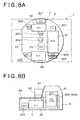
- Figs. 8A and 8B the left side in Fig. 8A corresponds to front side, the right side to rear side, the upper side to right side, and the lower side to left side, and for the sake of convenience, the same numerals are assigned to components in common with those in the third embodiment above to omit redundant descriptions as much as possible.
- an oil cooler (O/C) 809 and a radiator (R/D) 808 as cooling devices, an engine (E/G) 81 as a power source, and a hydraulic pump (P) 807 are disposed in a line from the left to right side in this order as rear row devices in the rear section of a rotating frame 8 of an upper rotating body 2; and in front of the rear row devices, a swinging motor (S/M) 803, a hydraulic oil tank (H/T) 82, and a control valve (C/V) 801 are disposed in a line in this order on the right side of a swivel joint (S/J) 804, while on the left side thereof an air conditioner (A/C) 85 and a fuel tank (F/T) 86 in a line in this order as front row devices.
- the numeral 802 indicates an operator or a manipulation pattern switching valve (M/V), while 805 a battery (BAT).
- the hydraulic oil tank 82, the air conditioner 85, the fuel tank 86, etc. are similar to those in the first embodiment above, and the same applies to the point that on the rotating frame 8 are provided an indefinitely large number of guided pipes and electric wires to connect each of the foregoing devices.
- the hydraulic oil tank 82 is disposed immediately in front of the hydraulic pump 807, and therefore the length of a suction pipe that communicates the hydraulic pump 807 and the hydraulic oil tank 82 is reduced. Since this suction pipe has a large diameter, facilitating the arrangement thereof gives a great advantage.
- the other configurations of the present fourth embodiment is the same as those of the third embodiment above, and therefore it will be appreciated that the present fourth embodiment gives the same advantage as the third embodiment above.
- the swinging motor 803 although disposed between the swivel joint 804 and the hydraulic oil tank 82 in the third and fourth embodiments above to ensure as large a space as possible in the longitudinal direction, may similarly be excluded from the front row devices also in this case.
- the air conditioner 85 although disposed between the swivel joint 804 and the fuel tank 86 in the third and fourth embodiments above to ensure an arrangement space for the air conditioner 85 in the short-radius excavator in which a working device is attached pivotedly at the front end of the upper rotating body 2, may be excluded from the front row devices in such a case where no cabin 83 is provided.
- the air conditioner 85 although disposed under the floor 84 of the cabin 83 in both the third and fourth embodiments above, may be disposed over the floor 84 of the cabin 83.
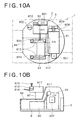
- the present fifth embodiment which has been made focusing on this point, will hereinafter be described with reference to Figs. 9A and 9B as well as Figs. 10A and 10B. It is noted that the left side in Figs. 9A and 10A corresponds to front side, the right side to rear side, the upper side to right side, and the lower side to left side, and for the sake of convenience, the same numerals are assigned to components in common with those in the third and fourth embodiments above to omit redundant descriptions as much as possible.
- a hydraulic pump (P) 807, an engine (E/G) 81 as a power source, and a radiator (R/D) 808 and an oil cooler (O/C) 809 as cooling devices are disposed in a line from the left to right side in this order as rear row devices in the rear section of the rotating frame 8, as is the case with the third embodiment above.
- a hydraulic oil tank (H/T) 82 and a control valve (C/V) 801 are disposed in a line in this order on the right side of a swivel joint (S/J) 804, while on the left side thereof a fuel tank (F/T) 86 as front row devices.
- the numeral 85 indicates an air conditioner (A/C), 802 a manipulation pattern switching valve (M/V), 803 a swinging motor (S/M), 805 a battery (BAT), and 810 a solenoid valve (S/V) as an operation lock valve.
- A/C air conditioner
- M/V manipulation pattern switching valve
- S/M swinging motor
- BAT battery
- S/V solenoid valve
- the battery 805 is disposed on the left outside of the fuel tank 86.
- the battery 805 is disposed on the left outside of the fuel tank 86.
- the fuel tank 86 is less often maintained than the battery 805, the arrangement above is found to be effective.
- the air conditioner 85 is arranged over the floor 84 of the cabin 83, for example, in a seat stand 87.
- the space under the floor 84 can be used more effectively, that is, for example, the volume of the fuel tank 86 can be increased.
- the air conditioner 85 may be arranged at the ceiling part of the cabin 83, being not limited particularly within the seat stand 87. In this case, major devices can be arranged under the floor 84, whereby the volume of the fuel tank 86 can be increased.
- the swinging motor 803 is arranged in front of the swivel joint 804.
- the space between the hydraulic oil tank 82, which is enlarged longitudinally to increase the volume thereof, and the fuel tank 86 can be used more effectively.
- the swinging motor 803 may be arranged in rear of the swivel joint 804.
- the fuel tank 86 is formed into an L shape when viewed vertically by depressing the part where the battery 805 is to be arranged at the left outer side in the rotating frame 8.
- the hydraulic pump 807 is to be located in rear of the fuel tank 86.
- an oil filler port 811 extends up to the outer peripheral wall of the rotating frame 8, which allows fueling of the tank.
- the blank space over the hydraulic pump 807 can be used effectively.
- the manipulation pattern switching valve 802 which is adapted to switch the motion pattern of actuators (not shown in the figure) for the operation of an operating lever 815 (refer to Fig. 10B) as an operation means among multiple selective motion patterns, is disposed in front of the hydraulic oil tank 82.
- the solenoid valve 810 is adapted to lock the foregoing actuators hydraulically to be inoperative, the solenoid valve 810 being disposed in the vicinity of the hydraulic oil tank 82 in front of the control valve 801.
- elements having switching portions can be arranged around the control valve 810 in a concentrated manner, which makes it possible to perform maintenance in a lump from the same place.
- a suction pipe 812 that communicates the hydraulic pump 807 and the control valve 801 is guided under the floor 84, while pilot pipes 813 that communicate the control valve 801 and pilot valves (P/V) 814 disposed over the floor 84 are guided over the floor 84.
- P/V pilot valves
- an arrangement of the pipes in the space under the floor 84 can be formed simply.
- the numeral 815 is an operating lever adapted to operate actuators in accordance with a desired motion pattern by switching the manipulation pattern switching valve 802 in advance so that the actuators operate in accordance with the desired motion pattern among multiple selective motion patterns. This allows operators to operate actuators in accordance with desired motion patterns easily.
- the numeral 816 indicates an operation lock lever adapted to be operated to turn the solenoid valve 810 on to close the pilot pipes 813. This allows actuators to be inoperative safely when operators get out of the cabin 83. However, a main pipe not shown in the figure may be closed instead of the pilot pipes 813.
- suction pipe 812 that communicates the hydraulic pump 807 and the hydraulic oil tank 82 and a delivery pipe (not shown in the figure, but can be guided along the suction pipe) that communicates the hydraulic pump 807 and the control valve 801 between the rear row devices and the front row devices almost linearly, whereby the arrangement of pipes is facilitated, and while the length of the pipes is increased in comparison with the fourth embodiment above, pressure loss in the pipes can be reduced due to the linear arrangement.
- the suction pipe 812 has a large diameter, and therefore arranging the pipe with less number of bends has advantages in terms of ensuring the easiness of the arrangement and reducing pressure loss.
- the rotating frame 8 is formed into a substantially circular shape, as mentioned above, to obtain as much an arrangement space for devices on the upper rotating frame 2 as possible, the size of the control valve 801, in accordance with the present fifth embodiment, disposed on the outside of the hydraulic oil tank 82 that requires a large space is relatively small, whereby the control valve 801 can be arranged along the arc-shape of the rotating frame 8, improving the usability of the space.
- the fuel tank 86 is arranged under the floor 84, which allows effective use of the arrangement space for devices on the upper rotating body 2.
- the hydraulic oil tank 82 is arranged between the floor 84 of the cabin 83 and the control valve 801, whereby noises such as working oil flowing sound and restricting sound from such as flowing and squeezing sound the control valve 801 can be blocked out so as not to reach operators in the cabin 83 and not to reduce the comfort therein.
- the solenoid valve 810 may be arranged in rear of the control valve 801, while the battery 805 may be arranged at the left end in rear side of the fuel tank 86, where depression of the fuel tank 86 is to be formed in accordance with the arrangement of the devices.
- the radiator 808 as a cooling device becomes unnecessary.
- the radiator 808 and the oil cooler 809 may also be arranged on a single plane together.
- the fuel tank 86 comprising an extension portion that extends to the front surface side of the air conditioner 85 in the first embodiment can be adopted to the second to fourth embodiments, and in this case, synergic advantages can be offered.
- the present invention is useful for a small swing type excavator in which an upper rotating body rotates in such a condition that the rear end thereof hardly projects outside the width of a lower traveling body, and is also suitable for a small swing type excavator in which a working device is attached pivotedly at the front end of an upper rotating body.
Landscapes
- Engineering & Computer Science (AREA)
- Structural Engineering (AREA)
- General Engineering & Computer Science (AREA)
- Civil Engineering (AREA)
- Mining & Mineral Resources (AREA)
- Mechanical Engineering (AREA)
- Chemical & Material Sciences (AREA)
- Transportation (AREA)
- Combustion & Propulsion (AREA)
- Life Sciences & Earth Sciences (AREA)
- Sustainable Energy (AREA)
- Sustainable Development (AREA)
- Cooling, Air Intake And Gas Exhaust, And Fuel Tank Arrangements In Propulsion Units (AREA)
- Body Structure For Vehicles (AREA)
- Component Parts Of Construction Machinery (AREA)
- Lubricants (AREA)
Applications Claiming Priority (7)
| Application Number | Priority Date | Filing Date | Title |
|---|---|---|---|
| JP2002085313A JP3952819B2 (ja) | 2002-03-26 | 2002-03-26 | 小旋回型ショベル |
| JP2002085313 | 2002-03-26 | ||
| JP2002085314 | 2002-03-26 | ||
| JP2002085314 | 2002-03-26 | ||
| JP2002089140A JP4003503B2 (ja) | 2002-03-27 | 2002-03-27 | 小旋回型ショベル |
| JP2002089140 | 2002-03-27 | ||
| PCT/JP2003/003391 WO2003080945A1 (fr) | 2002-03-26 | 2003-03-20 | Petite pelle mecanique a balancier |
Publications (3)
| Publication Number | Publication Date |
|---|---|
| EP1489234A1 true EP1489234A1 (fr) | 2004-12-22 |
| EP1489234A4 EP1489234A4 (fr) | 2008-04-02 |
| EP1489234B1 EP1489234B1 (fr) | 2012-02-29 |
Family
ID=28457581
Family Applications (1)
| Application Number | Title | Priority Date | Filing Date |
|---|---|---|---|
| EP03744998A Expired - Lifetime EP1489234B1 (fr) | 2002-03-26 | 2003-03-20 | Petite pelle mecanique a balancier |
Country Status (6)
| Country | Link |
|---|---|
| US (1) | US7523804B2 (fr) |
| EP (1) | EP1489234B1 (fr) |
| CN (1) | CN100402762C (fr) |
| AT (1) | ATE547570T1 (fr) |
| AU (1) | AU2003220929A1 (fr) |
| WO (1) | WO2003080945A1 (fr) |
Cited By (1)
| Publication number | Priority date | Publication date | Assignee | Title |
|---|---|---|---|---|
| EP2687636A4 (fr) * | 2011-03-17 | 2014-08-06 | Hitachi Construction Machinery | Structure de fixation de réservoir de carburant pour machine de construction |
Families Citing this family (24)
| Publication number | Priority date | Publication date | Assignee | Title |
|---|---|---|---|---|
| US20070131466A1 (en) * | 2005-12-12 | 2007-06-14 | Gutzwiller Timothy M | Work machine with electrical and hydraulic service centers |
| JP2008063114A (ja) * | 2006-09-08 | 2008-03-21 | Toyota Industries Corp | ハイブリッド産業車両 |
| JP4941089B2 (ja) * | 2007-05-15 | 2012-05-30 | コベルコ建機株式会社 | 上部旋回体及びこれを備えた建設機械 |
| WO2009017076A1 (fr) * | 2007-08-02 | 2009-02-05 | Hitachi Construction Machinery Co., Ltd. | Machine de construction |
| US8697992B2 (en) | 2008-02-01 | 2014-04-15 | Schlumberger Technology Corporation | Extended length cable assembly for a hydrocarbon well application |
| JP4686565B2 (ja) * | 2008-03-31 | 2011-05-25 | 株式会社クボタ | 作業機の上部構造 |
| DE202008013896U1 (de) * | 2008-10-17 | 2010-03-11 | Liebherr-Hydraulikbagger Gmbh | Verfahrbares Arbeitsgerät |
| JP4941571B2 (ja) * | 2010-03-18 | 2012-05-30 | コベルコ建機株式会社 | 建設機械のポンプサクション配管構造 |
| JP5562777B2 (ja) * | 2010-09-16 | 2014-07-30 | 日立建機株式会社 | 建設機械 |
| KR101831390B1 (ko) * | 2010-11-29 | 2018-02-22 | 가부시키가이샤 히다치 겡키 티에라 | 건설기계 |
| JP5780078B2 (ja) * | 2011-09-16 | 2015-09-16 | コベルコ建機株式会社 | 建設機械 |
| JP5831111B2 (ja) * | 2011-10-03 | 2015-12-09 | コベルコ建機株式会社 | 建設機械の排気構造 |
| NL2008634C2 (nl) * | 2012-04-13 | 2013-10-16 | Hudson Bay Holding B V | Mobiele inrichting. |
| US8857557B2 (en) * | 2013-03-13 | 2014-10-14 | Komatsu Ltd. | Work vehicle |
| CN103255796A (zh) * | 2013-04-09 | 2013-08-21 | 常熟建工建设集团有限公司苏州分公司 | 一种新型稳定的挖掘机回转平台 |
| WO2015005516A1 (fr) * | 2013-07-12 | 2015-01-15 | 볼보 컨스트럭션 이큅먼트 에이비 | Structure pour protéger une soupape de commande principale pour engin de chantier |
| JP5942974B2 (ja) * | 2013-12-20 | 2016-06-29 | コベルコ建機株式会社 | 建設機械 |
| CN104802866B (zh) * | 2015-02-02 | 2017-01-18 | 星光农机股份有限公司 | 一种履带式自走旋耕机 |
| KR102088805B1 (ko) * | 2017-06-27 | 2020-03-13 | 가부시키가이샤 고마쓰 세이사쿠쇼 | 작업 기계 |
| US11021053B2 (en) * | 2018-10-12 | 2021-06-01 | Deere & Company | Work vehicle with commodity tank and a commodity tank for a work vehicle |
| US11447056B2 (en) | 2020-02-28 | 2022-09-20 | Deere & Company | Work vehicle with support device for mounting a commodity tank and support device mounting a commodity tank to a work vehicle |
| USD967870S1 (en) | 2020-02-28 | 2022-10-25 | Deere & Company | Commodity tank for a work vehicle |
| US20240300588A1 (en) * | 2023-03-10 | 2024-09-12 | Manitou Equipment America, Llc | Footwell debris removal apparatus and method |
| EP4729700A1 (fr) * | 2023-06-16 | 2026-04-22 | Volvo Construction Equipment AB | Petite excavatrice électrique |
Family Cites Families (43)
| Publication number | Priority date | Publication date | Assignee | Title |
|---|---|---|---|---|
| JPH0280170A (ja) | 1988-09-17 | 1990-03-20 | Fuji Electric Co Ltd | 噴流式はんだ付け装置 |
| JP2653878B2 (ja) * | 1989-04-21 | 1997-09-17 | ヤンマーディーゼル株式会社 | 掘削作業車 |
| JP2895283B2 (ja) | 1991-10-31 | 1999-05-24 | ヤンマーディーゼル株式会社 | 旋回作業車のボンネット構造 |
| JPH06320962A (ja) * | 1993-05-17 | 1994-11-22 | Yanmar Diesel Engine Co Ltd | 旋回作業車 |
| JPH0718698A (ja) | 1993-06-30 | 1995-01-20 | Kubota Corp | バックホウ |
| JPH0721640A (ja) | 1993-06-30 | 1995-01-24 | Sony Corp | 電子機器用弾性押圧体及び電子機器 |
| JPH0726438A (ja) | 1993-07-13 | 1995-01-27 | Toray Ind Inc | 洗浄機構付き糸条交絡処理装置及び製糸工程における糸条交絡処理装置の自動洗浄方法 |
| JP3377273B2 (ja) | 1993-12-28 | 2003-02-17 | 株式会社小松製作所 | 燃料タンク構造 |
| JP3263528B2 (ja) * | 1994-06-22 | 2002-03-04 | ヤンマーディーゼル株式会社 | 旋回式掘削機 |
| JPH08246500A (ja) | 1995-03-14 | 1996-09-24 | Yutani Heavy Ind Ltd | 油圧作業機 |
| JP3294100B2 (ja) | 1996-03-29 | 2002-06-17 | 株式会社クボタ | バックホウ |
| JP3320980B2 (ja) | 1996-05-30 | 2002-09-03 | コベルコ建機株式会社 | キャブの空調装置 |
| JPH1030255A (ja) * | 1996-07-15 | 1998-02-03 | Komatsu Ltd | 油圧ショベルの作動油タンク |
| JPH10168942A (ja) * | 1996-12-11 | 1998-06-23 | Hitachi Constr Mach Co Ltd | 旋回式作業機械 |
| US6170588B1 (en) * | 1997-06-03 | 2001-01-09 | Hitachi Construction Machinery Co., Ltd. | Revolving construction machine |
| JP3261611B2 (ja) | 1997-07-01 | 2002-03-04 | 住友建機製造株式会社 | 建設機械のキャブ用送風装置 |
| JP3354845B2 (ja) | 1997-09-04 | 2002-12-09 | 株式会社クボタ | 旋回作業機 |
| JP3311970B2 (ja) | 1997-09-04 | 2002-08-05 | 株式会社クボタ | 旋回作業機 |
| JP3311971B2 (ja) | 1997-09-04 | 2002-08-05 | 株式会社クボタ | 旋回作業機 |
| CN1093609C (zh) * | 1997-09-19 | 2002-10-30 | 日立建机株式会社 | 建筑机械的冷却装置及建筑机械 |
| JP3589561B2 (ja) | 1998-01-09 | 2004-11-17 | コベルコ建機株式会社 | 建設機械の上部旋回体 |
| JP3464141B2 (ja) | 1998-03-24 | 2003-11-05 | 株式会社クボタ | 旋回作業機 |
| JP3459352B2 (ja) | 1998-03-24 | 2003-10-20 | 株式会社クボタ | 旋回作業機 |
| JP3464142B2 (ja) * | 1998-03-24 | 2003-11-05 | 株式会社クボタ | 旋回作業機 |
| JP3403632B2 (ja) | 1998-03-24 | 2003-05-06 | 株式会社クボタ | 旋回作業機 |
| JP3403633B2 (ja) | 1998-03-25 | 2003-05-06 | 株式会社クボタ | 旋回作業機 |
| JP3464144B2 (ja) | 1998-03-25 | 2003-11-05 | 株式会社クボタ | 旋回作業機 |
| JP2000054429A (ja) | 1998-08-11 | 2000-02-22 | Hokuetsu Kogyo Co Ltd | 油圧作業機 |
| EP1146174B1 (fr) * | 1998-08-31 | 2009-10-07 | Yanmar Co., Ltd. | Machine de terrassement a tres petit pivotement |
| JP2000107932A (ja) | 1998-10-05 | 2000-04-18 | Amada Co Ltd | 送りバイス装置の油圧回路 |
| JP2000109801A (ja) | 1998-10-08 | 2000-04-18 | Hitachi Chem Co Ltd | Cmp研磨剤及び基板の研磨方法 |
| JP3300761B2 (ja) | 1999-07-13 | 2002-07-08 | 日本▲まき▼線工業株式会社 | 定電圧電源 |
| JP3418361B2 (ja) * | 1999-08-19 | 2003-06-23 | 株式会社小松製作所 | 作業車両の運転室空気調和装置の取付構造 |
| JP2001059237A (ja) | 1999-08-20 | 2001-03-06 | Hitachi Constr Mach Co Ltd | 旋回式建設機械 |
| JP3399416B2 (ja) * | 1999-10-07 | 2003-04-21 | コベルコ建機株式会社 | 建設機械の冷却構造 |
| JP3679286B2 (ja) * | 1999-12-02 | 2005-08-03 | 株式会社クボタ | バックホーの温度調整装置配置構造 |
| JP2001271378A (ja) | 2000-03-23 | 2001-10-05 | Kubota Corp | 旋回作業機 |
| JP2001288788A (ja) | 2000-04-04 | 2001-10-19 | Toto Ltd | 放水機器の残水垂れ防止方法、残水垂れ防止性放水機器、並びに残水垂れ防止性放水機器用コーティング組成物 |
| JP2001288778A (ja) * | 2000-04-10 | 2001-10-19 | Komatsu Ltd | 建設機械 |
| JP2001295319A (ja) | 2000-04-11 | 2001-10-26 | Hitachi Constr Mach Co Ltd | 建設機械の空調装置 |
| JP2001303616A (ja) * | 2000-04-21 | 2001-10-31 | Sumitomo (Shi) Construction Machinery Manufacturing Co Ltd | 建設機械の燃料−作動油タンク |
| JP2001323500A (ja) * | 2000-05-15 | 2001-11-22 | Kubota Corp | 旋回作業機 |
| US7021074B2 (en) * | 2003-03-10 | 2006-04-04 | Kubota Corporation | Work vehicle |
-
2003
- 2003-03-20 AU AU2003220929A patent/AU2003220929A1/en not_active Abandoned
- 2003-03-20 US US10/506,615 patent/US7523804B2/en not_active Expired - Fee Related
- 2003-03-20 EP EP03744998A patent/EP1489234B1/fr not_active Expired - Lifetime
- 2003-03-20 AT AT03744998T patent/ATE547570T1/de active
- 2003-03-20 WO PCT/JP2003/003391 patent/WO2003080945A1/fr not_active Ceased
- 2003-03-20 CN CNB038068540A patent/CN100402762C/zh not_active Expired - Fee Related
Cited By (2)
| Publication number | Priority date | Publication date | Assignee | Title |
|---|---|---|---|---|
| EP2687636A4 (fr) * | 2011-03-17 | 2014-08-06 | Hitachi Construction Machinery | Structure de fixation de réservoir de carburant pour machine de construction |
| US9227510B2 (en) | 2011-03-17 | 2016-01-05 | Hitachi Construction Machinery Co., Ltd. | Fuel tank affixing structure for construction machine |
Also Published As
| Publication number | Publication date |
|---|---|
| ATE547570T1 (de) | 2012-03-15 |
| US20050166429A1 (en) | 2005-08-04 |
| EP1489234A4 (fr) | 2008-04-02 |
| AU2003220929A1 (en) | 2003-10-08 |
| WO2003080945A1 (fr) | 2003-10-02 |
| CN1643223A (zh) | 2005-07-20 |
| US7523804B2 (en) | 2009-04-28 |
| CN100402762C (zh) | 2008-07-16 |
| EP1489234B1 (fr) | 2012-02-29 |
Similar Documents
| Publication | Publication Date | Title |
|---|---|---|
| US7523804B2 (en) | Small swing type shovel | |
| JP5580681B2 (ja) | 電動作業車両 | |
| WO2002040782A1 (fr) | Engin de terrassement | |
| JP2003328391A (ja) | 旋回作業機の油圧配管構造 | |
| CN117403734A (zh) | 建筑机械 | |
| JP2000170209A (ja) | 建設機械用キャブ | |
| CN101631914B (zh) | 挖掘作业机 | |
| US10968599B2 (en) | Work machine | |
| JP3693480B2 (ja) | 油圧ショベルの上部旋回体 | |
| JP4003503B2 (ja) | 小旋回型ショベル | |
| JP3579297B2 (ja) | 旋回式建設機械 | |
| JP3952819B2 (ja) | 小旋回型ショベル | |
| JP2004116103A (ja) | 油圧ショベルの付属作業具油圧回路の単動―複動回路セレクタバルブの設置構造 | |
| JP2007092278A (ja) | バックホーの上部構造 | |
| JP3155443B2 (ja) | 旋回作業機の上部構造 | |
| JP3403633B2 (ja) | 旋回作業機 | |
| US20240262180A1 (en) | Support assembly for radiators of work machines | |
| JP4346428B2 (ja) | 旋回作業機 | |
| JP3300635B2 (ja) | 旋回式建設機械 | |
| JP2005061086A (ja) | 小型ショベル | |
| JP3659468B2 (ja) | 建設機械の作業灯取付構造 | |
| JP2004003298A (ja) | 後端小旋回型ショベル | |
| JP5153552B2 (ja) | 建設機械の機械室 | |
| JP2000192510A (ja) | 建設機械 | |
| JPH093972A (ja) | 作業機の機体構造 |
Legal Events
| Date | Code | Title | Description |
|---|---|---|---|
| PUAI | Public reference made under article 153(3) epc to a published international application that has entered the european phase |
Free format text: ORIGINAL CODE: 0009012 |
|
| 17P | Request for examination filed |
Effective date: 20040923 |
|
| AK | Designated contracting states |
Kind code of ref document: A1 Designated state(s): AT BE BG CH CY CZ DE DK EE ES FI FR GB GR HU IE IT LI LU MC NL PT RO SE SI SK TR |
|
| AX | Request for extension of the european patent |
Extension state: AL LT LV MK |
|
| A4 | Supplementary search report drawn up and despatched |
Effective date: 20080303 |
|
| RIC1 | Information provided on ipc code assigned before grant |
Ipc: E02F 9/00 20060101AFI20031009BHEP Ipc: B60K 15/00 20060101ALI20080226BHEP |
|
| 17Q | First examination report despatched |
Effective date: 20090430 |
|
| REG | Reference to a national code |
Ref country code: DE Ref legal event code: R079 Ref document number: 60340133 Country of ref document: DE Free format text: PREVIOUS MAIN CLASS: E02F0009000000 Ipc: E02F0009080000 |
|
| RIC1 | Information provided on ipc code assigned before grant |
Ipc: B60K 15/073 20060101ALI20110809BHEP Ipc: E02F 9/08 20060101AFI20110809BHEP Ipc: B60K 15/00 20060101ALI20110809BHEP Ipc: E02F 9/16 20060101ALI20110809BHEP |
|
| GRAP | Despatch of communication of intention to grant a patent |
Free format text: ORIGINAL CODE: EPIDOSNIGR1 |
|
| GRAS | Grant fee paid |
Free format text: ORIGINAL CODE: EPIDOSNIGR3 |
|
| GRAA | (expected) grant |
Free format text: ORIGINAL CODE: 0009210 |
|
| AK | Designated contracting states |
Kind code of ref document: B1 Designated state(s): AT BE BG CH CY CZ DE DK EE ES FI FR GB GR HU IE IT LI LU MC NL PT RO SE SI SK TR |
|
| REG | Reference to a national code |
Ref country code: GB Ref legal event code: FG4D Ref country code: CH Ref legal event code: EP |
|
| REG | Reference to a national code |
Ref country code: AT Ref legal event code: REF Ref document number: 547570 Country of ref document: AT Kind code of ref document: T Effective date: 20120315 |
|
| REG | Reference to a national code |
Ref country code: IE Ref legal event code: FG4D |
|
| REG | Reference to a national code |
Ref country code: DE Ref legal event code: R096 Ref document number: 60340133 Country of ref document: DE Effective date: 20120419 |
|
| REG | Reference to a national code |
Ref country code: NL Ref legal event code: VDEP Effective date: 20120229 |
|
| PG25 | Lapsed in a contracting state [announced via postgrant information from national office to epo] |
Ref country code: NL Free format text: LAPSE BECAUSE OF FAILURE TO SUBMIT A TRANSLATION OF THE DESCRIPTION OR TO PAY THE FEE WITHIN THE PRESCRIBED TIME-LIMIT Effective date: 20120229 |
|
| PG25 | Lapsed in a contracting state [announced via postgrant information from national office to epo] |
Ref country code: PT Free format text: LAPSE BECAUSE OF FAILURE TO SUBMIT A TRANSLATION OF THE DESCRIPTION OR TO PAY THE FEE WITHIN THE PRESCRIBED TIME-LIMIT Effective date: 20120629 Ref country code: FI Free format text: LAPSE BECAUSE OF FAILURE TO SUBMIT A TRANSLATION OF THE DESCRIPTION OR TO PAY THE FEE WITHIN THE PRESCRIBED TIME-LIMIT Effective date: 20120229 Ref country code: BE Free format text: LAPSE BECAUSE OF FAILURE TO SUBMIT A TRANSLATION OF THE DESCRIPTION OR TO PAY THE FEE WITHIN THE PRESCRIBED TIME-LIMIT Effective date: 20120229 Ref country code: GR Free format text: LAPSE BECAUSE OF FAILURE TO SUBMIT A TRANSLATION OF THE DESCRIPTION OR TO PAY THE FEE WITHIN THE PRESCRIBED TIME-LIMIT Effective date: 20120530 |
|
| REG | Reference to a national code |
Ref country code: AT Ref legal event code: MK05 Ref document number: 547570 Country of ref document: AT Kind code of ref document: T Effective date: 20120229 |
|
| PG25 | Lapsed in a contracting state [announced via postgrant information from national office to epo] |
Ref country code: CY Free format text: LAPSE BECAUSE OF FAILURE TO SUBMIT A TRANSLATION OF THE DESCRIPTION OR TO PAY THE FEE WITHIN THE PRESCRIBED TIME-LIMIT Effective date: 20120229 |
|
| PG25 | Lapsed in a contracting state [announced via postgrant information from national office to epo] |
Ref country code: CZ Free format text: LAPSE BECAUSE OF FAILURE TO SUBMIT A TRANSLATION OF THE DESCRIPTION OR TO PAY THE FEE WITHIN THE PRESCRIBED TIME-LIMIT Effective date: 20120229 Ref country code: MC Free format text: LAPSE BECAUSE OF NON-PAYMENT OF DUE FEES Effective date: 20120331 Ref country code: SE Free format text: LAPSE BECAUSE OF FAILURE TO SUBMIT A TRANSLATION OF THE DESCRIPTION OR TO PAY THE FEE WITHIN THE PRESCRIBED TIME-LIMIT Effective date: 20120229 Ref country code: RO Free format text: LAPSE BECAUSE OF FAILURE TO SUBMIT A TRANSLATION OF THE DESCRIPTION OR TO PAY THE FEE WITHIN THE PRESCRIBED TIME-LIMIT Effective date: 20120229 Ref country code: SI Free format text: LAPSE BECAUSE OF FAILURE TO SUBMIT A TRANSLATION OF THE DESCRIPTION OR TO PAY THE FEE WITHIN THE PRESCRIBED TIME-LIMIT Effective date: 20120229 Ref country code: DK Free format text: LAPSE BECAUSE OF FAILURE TO SUBMIT A TRANSLATION OF THE DESCRIPTION OR TO PAY THE FEE WITHIN THE PRESCRIBED TIME-LIMIT Effective date: 20120229 Ref country code: EE Free format text: LAPSE BECAUSE OF FAILURE TO SUBMIT A TRANSLATION OF THE DESCRIPTION OR TO PAY THE FEE WITHIN THE PRESCRIBED TIME-LIMIT Effective date: 20120229 |
|
| REG | Reference to a national code |
Ref country code: CH Ref legal event code: PL |
|
| PG25 | Lapsed in a contracting state [announced via postgrant information from national office to epo] |
Ref country code: SK Free format text: LAPSE BECAUSE OF FAILURE TO SUBMIT A TRANSLATION OF THE DESCRIPTION OR TO PAY THE FEE WITHIN THE PRESCRIBED TIME-LIMIT Effective date: 20120229 Ref country code: IT Free format text: LAPSE BECAUSE OF FAILURE TO SUBMIT A TRANSLATION OF THE DESCRIPTION OR TO PAY THE FEE WITHIN THE PRESCRIBED TIME-LIMIT Effective date: 20120229 |
|
| REG | Reference to a national code |
Ref country code: IE Ref legal event code: MM4A |
|
| PLBE | No opposition filed within time limit |
Free format text: ORIGINAL CODE: 0009261 |
|
| STAA | Information on the status of an ep patent application or granted ep patent |
Free format text: STATUS: NO OPPOSITION FILED WITHIN TIME LIMIT |
|
| REG | Reference to a national code |
Ref country code: DE Ref legal event code: R119 Ref document number: 60340133 Country of ref document: DE Effective date: 20121002 |
|
| GBPC | Gb: european patent ceased through non-payment of renewal fee |
Effective date: 20120529 |
|
| PG25 | Lapsed in a contracting state [announced via postgrant information from national office to epo] |
Ref country code: LI Free format text: LAPSE BECAUSE OF NON-PAYMENT OF DUE FEES Effective date: 20120331 Ref country code: AT Free format text: LAPSE BECAUSE OF FAILURE TO SUBMIT A TRANSLATION OF THE DESCRIPTION OR TO PAY THE FEE WITHIN THE PRESCRIBED TIME-LIMIT Effective date: 20120229 Ref country code: IE Free format text: LAPSE BECAUSE OF NON-PAYMENT OF DUE FEES Effective date: 20120320 Ref country code: CH Free format text: LAPSE BECAUSE OF NON-PAYMENT OF DUE FEES Effective date: 20120331 |
|
| 26N | No opposition filed |
Effective date: 20121130 |
|
| REG | Reference to a national code |
Ref country code: FR Ref legal event code: ST Effective date: 20130104 |
|
| PG25 | Lapsed in a contracting state [announced via postgrant information from national office to epo] |
Ref country code: FR Free format text: LAPSE BECAUSE OF NON-PAYMENT OF DUE FEES Effective date: 20120430 |
|
| PG25 | Lapsed in a contracting state [announced via postgrant information from national office to epo] |
Ref country code: GB Free format text: LAPSE BECAUSE OF NON-PAYMENT OF DUE FEES Effective date: 20120529 Ref country code: ES Free format text: LAPSE BECAUSE OF FAILURE TO SUBMIT A TRANSLATION OF THE DESCRIPTION OR TO PAY THE FEE WITHIN THE PRESCRIBED TIME-LIMIT Effective date: 20120609 |
|
| PG25 | Lapsed in a contracting state [announced via postgrant information from national office to epo] |
Ref country code: BG Free format text: LAPSE BECAUSE OF FAILURE TO SUBMIT A TRANSLATION OF THE DESCRIPTION OR TO PAY THE FEE WITHIN THE PRESCRIBED TIME-LIMIT Effective date: 20120529 |
|
| PG25 | Lapsed in a contracting state [announced via postgrant information from national office to epo] |
Ref country code: TR Free format text: LAPSE BECAUSE OF FAILURE TO SUBMIT A TRANSLATION OF THE DESCRIPTION OR TO PAY THE FEE WITHIN THE PRESCRIBED TIME-LIMIT Effective date: 20120229 |
|
| PG25 | Lapsed in a contracting state [announced via postgrant information from national office to epo] |
Ref country code: LU Free format text: LAPSE BECAUSE OF NON-PAYMENT OF DUE FEES Effective date: 20120320 |
|
| PG25 | Lapsed in a contracting state [announced via postgrant information from national office to epo] |
Ref country code: HU Free format text: LAPSE BECAUSE OF FAILURE TO SUBMIT A TRANSLATION OF THE DESCRIPTION OR TO PAY THE FEE WITHIN THE PRESCRIBED TIME-LIMIT Effective date: 20030320 |
|
| PG25 | Lapsed in a contracting state [announced via postgrant information from national office to epo] |
Ref country code: DE Free format text: LAPSE BECAUSE OF FAILURE TO SUBMIT A TRANSLATION OF THE DESCRIPTION OR TO PAY THE FEE WITHIN THE PRESCRIBED TIME-LIMIT Effective date: 20121002 |