EP1489389A2 - Elektrisches Bauteil, insbesondere Positionssensor - Google Patents
Elektrisches Bauteil, insbesondere Positionssensor Download PDFInfo
- Publication number
- EP1489389A2 EP1489389A2 EP04012679A EP04012679A EP1489389A2 EP 1489389 A2 EP1489389 A2 EP 1489389A2 EP 04012679 A EP04012679 A EP 04012679A EP 04012679 A EP04012679 A EP 04012679A EP 1489389 A2 EP1489389 A2 EP 1489389A2
- Authority
- EP
- European Patent Office
- Prior art keywords
- wires
- component according
- guide channels
- cable
- guide
- Prior art date
- Legal status (The legal status is an assumption and is not a legal conclusion. Google has not performed a legal analysis and makes no representation as to the accuracy of the status listed.)
- Withdrawn
Links
- 239000004020 conductor Substances 0.000 claims abstract description 19
- 238000003780 insertion Methods 0.000 claims abstract description 19
- 230000037431 insertion Effects 0.000 claims abstract description 19
- 239000000463 material Substances 0.000 claims description 15
- 239000000853 adhesive Substances 0.000 claims description 9
- 230000001070 adhesive effect Effects 0.000 claims description 9
- 238000005192 partition Methods 0.000 claims description 5
- 239000000945 filler Substances 0.000 claims description 2
- 238000011144 upstream manufacturing Methods 0.000 claims description 2
- 238000011156 evaluation Methods 0.000 abstract description 2
- 210000003462 vein Anatomy 0.000 description 9
- 238000013461 design Methods 0.000 description 6
- 238000004519 manufacturing process Methods 0.000 description 6
- 238000000034 method Methods 0.000 description 4
- 238000009826 distribution Methods 0.000 description 3
- 238000001746 injection moulding Methods 0.000 description 3
- 230000004308 accommodation Effects 0.000 description 2
- 238000004026 adhesive bonding Methods 0.000 description 2
- 230000015572 biosynthetic process Effects 0.000 description 2
- 238000002347 injection Methods 0.000 description 2
- 239000007924 injection Substances 0.000 description 2
- 230000001681 protective effect Effects 0.000 description 2
- 238000000926 separation method Methods 0.000 description 2
- ATJFFYVFTNAWJD-UHFFFAOYSA-N Tin Chemical compound [Sn] ATJFFYVFTNAWJD-UHFFFAOYSA-N 0.000 description 1
- 230000000295 complement effect Effects 0.000 description 1
- 238000001514 detection method Methods 0.000 description 1
- 238000011161 development Methods 0.000 description 1
- 238000005538 encapsulation Methods 0.000 description 1
- 238000005516 engineering process Methods 0.000 description 1
- 230000009969 flowable effect Effects 0.000 description 1
- 239000012530 fluid Substances 0.000 description 1
- 238000009434 installation Methods 0.000 description 1
- 230000003993 interaction Effects 0.000 description 1
- 239000002184 metal Substances 0.000 description 1
- 238000001465 metallisation Methods 0.000 description 1
- 239000002991 molded plastic Substances 0.000 description 1
- 230000000149 penetrating effect Effects 0.000 description 1
- 230000002093 peripheral effect Effects 0.000 description 1
- 238000003825 pressing Methods 0.000 description 1
- 230000000630 rising effect Effects 0.000 description 1
- 229910000679 solder Inorganic materials 0.000 description 1
- 239000000243 solution Substances 0.000 description 1
Images



Classifications
-
- H—ELECTRICITY
- H01—ELECTRIC ELEMENTS
- H01R—ELECTRICALLY-CONDUCTIVE CONNECTIONS; STRUCTURAL ASSOCIATIONS OF A PLURALITY OF MUTUALLY-INSULATED ELECTRICAL CONNECTING ELEMENTS; COUPLING DEVICES; CURRENT COLLECTORS
- H01R13/00—Details of coupling devices of the kinds covered by groups H01R12/70 or H01R24/00 - H01R33/00
- H01R13/58—Means for relieving strain on wire connection, e.g. cord grip, for avoiding loosening of connections between wires and terminals within a coupling device terminating a cable
- H01R13/5845—Means for relieving strain on wire connection, e.g. cord grip, for avoiding loosening of connections between wires and terminals within a coupling device terminating a cable the strain relief being achieved by molding parts around cable and connections
-
- G—PHYSICS
- G01—MEASURING; TESTING
- G01D—MEASURING NOT SPECIALLY ADAPTED FOR A SPECIFIC VARIABLE; ARRANGEMENTS FOR MEASURING TWO OR MORE VARIABLES NOT COVERED IN A SINGLE OTHER SUBCLASS; TARIFF METERING APPARATUS; MEASURING OR TESTING NOT OTHERWISE PROVIDED FOR
- G01D11/00—Component parts of measuring arrangements not specially adapted for a specific variable
- G01D11/24—Housings ; Casings for instruments
- G01D11/245—Housings for sensors
-
- H—ELECTRICITY
- H01—ELECTRIC ELEMENTS
- H01R—ELECTRICALLY-CONDUCTIVE CONNECTIONS; STRUCTURAL ASSOCIATIONS OF A PLURALITY OF MUTUALLY-INSULATED ELECTRICAL CONNECTING ELEMENTS; COUPLING DEVICES; CURRENT COLLECTORS
- H01R4/00—Electrically-conductive connections between two or more conductive members in direct contact, i.e. touching one another; Means for effecting or maintaining such contact; Electrically-conductive connections having two or more spaced connecting locations for conductors and using contact members penetrating insulation
- H01R4/02—Soldered or welded connections
- H01R4/023—Soldered or welded connections between cables or wires and terminals
Definitions
- MID Molded Interconnect Device
- EP 1101667 A2 proposes one-piece connecting pins on the carrier element of a MID carrier to form and metallize. This can however, only a connector with a complementary Connector counterpart are manufactured.
- the connector body has several adjacent guide channels, through which the wires of the cable to be contacted can be inserted are and their channel walls guide surfaces form that diverge in the direction of insertion of the wires, that the veins spread apart when inserted be, and that the circuit carrier is in extension of the guide channels at their outlet mouths, contacting areas connected to the conductor tracks has, on which the cores by means of a contact material attachable or attached in an electrically conductive manner are, the longitudinal course of the guide surfaces so formed is that they veins when exiting the guide channels at least approximately to the longitudinal plant on the subsequent contact surfaces.
- the cable When assembling the electrical component, the cable can be used ahead of its cores freed from the cable sheath into the connector body to be inserted, with the wires in the guide channels occur and due to the divergent course the guide surfaces are spread apart.
- the in Original state will be very close to each other in this way automatically placed at a distance from each other, the secure contact with sufficiently large Allows contact areas.
- Another advantage is that the veins through the appropriately designed guide surfaces purposefully in a position alongside the Contacting areas are routed so that they with the Contacting areas preferably in direct contact arrive or are at least only minimally spaced.
- the one with the guide channels with the guide surfaces Connection body is advantageously in one piece with the Conductor tracks and possibly also carrying electronic components Carrier element of the circuit carrier formed so that a joint production as part of an injection molding process is possible.
- the cable comes with its wires in a direction of insertion into the connector body introduced, this insertion direction and a right angle Transverse direction a main plane of the circuit carrier define containing main body.
- the contacting surfaces are expediently oriented in such a way that that their surface course with the exit direction the veins emerging from the guide channels coincide.
- the contacting areas close in particular steplessly to the guide surfaces.
- the contacting areas at least partially in one expansion plane parallel to the aforementioned main plane to be arranged or, for example, also in a direction of insertion, especially in the manner of a ramp, rising Expansion level.
- the contact surfaces can also be arranged that they are at least partially in a cross and preferably perpendicular to the main plane defined above Expansion plane lie so that they flank the veins laterally.
- a reliable mutual separation of the contacting zones is achieved and thus the formation of short circuits reliably prevented during the contacting process if between contacting areas adjacent in the transverse direction on the carrier element of the circuit carrier carrying the conductor tracks trained partitions are provided.
- the leadership channels expediently in the area of their entry openings provided with appropriate lead-in chamfers.
- the connector body is provided with a recess provided that receives the end portion of the cable jacket and their wall from a laterally opening adhesive channel is penetrated, for the introduction of adhesive serves, which, due to capillary action, around the cable jacket around an adhesive connection between the cable jacket and the Creates inner surface of the receiving recess.
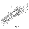
- the exemplary embodiments show electrical components 1 in one exemplary configuration as position sensors.
- the invention can also be used on any realize other electrical components, for example when contacting electrical valve actuators such as Electromagnets or piezo actuators.
- electrical valve actuators such as Electromagnets or piezo actuators.
- electrical Component is a component that is to be understood with electrical and / or is equipped with electronic components.
- the position sensor 1 has an elongated, in particular Functional part 2 designed like a beam, to which a Cable 3 is connected.
- the functional part 2 has one Longitudinal axis 4 and, oriented in the direction of the longitudinal axis 4, a front 5 and a back 6.
- the cable 6 goes on the back, in axial extension, from the functional part 2 from.
- the position sensor 1 is particularly suitable for installation a linear actuator provided to a predetermined position to detect the drive part of this linear drive.
- the drive part is activated by the application of fluid actable piston.
- the position detection happens contactless and based on the interaction of one arranged on the drive part actuator a sensor element 7 arranged in the functional part 2.
- the functional part 2 has an elongated, housing-like trained main body 8, which consists of an elongated Circuit carrier 12 and one with this in the area of the back 6 permanently connected connector body 13.
- MID Molded Interconnect Device
- the above-mentioned longitudinal axis 4 is also the Longitudinal axis of the circuit board 12.
- the circuit carrier 12 contains an elongated carrier element 14 made of injection molded plastic material. It forms the supporting structure of the functional part 2 and acts simultaneously as a carrier for the circuit mentioned and the associated electrical and / or electronic components.
- the circuit includes several on the surface of the carrier element 14 running conductor tracks 15, among others serve, possibly with the interposition of electronic Components, the electrically conductive wires 16 of the cable 3 with the sensor element 7 and possibly other electronic components to connect the circuit electrically.
- Educated are the conductor tracks 15 from one to the carrier element 14 applied structured metal layer. The production happens, for example, through large-area metallization of the carrier element previously produced by injection molding 14 with subsequent structuring by galvanic Treatment. It is particularly advantageous that this MID technology easily creates a three-dimensional conductor pattern can be an optimal, space-saving conductor course allows.
- the circuit carrier 12 is a have longitudinally extending recess 17 of any structure can, the components of the electrical circuit in this recess on corresponding sections of the carrier element 14 are formed.
- the recess 17 When fully assembled of the position sensor 1 is the recess 17 by a Filled filler, not shown, which the complete circuit covered and with the material of the support element 14 is integrally connected such that a hermetically sealed covering or encapsulation of the circuit belonging components is present.
- the position sensor can be connected to an electronic one Evaluation device or another electronic Device can be connected.
- the cable 3 contains several of the already mentioned wires 16, which preferably each consist of one A large number of strands are constructed in parallel to each other Arrangement together from an insulating cable jacket 18 are enclosed.
- the individual wires 16 are each again covered by a separate protective jacket 22, so that no immediate between the cable sheath 18 and the wires 16 There is contact.
- connection body 13 already mentioned is preferably in one piece executed with the support member 14 so that it is a component of the circuit carrier 12 forms.
- the production is particularly easy in this way.
- the connector body 13 has an axially the carrier element 14 facing front 23 and an opposite back 24. Its front side 23 delimits the rear end section the recess 17, said end portion being one Contacting space 25 forms in which the electrical contact made between the wires 16 and the conductor tracks 15 is. In this contact space 25 is closed for everyone Contacting wire 16 connected to a conductor track 15 Contacting surface 26 provided in one piece contact pad connected to the corresponding conductor track 15 27 is formed, which to that by MID manufacturing realized circuit of the circuit carrier 12 belongs.
- the outer contour of that of the cable jacket 18th corresponds, so that the latter can be inserted with slight play is.
- the cable sheath 18 a circular outer contour, so that the receiving recess 28 has a circular cylindrical shape.
- the axially between the receiving recess 28 and the contacting space 25 lying front wall 32 of the connecting body 13 is of a number corresponding to the number of wires 16 penetrated by guide channels 33. They enable each the passage of a wire 16 from the receiving recess 28 to the contacting space 25.
- Each guide channel 33 has one entry mouth lying at the bottom of the receiving recess 28 34 and one on the front side facing the contacting space 25 23 of the front wall 32 lying outlet 35.
- the end sections 36 are in parallel position relatively close to each other.
- the picture shows a three-wire cable 3, in which the three wires 16 in the same Angular distance placed around the longitudinal axis 37 of the cable are.
- the cable sheath plunges with it to the front end portions 36 of the wires 16 End portion 38 coaxially into the receiving recess 28 approximately their reason.
- the upstream end sections 36 of the wires 16 each pass through one of the guide channels 33 and lie in the contacting space 25 with one or several places of its outer circumference along one of the Contacting surfaces 26.
- Each guide channel 33 is at least assigned such a contacting surface 26, the following the outlet mouth 35 of the guide channel in question 33 is arranged.
- each guide channel 33 is in the area of the inlet mouth 34 with one in the insertion direction 42 of the wires 16 or of the cable 3 tapered insertion bevel 43, which targeted insertion of the relevant wire 16 supported.
- a strain relief for the cable 3 is by gluing the Cable sheath 18 realized with the connector body 13.
- contacting space 25 is one of the number to be contacted
- Cores 16 corresponding number of contact zones 46 defines, in each of which one of the contacting areas 26 is located.
- the outlet mouths 35 each lead to one of these contacting zones 46
- Three contacting zones 46 are consequently exemplary embodiments available.
- the side-by-side penetrating the front wall 32 Guide channels 33 are designed in a special way. Your channel walls form guide surfaces 47 which in the Insert direction 42 diverge such that the wires 16 are spread apart when inserted. I'm complete inserted state of the cable 3 thus take the Veins 16 a spread apart indicated in Fig. 4 Position in which the contact surfaces 26 to contacting end portions 36 transverse to the longitudinal axis 37 a distance from each other than during the in Fig. 5 shown initial state.
- the increased distance between the wires 16 facilitates this Applying the contact material 44 and enables large electrical connection.
- Another feature that should be emphasized is that by the chosen longitudinal course of the guide surfaces 47 the veins 16 at least approximately when exiting the guide channels 33 to the longitudinal system to the next one Contacting surface 26 are performed. You can tell 2 and 3 that the surface course of the contacting surfaces 26 with the exit direction marked by an arrow 49 of the wires 16 emerging from the guide channels 33 is expediently rectified and that the contact surfaces 26 preferably steplessly to the guide surfaces 47 connect.
- the stepless design leaves itself, for example, in the material of the carrier element 14 Realize recessed accommodation of the contact pads 27.
- the end sections 36 during the insertion process after exiting the guide channels 33 automatically come into contact with the contacting surfaces 26 and until they reach their end position on the contact surfaces 26 slide along.
- the wires 16 using a tool to the contact surfaces 26 although this is for safety reasons is recommended.
- a press on the contact surfaces 26 should definitely be done if the wires 16 a position with a small distance next to or above the contact surfaces 26 should take.
- the guide channels 33 are circumferential in the embodiment closed by the material of the connector body 13. To get the desired leadership role, could they have the same cross-section over their entire length exhibit. Associated curvatures could, however Pushing through the wires 16 impair.
- the guide channels 33 are therefore like this trained to have a larger cross section than that Have cores 16 and only part of the wall for formation of the guide surfaces 47 contributes.
- the guide channels 33 with a suitably the longitudinal axis 4 coincident center axis 48 distributed around are arranged, the guide surfaces 47 of the wall sections pointing radially outward from the central axis 48 of the guide channels 33 formed.
- the guide channels 33 preferably have an elongated one Cross section with radial with respect to the center axis 48 oriented cross-sectional longitudinal axis, the channel wall with the exception of 47 in the area of the guide surfaces runs while defining the guide surfaces 47 an inclined, changing its distance from the center axis 48 Has course.
- a main level 53 which by the insertion direction 42 and a right angle thereto, in 3 transverse direction 54 perpendicular to the plane of the drawing is spanned. Looking at the arrangement in one too this main plane 53 right-angled, marked with an arrow Direction of view 56, so are the exit zones 55 of the individual management channels including those concerned adjoining contact surfaces 26 arranged side by side. In other words, the contacting zones are located 46 in the transverse direction 54 side by side.
- the contacting areas 26 of the individual contacting zones 46 as can be seen, for example, from FIG. 1, at different height levels with respect to the main level 53 lie at right angles in height 57. Thereby can be an optimal distribution of the contacting zones reach in the volume of the main body 8. It will also a possible short-circuiting flow of the Contact material 44 between adjacent contact zones 46 counteracted. As a further protective measure in this Considerations can exist between adjacent contacting zones 46 Partitions 58 can be placed, in particular in one piece with the carrier element 14 are formed and the contacting zones isolate each other.
- the contact surfaces increase 26 in relation to the insertion direction 42 in the height direction 57. Due to this oblique course a ramp-like configuration.
- the inclination can be the individual contacting zones 46 are different.
- the contacting surfaces 26 can also at least partially run in an expansion plane that is transverse and in particular runs at right angles to the main plane 53. In this Fall, they can, as shown in Fig. 2, in addition or alternatively be provided on the partition walls 58.
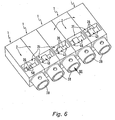
- FIGS. 6 and 7 In the position sensors shown schematically in FIGS. 6 and 7 are examples of different design options for the guide channels 33, guide surfaces 47 and Contact zones 46 illustrated. Viewed from left to right the wires 16 in the first position sensor led down by the guide surfaces 47 and on the adjoining flat contact surfaces 26 are pressed. To see there are also partition walls 58 between adjacent contacting zones 46th
- the wires 16 move upwards led, the case may arise that the end portions 36 when leaving the guide channels 33 in the already mentioned manner with a small distance above the contact surfaces 26 hover.
- the design of the third position sensor differs differs from that of the second position sensor only by that the central guide channel 33 one to the direction of insertion 42 has a parallel course, so that the wire 16 leads through is just led to the assigned contact area.
- the middle contact area has 26 a course increasing in the insertion direction, while the two outer contact surfaces 26 are parallel are aligned with the main plane 53.
- the guide channels 33 can be relatively simple by means of a single slide in one Manufacture injection molding tool, since the wires 16 no further than bent outwards up to the outer contour of the cable sheath become. With higher numbers of poles there are usually additional Levels for the accommodation of contact surfaces 26 required and / or a terrace-like distribution can take place.
- the exemplary embodiment enables electrical contacting very simply by having the contact material 44 before inserting the cable into the desired one Places applied. This simplifies the manufacturing process.
Landscapes
- Physics & Mathematics (AREA)
- General Physics & Mathematics (AREA)
- Details Of Connecting Devices For Male And Female Coupling (AREA)
- Connections By Means Of Piercing Elements, Nuts, Or Screws (AREA)
Abstract
Description
- Fig. 1
- eine mögliche Bauform des erfindungsgemäßen elektrischen Bauteils in einer Ausgestaltung als Positionssensor in einer Unteransicht, wobei zur besseren Sichtbarmachung der einzelnen Komponenten vorhandenes Füllmaterial nicht abgebildet ist,
- Fig. 2
- eine vergrößerte Darstellung des Endabschnittes des in Fig. 1 gezeigten Bauteils im Längsschnitt in perspektivischer Darstellung,
- Fig. 3
- eine Ansicht der in Fig. 3 gezeigten Anordnung mit Blick auf die Schnittebene in Richtung des Pfeils III,
- Fig. 4
- eine Einzeldarstellung des bei dem Bauteil der Fig. 1 bis 3 angeschlossenen Kabels, wobei die im angeschlossenen Zustand vorliegende auseinandergespreizte Stellung der Adern ersichtlich ist,
- Fig. 5
- das Kabel aus Fig. 4 im Ausgangszustand vor dem Einstecken in den Anschlusskörper,
- Fig. 6
- mehrere zu einer Baueinheit zusammengefasste elektrische Bauteile mit unterschiedlich ausgestalteten Kontaktierungszonen zur Verdeutlichung der Variabilität der erfindungsgemäßen Maßnahmen und
- Fig. 7
- eine Rückansicht der Anordnung aus Fig. 6 mit Blickrichtung gemäß Pfeil VII, die mit der Einsteckrichtung der nicht gezeigten Kabel übereinstimmt.
Claims (17)
- Elektrisches Bauteil, insbesondere Positionssensor, mit einem Hauptkörper (8), der einen als MID-Bauteil (MID = Moulded Interconnect Device) ausgeführten Schaltungsträger (12) und einen an dem Schaltungsträger (12) angeordneten Anschlusskörper (13) aufweist, wobei an dem Anschlusskörper (13) ein mehradriges elektrisches Kabel (3) fixierbar oder fixiert ist, dessen Adern (16) den Anschlusskörper (13) zur Kontaktierung von Leiterbahnen (15) des Schaltungsträgers (12) durchsetzen, dadurch gekennzeichnet, dass der Anschlusskörper (13) über mehrere nebeneinanderliegende Führungskanäle (33) verfügt, durch die die zu kontaktierenden Adern (16) des Kabels (3) hindurchsteckbar sind und deren Kanalwandungen Führungsflächen (47) bilden, die in der Einsteckrichtung (42) der Adern (16) derart divergieren, dass die Adern (16) beim Hindurchstecken auseinandergespreizt werden, und dass der Schaltungsträger (12) sich in Verlängerung der Führungskanäle (33) an deren Austrittsmündungen (35) anschließende, mit den Leiterbahnen (15) verbundene Kontaktierungsflächen (26) aufweist, an denen die Adern (16) mittels eines Kontaktwerkstoffes (44) elektrisch leitend befestigbar oder befestigt sind, wobei der Längsverlauf der Führungsflächen (47) so ausgebildet ist, dass sie die Adern (16) beim Austreten aus den Führungskanälen (33) zumindest annähernd zur längsseitigen Anlage an den sich anschließenden Kontaktierungsflächen (26) führen.
- Bauteil nach Anspruch 1, dadurch gekennzeichnet, dass der Anschlusskörper (13) einstückig mit dem die Leiterbahnen tragenden Trägerelement (14) des Schaltungsträgers (12) ausgebildet ist.
- Bauteil nach Anspruch 1 oder 2, gekennzeichnet durch eine von der Einsteckrichtung (42) und einer dazu rechtwinkeligen Querrichtung (54) definierte Hauptebene (53) des Hauptkörpers (8), wobei die von den Führungsflächen (47) definierten Austrittszonen (55) einschließlich der sich daran anschließenden Kontaktierungsflächen (26) mehrerer Führungskanäle (33), bei einer zu der Hauptebene (53) rechtwinkeligen Blickrichtung (56) gesehen, nebeneinander angeordnet sind.
- Bauteil nach Anspruch 3, dadurch gekennzeichnet, dass die Austrittszonen (55) sämtlicher Führungskanäle (33), bei einer zu der Hauptebene (53) rechtwinkeligen Blickrichtung (56) gesehen, nebeneinander angeordnet sind.
- Bauteil nach Anspruch 3 oder 4, dadurch gekennzeichnet, dass in der Querrichtung (54) einander benachbarte Kontaktierungsflächen (26) in der zur Hauptebene (53) rechtwinkeligen Höhenrichtung (57) auf unterschiedlichem Höhenniveau liegen.
- Bauteil nach einem der Ansprüche 3 bis 5, dadurch gekennzeichnet, dass zwischen in der Querrichtung (54) benachbarten Kontaktierungsflächen (26) an dem die Leiterbahnen (15) tragenden Trägerelement (14) des Schaltungsträgers (12) ausgebildete Trennwände (58) vorgesehen sind.
- Bauteil nach einem der Ansprüche 3 bis 6, dadurch gekennzeichnet, dass die Kontaktierungsflächen (26) zumindest teilweise in einer zu der Hauptebene (53) parallelen Ausdehnungsebene liegen.
- Bauteil nach einem der Ansprüche 3 bis 7, dadurch gekennzeichnet, dass die Kontaktierungsflächen (26) zumindest teilweise in einer in Einsteckrichtung (42) ansteigenden Ausdehnungsebene liegen.
- Bauteil nach einem der Ansprüche 3 bis 8, dadurch gekennzeichnet, dass die Kontaktierungsflächen (26) zumindest teilweise in einer quer und insbesondere rechtwinkelig zu der Hauptebene (53) verlaufenden Ausdehnungsebene liegen.
- Bauteil nach einem der Ansprüche 1 bis 9, dadurch gekennzeichnet, dass der Flächenverlauf der Kontaktierungsflächen (26) mit der Austrittsrichtung (49) der aus den Führungskanälen (33) austretenden Adern (1) gleichgerichtet ist.
- Bauteil nach einem der Ansprüche 1 bis 10, dadurch gekennzeichnet, dass sich die Kontaktierungsflächen (26) stufenlos an die Führungsflächen (33) anschließen.
- Bauteil nach einem der Ansprüche 1 bis 11, dadurch gekennzeichnet, dass im Falle von mindestens drei Führungskanälen (33) diese Führungskanäle (33) um eine Zentrumsachse (48) herum verteilt angeordnet sind, wobei die Führungsflächen (47) von den von der Zentrumsachse (48) wegweisenden inneren Wandabschnitten der Führungskanäle (33) gebildet sind.
- Bauteil nach einem der Ansprüche 1 bis 12, dadurch gekennzeichnet, dass die Führungskanäle (33) durch das Material des Anschlusskörpers (13) umfangsseitig geschlossen sind.
- Bauteil nach einem der Ansprüche 1 bis 13, dadurch gekennzeichnet, dass die Kontaktierungsflächen (26) in mindestens einer nach dem kontaktierenden Befestigen der Adern (16) mittels eines Füllmaterials ausgefüllten Vertiefung des Schaltungsträgers (12) angeordnet sind.
- Bauteil nach einem der Ansprüche 1 bis 14, dadurch gekennzeichnet, dass die Führungskanäle (33) im Bereich ihrer Eintrittsmündungen (34) mit das zielgerichtete Einführen der Adern (16) unterstützenden Einführschrägen (43) versehen sind.
- Bauteil nach einem der Ansprüche 1 bis 15, dadurch gekennzeichnet, dass die zu kontaktierenden Adern (16) aus einem Kabelmantel (18) des Kabels (3) herausragen, wobei den Eintrittsmündungen (34) eine im Anschlusskörper (13) ausgebildete Aufnahmevertiefung (28) zur Aufnahme des Endabschnittes des Kabelmantels (18) vorgelagert ist.
- Bauteil nach Anspruch 16, dadurch gekennzeichnet, dass die Wandung des Anschlusskörpers (13) von einem seitlich in die Aufnahmevertiefung (28) einmündenden, zum Einbringen von den Kabelmantel (18) mit dem Anschlusskörper (13) zur Zugentlastung verklebenden Klebstoffes vorgesehenen Klebekanal (45) durchsetzt ist.
Applications Claiming Priority (2)
| Application Number | Priority Date | Filing Date | Title |
|---|---|---|---|
| DE20309009U DE20309009U1 (de) | 2003-06-11 | 2003-06-11 | Elektrisches Bauteil, insbesondere Positionssensor |
| DE20309009U | 2003-06-11 |
Publications (2)
| Publication Number | Publication Date |
|---|---|
| EP1489389A2 true EP1489389A2 (de) | 2004-12-22 |
| EP1489389A3 EP1489389A3 (de) | 2006-10-04 |
Family
ID=27763265
Family Applications (1)
| Application Number | Title | Priority Date | Filing Date |
|---|---|---|---|
| EP04012679A Withdrawn EP1489389A3 (de) | 2003-06-11 | 2004-05-28 | Elektrisches Bauteil, insbesondere Positionssensor |
Country Status (2)
| Country | Link |
|---|---|
| EP (1) | EP1489389A3 (de) |
| DE (1) | DE20309009U1 (de) |
Cited By (4)
| Publication number | Priority date | Publication date | Assignee | Title |
|---|---|---|---|---|
| WO2007054557A1 (de) * | 2005-11-11 | 2007-05-18 | Continental Automotive Gmbh | Sensorbaugruppe |
| DE202013100722U1 (de) | 2013-02-18 | 2014-05-19 | Sick Ag | Leitungsfixierung für Sensorgehäuse |
| EP2767807A2 (de) | 2013-02-18 | 2014-08-20 | Sick Ag | Leitungsfixierung für Sensorgehäuse |
| DE102013013960B3 (de) * | 2013-08-23 | 2015-01-08 | Baumer Electric Ag | Sensorgehäuse für einen kabelgebundenen Sensor und kabelgebundener Sensor |
Families Citing this family (3)
| Publication number | Priority date | Publication date | Assignee | Title |
|---|---|---|---|---|
| DE10348980A1 (de) * | 2003-10-22 | 2005-06-16 | Festo Ag & Co. | Elektronisches Bauteil, beispielsweise Positionssensor |
| DE102007039800B3 (de) * | 2007-08-23 | 2008-12-11 | Festo Ag & Co. Kg | Kühlanordnung und damit ausgestattetes elektronisches Gerät |
| DE102014013312A1 (de) * | 2014-09-08 | 2016-03-10 | Wabco Gmbh | Träger für ein Sensorelement, Bauteilgruppe und Drehzahlsensor |
Citations (2)
| Publication number | Priority date | Publication date | Assignee | Title |
|---|---|---|---|---|
| US6045405A (en) | 1995-02-10 | 2000-04-04 | The Whitaker Corporation | Sensor connector |
| WO2002050958A1 (en) | 2000-12-20 | 2002-06-27 | Diamould Ltd | Electrical connectors |
Family Cites Families (7)
| Publication number | Priority date | Publication date | Assignee | Title |
|---|---|---|---|---|
| GB1303654A (de) * | 1969-03-13 | 1973-01-17 | ||
| DE19510186C2 (de) | 1995-03-21 | 2003-12-24 | Aeg Ges Moderne Inf Sys Mbh | Verfahren zum Anschluß eines flexiblen Verbindungselements an ein Substrat |
| DE19725732C2 (de) | 1997-06-18 | 2000-09-28 | Harting Kgaa | Einrichtung zur Zugentlastung elektrischer oder optischer Kabel |
| ATE257103T1 (de) | 1999-11-22 | 2004-01-15 | Hirschmann Austria Gmbh | Zünder |
| DE19959823C2 (de) | 1999-12-10 | 2003-04-30 | Krone Gmbh | Verbindungskabel mit elektrischer Steckverbindung |
| DE20211518U1 (de) | 2002-07-13 | 2002-09-12 | FESTO AG & Co., 73734 Esslingen | Als Hall-Sensor ausgebildeter Positionssensor |
| EP1383360B1 (de) | 2002-07-18 | 2007-01-03 | FESTO AG & Co | Spritzgegossener Leiterträger und Verfahren zu seiner Herstellung |
-
2003
- 2003-06-11 DE DE20309009U patent/DE20309009U1/de not_active Expired - Lifetime
-
2004
- 2004-05-28 EP EP04012679A patent/EP1489389A3/de not_active Withdrawn
Patent Citations (2)
| Publication number | Priority date | Publication date | Assignee | Title |
|---|---|---|---|---|
| US6045405A (en) | 1995-02-10 | 2000-04-04 | The Whitaker Corporation | Sensor connector |
| WO2002050958A1 (en) | 2000-12-20 | 2002-06-27 | Diamould Ltd | Electrical connectors |
Cited By (7)
| Publication number | Priority date | Publication date | Assignee | Title |
|---|---|---|---|---|
| WO2007054557A1 (de) * | 2005-11-11 | 2007-05-18 | Continental Automotive Gmbh | Sensorbaugruppe |
| DE202013100722U1 (de) | 2013-02-18 | 2014-05-19 | Sick Ag | Leitungsfixierung für Sensorgehäuse |
| EP2767807A2 (de) | 2013-02-18 | 2014-08-20 | Sick Ag | Leitungsfixierung für Sensorgehäuse |
| DE102013101601A1 (de) | 2013-02-18 | 2014-08-21 | Sick Ag | Leitungsfixierung für Sensorgehäuse |
| DE102013101601B4 (de) * | 2013-02-18 | 2014-12-31 | Sick Ag | Leitungsfixierung für Sensorgehäuse |
| DE102013013960B3 (de) * | 2013-08-23 | 2015-01-08 | Baumer Electric Ag | Sensorgehäuse für einen kabelgebundenen Sensor und kabelgebundener Sensor |
| DE102013013960C5 (de) * | 2013-08-23 | 2020-04-16 | Baumer Electric Ag | Sensorgehäuse für einen kabelgebundenen Sensor und kabelgebundener Sensor |
Also Published As
| Publication number | Publication date |
|---|---|
| DE20309009U1 (de) | 2003-08-14 |
| EP1489389A3 (de) | 2006-10-04 |
Similar Documents
| Publication | Publication Date | Title |
|---|---|---|
| DE60214024T2 (de) | Befestigungsvorrichtung für kabelbaum | |
| EP2784373B1 (de) | Biegbarer LED-Streifen | |
| DE19939580A1 (de) | Elektrischer Steckverbinder | |
| EP0982978B1 (de) | Gehäuse, insbesondere Schlossgehäuse mit elektrischen Anschlusseinrichtungen | |
| DE102016124172A1 (de) | Steckverbinder zur kraftlosen Kontaktierung auf einer Leiterkarte | |
| DE102005009441A1 (de) | Steckverbinder mit einer Crimp-Abdichtung und/oder einer Kabelhalterung | |
| DE102010030958B4 (de) | Anordnung, insbesondere Stecker und Verfahren zur Herstellung | |
| EP1489389A2 (de) | Elektrisches Bauteil, insbesondere Positionssensor | |
| DE3942520A1 (de) | Aus einem metallischen werkstoff bestehende anschlussklemme | |
| DE3313388C2 (de) | ||
| DE102013113878A1 (de) | Steckverbinder mit Einzeladerabdichtung | |
| EP1831965A1 (de) | Dichtungselement für flexible flat cable (ffc), fpc und andere flache leitungen mit und ohne rundleiter | |
| EP1586491A1 (de) | Steckverbindung eines motor-pumpen-aggregat eines abs | |
| DE4320539A1 (de) | Leitungsdraht-Verbindungsklemme | |
| EP1632009B1 (de) | Kontaktelement und komplementäre leitungskammer für einen stecker oder eine buchse in schneidklemmtechnik | |
| DE10323614A1 (de) | Kabelsteckverbinder | |
| EP2471144A1 (de) | Anordnung zum elektrischen verbinden, insbesondere elektrischen kontaktieren, eines mehradrigen koaxialkabels mit einer leiterplatte, schaltungsanordnung und elektrogerät | |
| DE102016224657A1 (de) | Verfahren zum Verbinden eines Bauelementträgers mit einer Leiterplatte und Verbund aus einer Leiterplatte und einem Bauelementträger | |
| DE29910960U1 (de) | Steckverbinder | |
| DE10251287A1 (de) | Verbindungsanordnung | |
| DE10324569A1 (de) | Vorrichtung zum Verbinden von elektrischen Leitern | |
| DE10227602B4 (de) | Verfahren zur Herstellung eines Steckverbinders für Flachleiter | |
| DE10350173B3 (de) | Befehlsgerät | |
| DE3527573C2 (de) | ||
| DE10034503A1 (de) | Elektrischer Steckverbinder |
Legal Events
| Date | Code | Title | Description |
|---|---|---|---|
| PUAI | Public reference made under article 153(3) epc to a published international application that has entered the european phase |
Free format text: ORIGINAL CODE: 0009012 |
|
| AK | Designated contracting states |
Kind code of ref document: A2 Designated state(s): AT BE BG CH CY CZ DE DK EE ES FI FR GB GR HU IE IT LI LU MC NL PL PT RO SE SI SK TR |
|
| AX | Request for extension of the european patent |
Extension state: AL HR LT LV MK |
|
| PUAL | Search report despatched |
Free format text: ORIGINAL CODE: 0009013 |
|
| AK | Designated contracting states |
Kind code of ref document: A3 Designated state(s): AT BE BG CH CY CZ DE DK EE ES FI FR GB GR HU IE IT LI LU MC NL PL PT RO SE SI SK TR |
|
| AX | Request for extension of the european patent |
Extension state: AL HR LT LV MK |
|
| RIC1 | Information provided on ipc code assigned before grant |
Ipc: H01R 4/24 20060101ALI20060831BHEP Ipc: H01R 13/58 20060101ALI20060831BHEP Ipc: G01D 11/24 20060101AFI20041103BHEP |
|
| 17P | Request for examination filed |
Effective date: 20070209 |
|
| AKX | Designation fees paid |
Designated state(s): AT BE BG CH CY CZ DE DK EE ES FI FR GB GR HU IE IT LI LU MC NL PL PT RO SE SI SK TR |
|
| RAP1 | Party data changed (applicant data changed or rights of an application transferred) |
Owner name: FESTO AG & CO. KG |
|
| 17Q | First examination report despatched |
Effective date: 20110607 |
|
| STAA | Information on the status of an ep patent application or granted ep patent |
Free format text: STATUS: THE APPLICATION IS DEEMED TO BE WITHDRAWN |
|
| 18D | Application deemed to be withdrawn |
Effective date: 20130425 |