EP1491771A1 - Einrichtung zur Ermittlung der aktuellen Stellung eines Antriebsgliedes - Google Patents
Einrichtung zur Ermittlung der aktuellen Stellung eines Antriebsgliedes Download PDFInfo
- Publication number
- EP1491771A1 EP1491771A1 EP04103012A EP04103012A EP1491771A1 EP 1491771 A1 EP1491771 A1 EP 1491771A1 EP 04103012 A EP04103012 A EP 04103012A EP 04103012 A EP04103012 A EP 04103012A EP 1491771 A1 EP1491771 A1 EP 1491771A1
- Authority
- EP
- European Patent Office
- Prior art keywords
- drive
- drive member
- potentiometer
- permanent magnet
- current position
- Prior art date
- Legal status (The legal status is an assumption and is not a legal conclusion. Google has not performed a legal analysis and makes no representation as to the accuracy of the status listed.)
- Granted
Links
- 239000002985 plastic film Substances 0.000 claims abstract description 6
- 229920006255 plastic film Polymers 0.000 claims abstract description 6
- 230000005291 magnetic effect Effects 0.000 claims description 12
- 230000003014 reinforcing effect Effects 0.000 claims description 8
- 239000011888 foil Substances 0.000 claims description 4
- 230000003993 interaction Effects 0.000 claims description 2
- 239000003302 ferromagnetic material Substances 0.000 abstract 1
- 238000005728 strengthening Methods 0.000 abstract 1
- 238000006073 displacement reaction Methods 0.000 description 2
- 230000005294 ferromagnetic effect Effects 0.000 description 2
- 238000005259 measurement Methods 0.000 description 2
- 238000010276 construction Methods 0.000 description 1
- 230000008878 coupling Effects 0.000 description 1
- 238000010168 coupling process Methods 0.000 description 1
- 238000005859 coupling reaction Methods 0.000 description 1
- 230000001419 dependent effect Effects 0.000 description 1
- 238000011161 development Methods 0.000 description 1
- 230000018109 developmental process Effects 0.000 description 1
- 238000010292 electrical insulation Methods 0.000 description 1
- 238000005516 engineering process Methods 0.000 description 1
- 230000007613 environmental effect Effects 0.000 description 1
- 238000011156 evaluation Methods 0.000 description 1
- 239000012530 fluid Substances 0.000 description 1
- 230000001771 impaired effect Effects 0.000 description 1
- 239000000696 magnetic material Substances 0.000 description 1
Images

Classifications
-
- G—PHYSICS
- G01—MEASURING; TESTING
- G01D—MEASURING NOT SPECIALLY ADAPTED FOR A SPECIFIC VARIABLE; ARRANGEMENTS FOR MEASURING TWO OR MORE VARIABLES NOT COVERED IN A SINGLE OTHER SUBCLASS; TARIFF METERING APPARATUS; MEASURING OR TESTING NOT OTHERWISE PROVIDED FOR
- G01D5/00—Mechanical means for transferring the output of a sensing member; Means for converting the output of a sensing member to another variable where the form or nature of the sensing member does not constrain the means for converting; Transducers not specially adapted for a specific variable
- G01D5/12—Mechanical means for transferring the output of a sensing member; Means for converting the output of a sensing member to another variable where the form or nature of the sensing member does not constrain the means for converting; Transducers not specially adapted for a specific variable using electric or magnetic means
- G01D5/14—Mechanical means for transferring the output of a sensing member; Means for converting the output of a sensing member to another variable where the form or nature of the sensing member does not constrain the means for converting; Transducers not specially adapted for a specific variable using electric or magnetic means influencing the magnitude of a current or voltage
- G01D5/16—Mechanical means for transferring the output of a sensing member; Means for converting the output of a sensing member to another variable where the form or nature of the sensing member does not constrain the means for converting; Transducers not specially adapted for a specific variable using electric or magnetic means influencing the magnitude of a current or voltage by varying resistance
- G01D5/165—Mechanical means for transferring the output of a sensing member; Means for converting the output of a sensing member to another variable where the form or nature of the sensing member does not constrain the means for converting; Transducers not specially adapted for a specific variable using electric or magnetic means influencing the magnitude of a current or voltage by varying resistance by relative movement of a point of contact or actuation and a resistive track
-
- F—MECHANICAL ENGINEERING; LIGHTING; HEATING; WEAPONS; BLASTING
- F15—FLUID-PRESSURE ACTUATORS; HYDRAULICS OR PNEUMATICS IN GENERAL
- F15B—SYSTEMS ACTING BY MEANS OF FLUIDS IN GENERAL; FLUID-PRESSURE ACTUATORS, e.g. SERVOMOTORS; DETAILS OF FLUID-PRESSURE SYSTEMS, NOT OTHERWISE PROVIDED FOR
- F15B15/00—Fluid-actuated devices for displacing a member from one position to another; Gearing associated therewith
- F15B15/20—Other details, e.g. assembly with regulating devices
- F15B15/28—Means for indicating the position, e.g. end of stroke
- F15B15/2815—Position sensing, i.e. means for continuous measurement of position, e.g. LVDT
- F15B15/2853—Position sensing, i.e. means for continuous measurement of position, e.g. LVDT using potentiometers
-
- F—MECHANICAL ENGINEERING; LIGHTING; HEATING; WEAPONS; BLASTING
- F15—FLUID-PRESSURE ACTUATORS; HYDRAULICS OR PNEUMATICS IN GENERAL
- F15B—SYSTEMS ACTING BY MEANS OF FLUIDS IN GENERAL; FLUID-PRESSURE ACTUATORS, e.g. SERVOMOTORS; DETAILS OF FLUID-PRESSURE SYSTEMS, NOT OTHERWISE PROVIDED FOR
- F15B15/00—Fluid-actuated devices for displacing a member from one position to another; Gearing associated therewith
- F15B15/20—Other details, e.g. assembly with regulating devices
- F15B15/28—Means for indicating the position, e.g. end of stroke
- F15B15/2815—Position sensing, i.e. means for continuous measurement of position, e.g. LVDT
- F15B15/2861—Position sensing, i.e. means for continuous measurement of position, e.g. LVDT using magnetic means
Definitions
- the current position of the drive member inside the cylinder tube can be read optically as a closed drive housing.
- the invention includes the technical teaching that the means for detecting the current position of the drive member comprise a potentiometer foil element arranged in the magnetic effective range of the permanent magnet of the drive member and along its travel path or angle of rotation, the contact electrode of which runs axially parallel to the drive member and via the magnetic force of the permanent magnet can be operated locally concentrated.
- a potentiometer film element which is suitable for use in the present invention, can be seen, for example, from DE 43 35 004 C2.
- the potentiometer foil element consists of a lower support on which a resistance path is applied.
- An upper support is provided, on which a contact electrode following the path of the resistance section is applied, which is separated from the resistance section by an insulating frame at the electrical insulation distance and can be brought into electrical connection with the resistance section by pressing on the upper support.
- Corresponding electrical connection poles are provided at the ends of the resistance path and on the contact electrode, so that the electrical resistance, which changes due to the pressing of the upper carrier, can be determined as the location of the pressing point via appropriate evaluation electronics.
- a fluid suitably enclosed in a container can also be used.
Landscapes
- Engineering & Computer Science (AREA)
- Physics & Mathematics (AREA)
- Fluid Mechanics (AREA)
- Mechanical Engineering (AREA)
- General Engineering & Computer Science (AREA)
- General Physics & Mathematics (AREA)
- Actuator (AREA)
- Portable Nailing Machines And Staplers (AREA)
- Vehicle Body Suspensions (AREA)
- Hydraulic Clutches, Magnetic Clutches, Fluid Clutches, And Fluid Joints (AREA)
- Sewing Machines And Sewing (AREA)
- Measurement Of Length, Angles, Or The Like Using Electric Or Magnetic Means (AREA)
Abstract
Description
- Die vorliegende Erfindung betrifft eine Einrichtung zur Ermittlung der aktuellen Stellung eines Antriebsgliedes entlang des Hubwegs oder Drehwinkels, insbesondere bei einem druckmittelbetriebenen Linear- bzw. Drehantrieb, das innerhalb eines Antriebsgehäuses durch Druckmittelbeaufschlagung bewegbar untergebracht ist, wobei das Antriebsglied einen Permanentmagneten zum magnetischen Zusammenwirken mit außerhalb oder am LK:
- Antriebsgehäuse angeordneten Mitteln zur Detektion der aktuellen Stellung des Antriebsgliedes aufweist.
- Das Einsatzgebiet der Erfindung erstreckt sich auf den Bereich der Automatisierungstechnik. Beispielsweise bei Pneumatikzylindem, als automatisierungstechnische Komponenten wird die aktuelle Stellung des Kolbens als Antriebsglied detektiert, um einer übergeordneten elektronischen Steuereinheit die Information darüber zu vermitteln, in welcher Ausfahrstellung sich die Kolbenstange des Pneumatikzylinders in Ergebnis einer Druckmittelbeaufschlagung befindet. Mit dieser steuerungstechnischen Information wird der Pneumatikzylinder innerhalb eines Automatisierungssystems koordiniert betrieben.
- Aus der DE 38 03 268 A1 geht eine gattungsgemäße Einrichtung hervor. Diese besteht im wesentlichen aus einem pneumatischen oder hydraulischen Arbeitszylinder, dessen Zylinderrohr aus einem unmagnetischen Material hergestellt ist und dessen Kolben als Arbeitsglied einen in Achsrichtung der Kolbenstange polarisierten Permanentmagneten aufweist. An der Außenwand des Zylinderrohres ist im Bereich des Druckraums ein weiterer Permanentmagnet vorgesehen, der in einem Gehäuse untergebracht ist, in dem ein Läufer bewegbar ist. Der Läufer weist einen Permanentmagneten auf, der mit dem Permanentmagneten des Kolbens magnetisch gekoppelt ist. Aufgrund dieser magnetischen Kopplung wird die Bewegung des Kolbens synchron auf den Läufer übertragen, der die jeweilige Stellung des Kolbens mit Hilfe eines Zeigers an einem Messstab anzeigt. An der Stellung des Zeigers ist optisch die aktuelle Stellung des Antriebsgliedes innerhalb des Zylinderrohres als geschlossenes Antriebsgehäuses ablesbar. Gemäß einer weiteren Ausführungsform wird hier vorgeschlagen, den Zeiger mit einem Schleifer eines linearverstellbaren herkömmlichen Potentiometers zu koppeln, um ein die aktuelle Stellung des Kolbens repräsentierendes elektrisches Signal zu gewinnen, welches mit einer elektronischen Steuereinheit entsprechend auswertbar und weiterverarbeitbar ist.
- Ein Nachteil dieser Lösung besteht jedoch darin, dass eine solche Kombination eines magnetischen Läufers mit einem herkömmlichen Linear-Potentiometer einen recht großen Bauraum erfordert. Weiterhin kann es im Verbindungsbereich zwischen dem magnetischen Läufer und dem Schleifer des Linear-Potentiometers zu mechanischen Verklemmungen und damit zum Ausfall dieses mechanischen Wegmesssystems kommen.
- Es ist daher die Aufgabe der vorliegenden Erfindung eine Einrichtung zur Ermittlung der aktuellen Stellung eines Antriebsgliedes entlang des Hubweges oder Drehwinkels zu schaffen, die mit einfachen technischen Mitteln bauraumsparend eine zuverlässige Wegmessung gewährleistet.
- Die Aufgabe wird ausgehend von einer Einrichtung gemäß dem Oberbegriff des Anspruchs 1 in Verbindung mit dessen kennzeichnenden Merkmalen gelöst. Die nachfolgenden abhängigen Ansprüche geben vorteilhafte Weiterbildungen der Erfindung wieder.
- Die Erfindung schließt die technische Lehre ein, dass die Mittel zur Detektion der aktuellen Stellung des Antriebgliedes ein im magnetischen Wirkbereich des Permanentmagneten des Antriebsgliedes und entlang dessen Hubwegs bzw. Drehwinkels angeordnetes Potentiometerfolienelement umfassen, dessen Kontaktelektrode achsparallel zum Antriebsglied verläuft und über die magnetische Kraft des Permanentmagneten örtlich konzentriert betätigbar ist.
- Der Vorteil der erfindungsgemäßen Lösung liegt insbesondere darin, dass mit dem flachbauenden Potentiometerfolienelement eine besonders bauraumsparende Lösung zur Wegmessung darstellbar ist. Das Potentiometerfolienelement kann direkt durch den im Antriebsglied integrierten Permanentmagneten örtlich konzentriert betätigt werden. Damit entfallen gleitreibungsbehaftete zwischengeschaltete Bauelemente im Betätigungskraftfluss, so dass ein Verklemmen von Komponenten der Wegmesseinrichtung nicht zu befürchten ist.
- Ein Potentiometerfolienelement, was sich zum Einsatz bei der vorliegenden Erfindung eignet, geht an sich beispielsweise aus der DE 43 35 004 C2 hervor. Das Potentiometerfolienelement besteht aus einem unteren Träger, auf dem eine Widerstandsstrecke aufgebracht ist. Ein oberer Träger ist vorgesehen, auf dem eine dem Bahnverlauf der Widerstandsstrecke folgende Kontaktelektrode aufgebracht ist, die der Widerstandsstrecke getrennt durch einen Isolierrahmen im elektrischen Isolierabstand gegenüberliegt und durch Andrücken des oberen Trägers mit der Widerstandsstrecke in elektrische Verbindung bringbar ist. Entsprechende elektrische Anschlusspole an den Enden der Widerstandsstrecke sowie an der Kontaktelektrode sind vorgesehen, so dass anhand der durch Andrücken des oberen Trägers sich ändernde elektrische Widerstand als Ort des Andrückpunktes über eine entsprechende Auswertelektronik erfassbar ist.
- Erfindungsgemäß erfolgt die Betätigung, d. h. dass das Andrücken der Kontaktelektrode an die Widerstandsbahn, magnetisch, nämlich durch den im Antriebsglied eingelassenen Permanentmagneten.
- Zur Verstärkung der die Kontaktelektrode des Potentiometerfolienelements betätigenden magnetischen Kraft ist vorteilhafter Weise an der dem Permanentmagneten des Antriebsgliedes gegenüberliegenden Seite des Potentiometerfolienelements mindestens ein Verstärkungselement in Form eines ferromagnetischen Körpers angeordnet. Alternativ zum ferromagnetischen Körper kann hier auch ein anziehend polarisiert ausgerichteter weiterer Permanentmagnet als Verstärkungselement vorgesehen werden.
- Im einfachsten Falle ist das mindestens eine Verstärkungselement als eine auf die Betätigungsoberfläche (oberer Träger) das Folienpotentiometerelements aufgebrachte ferrohaltige Kunststofffolie ausgebildet. Die Kunststofffolie folgt partiell der Anziehungskraft des im Antriebsglied eingebrachten Permanentmagneten beim Durchfahren des Hubwegs.
- Anstelle einer ferrohaltigen Kunststofffolie kann auch ein in geeigneter Weise in ein Behältnis eingeschlossenes Fluid verwendet.
- Die vorstehend allgemein beschriebene Einrichtung zur Ermittlung der aktuellen Stellung eines Antriebsgliedes entlang eines Hubwegs oder eines Drehwinkels eignet sich - wie bereits vorstehend ausgeführt - insbesondere zum Einsatz bei einem Pneumatikzylinder als Linearantrieb, dessen Kolben das Antriebsglied repräsentiert. Daneben ist es auch möglich, die vorliegende Erfindung bei einem pneumatischen Drehantrieb zum Einsatz zu bringen, wobei der Drehflügel des Drehantriebs als Antriebsglied fungiert.
- Es ist auch denkbar, dass die Mittel zu Detektion der aktuellen Stellung eines Antriebsgliedes lediglich in mindestens einer Endlagenposition desselben angeordnet sind, um eine Art Endlagenschalter zu bilden.
- Gemäß einer weiteren, die Erfindung verbessernde Maßnahme ist vorgesehen, dass das Potentiometerfolienelement, ggf. mit Verstärkungselement, innerhalb eines in die Wandung des Antriebsgehäuses eingebrachten, geschlossenen Kanals untergebracht ist. Störende Umwelteinflüsse, insbesondere mechanische Beschädigungen des empfindlichen Potentiometerfolienelements, können somit wirkungsvoll verhindert werden, ohne das die Funktion des Potentiometerfolienelements beeinträchtigt wird.
- Weitere die Erfindung verbessernde Maßnahmen werden nachstehend gemeinsam mit der Beschreibung bevorzugter Ausführungsbeispiele der Erfindung anhand der Figuren näher dargestellt. Es zeigt:
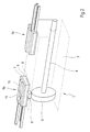
- Figur 1
- eine perspektivische, schematische Darstellung eines Pneumatikzylinders als Linearantrieb, welcher mit einer Einrichtung zur Ermittlung der aktuellen Stellung des innenliegenden Kolbens ausgestattet ist, und
- Figur 2
- eine perspektivische schematische Darstellung eines weiteren Pneumatikzylinders als Linearantrieb, welcher mit einer Einrichtung zur Ermittlung beider Endlagenpositionen eines integrierten Antriebsgliedes ausgestattet ist.
- Gemäß Figur 1 besteht der hier als Pneumatikzylinder 1 ausgebildete Linearantrieb im Wesentlichen aus einem Antriebsgehäuse 2, in welchem ein Antriebsglied 3 in Form eines Kolbens längs bewegbar untergebracht ist. Vom Antriebsglied 3 aus verläuft eine Antriebsstange 4, hier eine Kolbenstange, welche das Antriebsgehäuse 2 zu einer Seite hin abgedichtet durchdringt, um die mit dem Pneumatikzylinder 1 erzeugte mechanische Kraft nach außen hin weiterzugeben. Die Krafterzeugung erfolgt in herkömmlicher Weise über - nicht weiter dargestellte - äußere Druckmittelanschlüsse, mit welchen das innenliegende Antriebsglied 3 wechselseitig beaufschlagbar ist, um ein Ein- oder Ausfahren der Antriebsstange 4 zu bewirken. Die Länge des Pneumatikzylinders 1 definiert den maximal möglichen Hub der Antriebsstange 4.
- Des weiteren sind die Mittel zur Detektion der aktuellen Stellung des Antriebsgliedes 3 vorgesehen, welche über den gesamten Hubbereich des Pneumatikzylinders 1 verlaufen und im Wesentlichen aus einem Potentiometerfolienelement 5 bestehen. Das Potentiometerfolienelement 5 wird von einem im Antriebsglied 3 integrierten Permanentmagneten 6 magnetisch betätigt, indem eine Kontaktelektrode 7 des Potentiometerfolienelements 6 achsparallel zur Bewegungsrichtung des Antriebsglieds 3 verläuft und auf eine unterhalb angeordnete Widerstandsbahn 8 niedergedrückt wird, sobald das nach radial außen gerichtete magnetische Feld des Permanentmagneten 6 eine entsprechend örtlich konzentrierte Zugkraft aufbringt. Wenn sich der Permanentmagnet 6 nicht im Wirkungsbereich des Potentiometerfolienelements 5 befindet, dann bleibt die Kontaktelektrode 7 von der Widerstandsbahn 8 beabstandet. Hierfür dient ein zwischengeordneter Isolierrahmen 9.
- Für weitere Einzelheiten hinsichtlich des Potentiometerfolienelements 5 wird an dieser Stelle voll inhaltlich auf die DE 43 35 004 C2 verwiesen, welche Aufbau und Funktion eines Potentiometerfolienelements der Gattung nach näher beschreibt.
- Zur Verstärkung der magnetischen Kraft, welche die Kontaktelektrode 7 des Potentiometerfolienelements 5 betätigt, ist an der dem Permanentmagneten 6 des Antriebsgliedes 3 gegenüberliegenden Seite des Potentiometerfolienelements 5 ein Verstärkungselement 10 vorgesehen. Das Verstärkungselement 10 ist hier als eine auf einer oberen Betätigungsoberfläche 11 aufgebrachte ferrohaltige Kunststofffolie ausgebildet.
- In der Figur 2 sind spezielle Mittel zur Detektion der beiden Endlagenpositionen vorgesehen, welche nur im Bereich beider Endlagen angeordnet sind und im Wesentlichen aus je einem Potentiometerfolienelement 5a, 5b bestehen. Die Potentiometerfolienelemente 5a und 5b werden auch hier von einem im Antriebsglied 3 integrierten Permanentmagneten 6 magnetisch betätigt. Ansonsten gleicht diese Ausführungsform der vorstehend beschriebenen Ausführungsform.
- Die Erfindung ist nicht beschränkt auf die vorstehend beschriebenen bevorzugten Ausführungsformen. Es sind vielmehr auch eine Reihe von Varianten hiervon denkbar, die vom Schutzbereich der Ansprüche umfasst sind. So ist die Anwendung der erfindungsgemäßen Einrichtung nicht allein beschränkt auf Pneumatikzylinder. Es können hiermit vielmehr auch andere als Linear- oder Drehantriebe ausgebildete Aktoren ausgestattet werden.
-
- 1
- Pneumatikzylinder
- 2
- Antriebsgehäuse
- 3
- Antriebsglied
- 4
- Antriebsstange
- 5
- Potentiometerfolienelement
- 6
- Permanentmagnet
- 7
- Kontaktelektrode
- 8
- Widerstandsbahn
- 9
- Isolierrahmen
- 10
- Verstärkungselement
- 11
- Betätigungsoberfläche
Claims (6)
- Einrichtung zur Ermittlung der aktuellen Stellung eines Antriebsgliedes (3) entlang des Hubwegs oder Drehwinkels, insbesondere bei einem druckmittelbetriebenen Linear- bzw. Drehantrieb, das innerhalb eines Antriebsgehäuses (2) durch Druckmittelbeaufschlagung bewegbar untergebracht ist, wobei das Antriebsglied (3) einen Permanentmagneten (6) zum magnetischen Zusammenwirken mit außerhalb oder am Antriebsgehäuse (2) angeordneten Mitteln zur Detektion der aktuellen Stellung eines Antriebsgliedes (3) aufweist,
dadurch gekennzeichnet, dass die Mittel zur Detektion der aktuellen Stellung ein im magnetischen Wirkbereich des Permanentmagneten (6) und entlang des Hubwegs bzw. Drehwinkels angeordnetes Potentiometerfolienelement (5) umfassen, dessen Kontaktelektrode (7) achsparallel zum Antriebsglied (3) verläuft und über die magnetische Kraft des Permanentmagneten (6) örtlich konzentriert betätigbar ist, wobei an der dem Permanentmagneten (6) des Antriebsgliedes (3) gegenüberliegenden Seite des Potentiometerfolienelements (5) mindestens ein Verstärkungselement (10) in Form eines auf der Betätigungsoberfläche (11) des Potentiometerfolienelements (5) aufgebrachte ferrohaltige Kunststofffolie angeordnet ist. - Einrichtung nach Anspruch 1,
dadurch gekennzeichnet, dass die Mittel zu Detektion der aktuellen Stellung eines Antriebsgliedes (3) lediglich in mindestens einer Endlagenposition desselben angeordnet sind, um eine Art Endlagenschalter zu bilden. - Einrichtung nach Anspruch 1 oder 2,
dadurch gekennzeichnet, dass das Antriebsglied (3) ein Kolben eines Pneumatikzylinders (1) als Linearantrieb ist. - Einrichtung nach Anspruch 1 oder 2,
dadurch gekennzeichnet, dass das Antriebsglied (3) ein Drehflügel eines pneumatischen Drehantriebs ist. - Einrichtung nach Anspruch 2,
dadurch gekennzeichnet, dass der Linearantrieb bzw. der Drehantrieb genau zwei Endlagenpositionen aufweist, denen jeweils ein einziges Potentiometerfolienelement (5a, 5b) zugeordnet ist. - Einrichtung nach einem der vorstehenden Ansprüche,
dadurch gekennzeichnet, dass das Potentiometerfolienelement (5; 5a, 5b) innerhalb eines in die Wandung des Antriebsgehäuses (2) eingebrachten geschlossenen Kanals untergebracht ist.
Applications Claiming Priority (4)
| Application Number | Priority Date | Filing Date | Title |
|---|---|---|---|
| DE10329045 | 2003-06-27 | ||
| DE10329044 | 2003-06-27 | ||
| DE2003129045 DE10329045B4 (de) | 2003-06-27 | 2003-06-27 | Einrichtung zur Ermittlung mindestens einer Endlagenposition eines Antriebsgliedes, insbesondere eines druckmittelbetriebenen Linear- oder Drehantriebes |
| DE2003129044 DE10329044B4 (de) | 2003-06-27 | 2003-06-27 | Einrichtung zur Ermittlung der aktuellen Stellung eines Antriebsgliedes entlang des Hubwegs oder Drehwinkels, insbesondere bei einem druckmittelbetriebenen Linear- bzw. Drehantrieb |
Publications (2)
| Publication Number | Publication Date |
|---|---|
| EP1491771A1 true EP1491771A1 (de) | 2004-12-29 |
| EP1491771B1 EP1491771B1 (de) | 2006-03-01 |
Family
ID=33420024
Family Applications (1)
| Application Number | Title | Priority Date | Filing Date |
|---|---|---|---|
| EP04103012A Expired - Lifetime EP1491771B1 (de) | 2003-06-27 | 2004-06-28 | Einrichtung zur Ermittlung der aktuellen Stellung eines Antriebsgliedes |
Country Status (3)
| Country | Link |
|---|---|
| EP (1) | EP1491771B1 (de) |
| AT (1) | ATE319015T1 (de) |
| DE (1) | DE502004000325D1 (de) |
Cited By (5)
| Publication number | Priority date | Publication date | Assignee | Title |
|---|---|---|---|---|
| WO2008058751A3 (de) * | 2006-11-18 | 2009-01-29 | Hirschmann Automotive Gmbh | Magnetischer positionssensor |
| EP2071276A1 (de) * | 2007-11-23 | 2009-06-17 | Metallux AG | Sensor |
| EP2230486A2 (de) | 2009-03-19 | 2010-09-22 | Metallux AG | Positionssensor |
| DE102009020286A1 (de) | 2009-05-07 | 2010-11-11 | Robert Bosch Gmbh | Kolben mit variablem Permanent-Magneten |
| DE102016213514A1 (de) * | 2016-07-22 | 2018-01-25 | Continental Automotive Gmbh | Passiver magnetischer Positionssensor |
Families Citing this family (2)
| Publication number | Priority date | Publication date | Assignee | Title |
|---|---|---|---|---|
| DE202008013690U1 (de) | 2007-11-26 | 2009-02-12 | Metallux Ag | Sensor |
| DE102009025458B4 (de) | 2009-06-19 | 2016-09-01 | Metallux Ag | Sensor |
Citations (4)
| Publication number | Priority date | Publication date | Assignee | Title |
|---|---|---|---|---|
| US3736396A (en) * | 1970-08-06 | 1973-05-29 | H Siegel | Minimum friction contactors |
| DE3803268A1 (de) * | 1988-02-04 | 1989-04-13 | Bosch Gmbh Robert | Messeinrichtung fuer einen arbeitszylinder |
| DE4335004A1 (de) * | 1993-10-14 | 1995-04-20 | Hoffmann & Krippner Gmbh | Sensor |
| US5442865A (en) * | 1993-03-24 | 1995-08-22 | Vdo Adolf Schindling Ag | Passive magnetic position sensor |
-
2004
- 2004-06-28 DE DE502004000325T patent/DE502004000325D1/de not_active Expired - Lifetime
- 2004-06-28 AT AT04103012T patent/ATE319015T1/de not_active IP Right Cessation
- 2004-06-28 EP EP04103012A patent/EP1491771B1/de not_active Expired - Lifetime
Patent Citations (4)
| Publication number | Priority date | Publication date | Assignee | Title |
|---|---|---|---|---|
| US3736396A (en) * | 1970-08-06 | 1973-05-29 | H Siegel | Minimum friction contactors |
| DE3803268A1 (de) * | 1988-02-04 | 1989-04-13 | Bosch Gmbh Robert | Messeinrichtung fuer einen arbeitszylinder |
| US5442865A (en) * | 1993-03-24 | 1995-08-22 | Vdo Adolf Schindling Ag | Passive magnetic position sensor |
| DE4335004A1 (de) * | 1993-10-14 | 1995-04-20 | Hoffmann & Krippner Gmbh | Sensor |
Cited By (10)
| Publication number | Priority date | Publication date | Assignee | Title |
|---|---|---|---|---|
| WO2008058751A3 (de) * | 2006-11-18 | 2009-01-29 | Hirschmann Automotive Gmbh | Magnetischer positionssensor |
| JP2010510480A (ja) * | 2006-11-18 | 2010-04-02 | ヒルシュマン オートモーティヴ ゲゼルシャフト ミット ベシュレンクテル ハフツング | 磁気式のポジションセンサ |
| US8330450B2 (en) | 2006-11-18 | 2012-12-11 | Hirschmann Automotive Gmbh | Magnetic position sensor |
| EP2071276A1 (de) * | 2007-11-23 | 2009-06-17 | Metallux AG | Sensor |
| EP2230486A2 (de) | 2009-03-19 | 2010-09-22 | Metallux AG | Positionssensor |
| DE102009013533A1 (de) | 2009-03-19 | 2010-09-23 | Metallux Ag | Positionssensor |
| EP2230486A3 (de) * | 2009-03-19 | 2012-08-01 | Metallux AG | Positionssensor |
| DE102009020286A1 (de) | 2009-05-07 | 2010-11-11 | Robert Bosch Gmbh | Kolben mit variablem Permanent-Magneten |
| DE102016213514A1 (de) * | 2016-07-22 | 2018-01-25 | Continental Automotive Gmbh | Passiver magnetischer Positionssensor |
| US11022478B2 (en) | 2016-07-22 | 2021-06-01 | Vitesco Technologies GmbH | Passive magnetic position sensor |
Also Published As
| Publication number | Publication date |
|---|---|
| ATE319015T1 (de) | 2006-03-15 |
| DE502004000325D1 (de) | 2006-04-27 |
| EP1491771B1 (de) | 2006-03-01 |
Similar Documents
| Publication | Publication Date | Title |
|---|---|---|
| EP0427102B1 (de) | Strömungsmesser zur Messung der Durchflussmenge in einer Leitung | |
| EP1489385B1 (de) | Vorrichtung zur Sensierung der axialen Stellung eines ersten Bauteils, das relativ zu einem zweiten Bauteil bewegbar ist | |
| EP1250534B1 (de) | Antrieb eines stellventils mit sensiereinheit zur ventilpositionserfassung | |
| EP1914459A1 (de) | Ventilanordnung mit Positionssensor | |
| EP1491771B1 (de) | Einrichtung zur Ermittlung der aktuellen Stellung eines Antriebsgliedes | |
| DE2553454B2 (de) | Permanentmagnetische Anzeigevorrichtung, vornehmlich für Strömungsmesser | |
| EP0268030B1 (de) | Potentiometer bzw. veränderbarer Widerstand | |
| DE102012219173A1 (de) | Sensorsystem und Kolben-Zylinder-Anordnung, insbesondere zur Verwendung in einem Kupplungsbetätigungssystem in einem Kraftfahrzeug | |
| DE10329044B4 (de) | Einrichtung zur Ermittlung der aktuellen Stellung eines Antriebsgliedes entlang des Hubwegs oder Drehwinkels, insbesondere bei einem druckmittelbetriebenen Linear- bzw. Drehantrieb | |
| DE10152178C2 (de) | Druckmittelzylinder mit einem verschiebbaren Sensor zur Detektion der Kolbenstellung | |
| DE102013105495A1 (de) | Kolbenhubvorrichtung mit Messanordnung | |
| DE4214284A1 (de) | Elektromagnetischer linearmotor | |
| DE102004004100A1 (de) | Positionssensor und entsprechendes Verfahren zum Detektieren der Position eines Rotationskörpers | |
| DE102005029494B4 (de) | Kolben-Zylinder-Anordnung | |
| EP3262311B1 (de) | Aktuator zur betätigung einer reibkupplung | |
| DE10329045A1 (de) | Einrichtung zur Ermittlung mindestens einer Endlagenposition eines Antriebsgliedes, insbesondere eines druckmittelbetriebenen Linear- oder Drehantrieb | |
| DE102016207982B4 (de) | Stellvorrichtung | |
| DE3240351A1 (de) | Druckmittelbetaetigter arbeitszylinder | |
| DE102005005011A1 (de) | Hydraulikzylinder zur Betätigung eines Cabriolet-Verdeckes | |
| DE19846418A1 (de) | Hydraulikventil mit Sensor | |
| DE3939978A1 (de) | Unterdruck-bremskraftverstaerker | |
| EP2878831A1 (de) | Arbeitszylinder | |
| EP0559634A1 (de) | Wegmesseinrichtung | |
| EP0872857A2 (de) | Elektromagnet zur Betätigung des Stellglieds eines Ventils | |
| DE19846182B4 (de) | Abgasrückführungsventil, enthaltend eine Schaltungsanordnung zur Erfassung des Schaltzustandes wenigstens eines pneumatischen Schaltmittels |
Legal Events
| Date | Code | Title | Description |
|---|---|---|---|
| PUAI | Public reference made under article 153(3) epc to a published international application that has entered the european phase |
Free format text: ORIGINAL CODE: 0009012 |
|
| AK | Designated contracting states |
Kind code of ref document: A1 Designated state(s): AT BE BG CH CY CZ DE DK EE ES FI FR GB GR HU IE IT LI LU MC NL PL PT RO SE SI SK TR |
|
| AX | Request for extension of the european patent |
Extension state: AL HR LT LV MK |
|
| 17P | Request for examination filed |
Effective date: 20041201 |
|
| GRAP | Despatch of communication of intention to grant a patent |
Free format text: ORIGINAL CODE: EPIDOSNIGR1 |
|
| AKX | Designation fees paid |
Designated state(s): AT BE BG CH CY CZ DE DK EE ES FI FR GB GR HU IE IT LI LU MC NL PL PT RO SE SI SK TR |
|
| GRAS | Grant fee paid |
Free format text: ORIGINAL CODE: EPIDOSNIGR3 |
|
| GRAA | (expected) grant |
Free format text: ORIGINAL CODE: 0009210 |
|
| AK | Designated contracting states |
Kind code of ref document: B1 Designated state(s): AT BE BG CH CY CZ DE DK EE ES FI FR GB GR HU IE IT LI LU MC NL PL PT RO SE SI SK TR |
|
| PG25 | Lapsed in a contracting state [announced via postgrant information from national office to epo] |
Ref country code: IE Free format text: LAPSE BECAUSE OF FAILURE TO SUBMIT A TRANSLATION OF THE DESCRIPTION OR TO PAY THE FEE WITHIN THE PRESCRIBED TIME-LIMIT Effective date: 20060301 Ref country code: SI Free format text: LAPSE BECAUSE OF FAILURE TO SUBMIT A TRANSLATION OF THE DESCRIPTION OR TO PAY THE FEE WITHIN THE PRESCRIBED TIME-LIMIT Effective date: 20060301 Ref country code: SK Free format text: LAPSE BECAUSE OF FAILURE TO SUBMIT A TRANSLATION OF THE DESCRIPTION OR TO PAY THE FEE WITHIN THE PRESCRIBED TIME-LIMIT Effective date: 20060301 Ref country code: RO Free format text: LAPSE BECAUSE OF FAILURE TO SUBMIT A TRANSLATION OF THE DESCRIPTION OR TO PAY THE FEE WITHIN THE PRESCRIBED TIME-LIMIT Effective date: 20060301 Ref country code: NL Free format text: LAPSE BECAUSE OF FAILURE TO SUBMIT A TRANSLATION OF THE DESCRIPTION OR TO PAY THE FEE WITHIN THE PRESCRIBED TIME-LIMIT Effective date: 20060301 Ref country code: PL Free format text: LAPSE BECAUSE OF FAILURE TO SUBMIT A TRANSLATION OF THE DESCRIPTION OR TO PAY THE FEE WITHIN THE PRESCRIBED TIME-LIMIT Effective date: 20060301 Ref country code: FI Free format text: LAPSE BECAUSE OF FAILURE TO SUBMIT A TRANSLATION OF THE DESCRIPTION OR TO PAY THE FEE WITHIN THE PRESCRIBED TIME-LIMIT Effective date: 20060301 |
|
| REG | Reference to a national code |
Ref country code: GB Ref legal event code: FG4D Free format text: NOT ENGLISH |
|
| REG | Reference to a national code |
Ref country code: CH Ref legal event code: EP |
|
| REG | Reference to a national code |
Ref country code: IE Ref legal event code: FG4D Free format text: LANGUAGE OF EP DOCUMENT: GERMAN |
|
| REF | Corresponds to: |
Ref document number: 502004000325 Country of ref document: DE Date of ref document: 20060427 Kind code of ref document: P |
|
| PG25 | Lapsed in a contracting state [announced via postgrant information from national office to epo] |
Ref country code: DK Free format text: LAPSE BECAUSE OF FAILURE TO SUBMIT A TRANSLATION OF THE DESCRIPTION OR TO PAY THE FEE WITHIN THE PRESCRIBED TIME-LIMIT Effective date: 20060601 Ref country code: BG Free format text: LAPSE BECAUSE OF FAILURE TO SUBMIT A TRANSLATION OF THE DESCRIPTION OR TO PAY THE FEE WITHIN THE PRESCRIBED TIME-LIMIT Effective date: 20060601 |
|
| REG | Reference to a national code |
Ref country code: SE Ref legal event code: TRGR |
|
| PG25 | Lapsed in a contracting state [announced via postgrant information from national office to epo] |
Ref country code: ES Free format text: LAPSE BECAUSE OF FAILURE TO SUBMIT A TRANSLATION OF THE DESCRIPTION OR TO PAY THE FEE WITHIN THE PRESCRIBED TIME-LIMIT Effective date: 20060612 |
|
| GBT | Gb: translation of ep patent filed (gb section 77(6)(a)/1977) |
Effective date: 20060519 |
|
| PG25 | Lapsed in a contracting state [announced via postgrant information from national office to epo] |
Ref country code: MC Free format text: LAPSE BECAUSE OF NON-PAYMENT OF DUE FEES Effective date: 20060630 Ref country code: BE Free format text: LAPSE BECAUSE OF NON-PAYMENT OF DUE FEES Effective date: 20060630 |
|
| PG25 | Lapsed in a contracting state [announced via postgrant information from national office to epo] |
Ref country code: PT Free format text: LAPSE BECAUSE OF FAILURE TO SUBMIT A TRANSLATION OF THE DESCRIPTION OR TO PAY THE FEE WITHIN THE PRESCRIBED TIME-LIMIT Effective date: 20060801 |
|
| NLV1 | Nl: lapsed or annulled due to failure to fulfill the requirements of art. 29p and 29m of the patents act | ||
| REG | Reference to a national code |
Ref country code: IE Ref legal event code: FD4D |
|
| ET | Fr: translation filed | ||
| PLBE | No opposition filed within time limit |
Free format text: ORIGINAL CODE: 0009261 |
|
| STAA | Information on the status of an ep patent application or granted ep patent |
Free format text: STATUS: NO OPPOSITION FILED WITHIN TIME LIMIT |
|
| 26N | No opposition filed |
Effective date: 20061204 |
|
| PG25 | Lapsed in a contracting state [announced via postgrant information from national office to epo] |
Ref country code: AT Free format text: LAPSE BECAUSE OF NON-PAYMENT OF DUE FEES Effective date: 20060628 |
|
| BERE | Be: lapsed |
Owner name: REXROTH MECMAN G.M.B.H. Effective date: 20060630 |
|
| PG25 | Lapsed in a contracting state [announced via postgrant information from national office to epo] |
Ref country code: CZ Free format text: LAPSE BECAUSE OF FAILURE TO SUBMIT A TRANSLATION OF THE DESCRIPTION OR TO PAY THE FEE WITHIN THE PRESCRIBED TIME-LIMIT Effective date: 20060301 Ref country code: GR Free format text: LAPSE BECAUSE OF FAILURE TO SUBMIT A TRANSLATION OF THE DESCRIPTION OR TO PAY THE FEE WITHIN THE PRESCRIBED TIME-LIMIT Effective date: 20060602 |
|
| PG25 | Lapsed in a contracting state [announced via postgrant information from national office to epo] |
Ref country code: EE Free format text: LAPSE BECAUSE OF FAILURE TO SUBMIT A TRANSLATION OF THE DESCRIPTION OR TO PAY THE FEE WITHIN THE PRESCRIBED TIME-LIMIT Effective date: 20060301 |
|
| PG25 | Lapsed in a contracting state [announced via postgrant information from national office to epo] |
Ref country code: TR Free format text: LAPSE BECAUSE OF FAILURE TO SUBMIT A TRANSLATION OF THE DESCRIPTION OR TO PAY THE FEE WITHIN THE PRESCRIBED TIME-LIMIT Effective date: 20060301 Ref country code: LU Free format text: LAPSE BECAUSE OF NON-PAYMENT OF DUE FEES Effective date: 20060628 Ref country code: HU Free format text: LAPSE BECAUSE OF FAILURE TO SUBMIT A TRANSLATION OF THE DESCRIPTION OR TO PAY THE FEE WITHIN THE PRESCRIBED TIME-LIMIT Effective date: 20060902 |
|
| PG25 | Lapsed in a contracting state [announced via postgrant information from national office to epo] |
Ref country code: CY Free format text: LAPSE BECAUSE OF FAILURE TO SUBMIT A TRANSLATION OF THE DESCRIPTION OR TO PAY THE FEE WITHIN THE PRESCRIBED TIME-LIMIT Effective date: 20060301 |
|
| REG | Reference to a national code |
Ref country code: CH Ref legal event code: PL |
|
| PG25 | Lapsed in a contracting state [announced via postgrant information from national office to epo] |
Ref country code: CH Free format text: LAPSE BECAUSE OF NON-PAYMENT OF DUE FEES Effective date: 20080630 Ref country code: LI Free format text: LAPSE BECAUSE OF NON-PAYMENT OF DUE FEES Effective date: 20080630 |
|
| PGFP | Annual fee paid to national office [announced via postgrant information from national office to epo] |
Ref country code: SE Payment date: 20091222 Year of fee payment: 7 |
|
| PGFP | Annual fee paid to national office [announced via postgrant information from national office to epo] |
Ref country code: FR Payment date: 20100706 Year of fee payment: 7 |
|
| PGFP | Annual fee paid to national office [announced via postgrant information from national office to epo] |
Ref country code: IT Payment date: 20100626 Year of fee payment: 7 |
|
| PGFP | Annual fee paid to national office [announced via postgrant information from national office to epo] |
Ref country code: DE Payment date: 20100824 Year of fee payment: 7 Ref country code: GB Payment date: 20100401 Year of fee payment: 7 |
|
| REG | Reference to a national code |
Ref country code: SE Ref legal event code: EUG |
|
| GBPC | Gb: european patent ceased through non-payment of renewal fee |
Effective date: 20110628 |
|
| PG25 | Lapsed in a contracting state [announced via postgrant information from national office to epo] |
Ref country code: IT Free format text: LAPSE BECAUSE OF NON-PAYMENT OF DUE FEES Effective date: 20110628 |
|
| REG | Reference to a national code |
Ref country code: FR Ref legal event code: ST Effective date: 20120229 |
|
| REG | Reference to a national code |
Ref country code: DE Ref legal event code: R119 Ref document number: 502004000325 Country of ref document: DE Effective date: 20120103 |
|
| PG25 | Lapsed in a contracting state [announced via postgrant information from national office to epo] |
Ref country code: FR Free format text: LAPSE BECAUSE OF NON-PAYMENT OF DUE FEES Effective date: 20110630 Ref country code: DE Free format text: LAPSE BECAUSE OF NON-PAYMENT OF DUE FEES Effective date: 20120103 |
|
| PG25 | Lapsed in a contracting state [announced via postgrant information from national office to epo] |
Ref country code: GB Free format text: LAPSE BECAUSE OF NON-PAYMENT OF DUE FEES Effective date: 20110628 |
|
| PG25 | Lapsed in a contracting state [announced via postgrant information from national office to epo] |
Ref country code: SE Free format text: LAPSE BECAUSE OF NON-PAYMENT OF DUE FEES Effective date: 20110629 |