EP1495718A1 - Appareil d'imagerie par résonance magnétique - Google Patents
Appareil d'imagerie par résonance magnétique Download PDFInfo
- Publication number
- EP1495718A1 EP1495718A1 EP04101741A EP04101741A EP1495718A1 EP 1495718 A1 EP1495718 A1 EP 1495718A1 EP 04101741 A EP04101741 A EP 04101741A EP 04101741 A EP04101741 A EP 04101741A EP 1495718 A1 EP1495718 A1 EP 1495718A1
- Authority
- EP
- European Patent Office
- Prior art keywords
- scanner
- patient support
- mri
- magnetic resonance
- resonance imaging
- Prior art date
- Legal status (The legal status is an assumption and is not a legal conclusion. Google has not performed a legal analysis and makes no representation as to the accuracy of the status listed.)
- Granted
Links
Images


Classifications
-
- A—HUMAN NECESSITIES
- A61—MEDICAL OR VETERINARY SCIENCE; HYGIENE
- A61B—DIAGNOSIS; SURGERY; IDENTIFICATION
- A61B5/00—Measuring for diagnostic purposes; Identification of persons
- A61B5/05—Detecting, measuring or recording for diagnosis by means of electric currents or magnetic fields; Measuring using microwaves or radio waves
- A61B5/055—Detecting, measuring or recording for diagnosis by means of electric currents or magnetic fields; Measuring using microwaves or radio waves involving electronic [EMR] or nuclear [NMR] magnetic resonance, e.g. magnetic resonance imaging
-
- A—HUMAN NECESSITIES
- A61—MEDICAL OR VETERINARY SCIENCE; HYGIENE
- A61B—DIAGNOSIS; SURGERY; IDENTIFICATION
- A61B5/00—Measuring for diagnostic purposes; Identification of persons
- A61B5/70—Means for positioning the patient in relation to the detecting, measuring or recording means
- A61B5/704—Tables
Definitions
- the invention relates to an apparatus for MRI (Magnetic Resonance Imaging) including a scanner, a support for the patient, and supporting benches for supporting the scanner and the patient.
- MRI Magnetic Resonance Imaging
- Magnetic Resonance Imaging apparatus comprising means for supporting the patient in different ways, and having one or more degrees of freedom with respect to the scanner. It is also well known from prior art to use means for supporting and moving the scanner itself with respect to the room where the examination takes place and with respect to the patient himself.
- Prior art apparatus have some problems as regards the correct positioning of the patient: the patient often has to take unnatural positions during the examination in order to examine a particular part of his body, and he needs to be repositioned to scan the different body parts in the correct way.
- the examination needs a frequent and time-wasting initial phase of positioning, since the medical staff has to set the position of the scanner and the patient support in such a way to obtain the best results in imaging the part of the patient body under examination.
- the object of the invention is to provide an MRI apparatus that ia able to overcome said disadvantages above mentioned.
- the lines from the scanner to/from the patient support are located inside the bench itself, this causes less problems when installing or moving the MRI apparatus from/to another room, in fact the above mentioned lines are internal to the bench, being not necessary to locate them under the floor or the walls.
- the apparatus according to the present invention has an height from ground substantially equal to the height of patient support from ground minus the thickness of the patient support itself, and this is an important advantage, because the substantially rounded external shape of the bench, in combination with its height leads to a kind of bench that is not particularly wide, but at the same time it is sufficient for containing all the means for moving and positioning the scanner and the patient support.
- the supporting bench of the present invention allows the patient to stand still during the examination, since the internal part of the scanner examination cavity where the patient uses to lay his body part under examination is substantially as the same height of the patient himself, in such a way that the patient stands in an examination position and he is not under physical stress and he can stand still during the examination process.
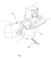
- the first embodiment of fig.1 relates to a particular bench 3 according to the present invention wherein the external shape of the bench 3 itself is a substantially rounded shape, moreover in this embodiment the bench 3 has an overview T-shape: the scanner 1 is mounted over the elongated part of the T-shaped bench 3 while the patient support 2 is mounted on a different part of the bench which is perpendicular to the elongated part in such a way to form an overview T-shape.
- the bench 103 of the patient support 2 is mounted on a guide 204 which allows it to move along said guide 204.
- the scanner 1 is mounted on a scanner guide 104 which, in this particular embodiment, is perpendicular to the patient support guide 204, and said scanner guide 104 is mounted on the top and along the longitudinal extension of the bench 3.
- known guides 4 for rotation/translation are provided in order to achieve the possible motions of figs. 2, 3 and 4, which guides are positioned between the patient support 2 and the patient support bench 103 and between the scanner 1 and the scanner guide 104 and between the patient support bench 103 and the patient support guide 204.
- the scanner 1 in this figure the scanner 1 is positioned in the middle of the bench 104 and stands in front of the patient support 2, allowing the patient to introduce in the scanner cavity his lower part of the body.
- the bench 3 has an height from ground substantially equal to the height of the patient support 2 from ground minus the thickness of the patient support 2 itself, and/or an height from ground substantially equal to the height of patient support 2 from ground minus the thickness of the lower part of the scanner examination cavity. This is a great advantage, in fact such height is useful in order to position the patient under examination in a comfortable way, allowing the patient to rest during the examination in a steady position, leading to a better and shorter imaging process.
- the total height of the patient support bench 103 corresponds to the height of the bench 3, and it is possible to remove the patient support guide 204, having a T-shaped fixed bench, where the patient support bench 103 is simply a perpendicular extension of the main bench 3.
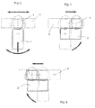
- the positioning illustrated in figs. 2, 3 and 4 are only examples of the possible positioning between the bench 3 and the patient support 2; moreover the positioning may be manual or may be driven by electric/electronic devices not shown in figures, being known art.
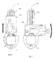
- fig. 5 is illustrated another preferred embodiment of the invention, wherein the bench 3 has only a longitudinal extension, but having a particular cross section.
- the scanner 1 is secured at one end of the bench 3 in side position with respect to the longitudinal extension of the bench 3 itself, while the patient support 2 can rotate and/or translate along the bench 3 in order to introduce the patient part under examination inside the examination cavity of the scanner.
- the patient support 2 may translate and rotate along the bench 3 in the direction illustrated by black arrows. This leads to a short examination apparatus in which the T-shape figured out in fig. 1 is not necessary, and in which the scanner 1 itself is fixed.
- the advantages are that the whole space that has been used is even less than the space used in the apparatus shown in fig. 1, and the electric/electronic driving for the positioning is easier.
- the height of the bench is optimal for positioning the patient on the patient support, in fact the height of patient support is the normal sitting height for a person, this leading to a comfortable movements for the patient, moreover, by using the bench 3 according to the invention, the heights of the scanner 1 and the patient support 2 with respect with each other, allow the patient body parts under examination to lay in a comfortably position for the patient itself.
- figs.6 and 7 are shown the different positioning for leg/foot examination and arm/shoulder examination respectively, obtained by the rotation/translation of the patient support 2 along the patient support guide 204 positioned on the top of the bench 3, as shown also in fig. 5.
- the bench 3 has a particular symmetrical cross section, shown in fig. 8. this cross section shows a central arched part ending on both sides with two supporting wings 203 forming each one a lateral groove. Each wing starts from the ending lateral edge of the arched part and has a planar surface in this preferred embodiments, the arched part ends at his center at an upper level with respect to the two wings.
- the patient support guide 204 is positioned at the top of the bench 3 and it will be noted also the particular supporting wings 203 of this particular bench 3; this supporting wings 203 may be very useful in case of heavy patients and in all that cases when it is necessary to have a strong and well fixed structure for the patient support.
- the patient support itself is represented by a seat with a movable back, being possible to use also a table, and being possible also to use a movable scanner 1 as shown in figs. 1, 2, 3, 4.
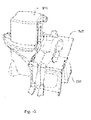
- the bench 3 has a external rounded shape, as shown and disclosed for figs. 1, 2, 3, 4, but in fig. 9 the overview shape of the bench 3 itself has only a longitudinal extension, as shown and disclosed for figs. 5, 6, 7, 8.
- the scanner 1 may translate along the bench 3 by using a scanner guide 104, while the patient support 2 is secured at one end of the bench 3 and may only rotate about its vertical axis.
- the supporting bench 3 has a rounded cross section, as said above, since the scanner is often less heavy than the patient support with the patient himself, and there is no need of a supporting shapein order to have a well fixed structure. This leads to a less expensive apparatus but also a less strong apparatus than the one shown in figs. 5, 6, 7, and 8.
- figs. 10 and 11 are illustrated the examination positions for arm/shoulder and leg/foot respectively.
- the scanner 1 may translate along the scanner guide 104 as shown by black arrows, and the guide 104 is positioned as usual at the top of the bench 3.
- the scanner has only means for translating along the bench, while the patient support may rotate only with respect to its vertical axis as shown by black arrows on the top of the drawings.
- the means for rotating the patient support 2 is only a rotational guide positioned under the patient support 2 itself and over the bench 3. From a comparision between fig. 6 and fig. 11 it is evident that the embodiment of fig. 6 takes less space than the embodiment of fig.
- the supporting bench 3 of fig. 9 achieves all the advantages disclosed for the supporting bench of figs. 1 and 5 and related to the comfortable positioning of the patient and of the part of the patient under examination.
- the fourth preferred embodiment is illustrated in fig. 12.
- the supporting bench 3 has a longitudinal extension substantially equal to the length of the scanner 1 plus the width of the patient support 2, while the supporting bench 3 has the same height as disclosed above, achieving the same advantages for the patient comfortable positioning related matter.
- the patient support 2 can rotate along a guide while the scanner can rotate about its vertical axis in order to introduce the patient part under examination in the examination cavity of the scanner.
- figs. 13, 14, 15 that the scanner 1 and the patient support 2 work together in order to achieve the right position.
- fig. 13 is shown the position for leg/foot examination
- in fig. 14 is shown the position for left arm/shoulder examination
- in fig. 15 is shown the position for right arm/shoulder examination.
- the present embodiment reduces a lot the space used to position the patient under examination in the examination room. This embodiment achieves the same advantages disclosed before for figs .1 to 11.
- the supporting bench 3 may have an internal volume that can be used to locate all or at least part of the electric/electronic driving control and/or the electric/electronic apparatus for processing and generating images, this leading to a space saving, that may be useful when the examination room is a small one.
Landscapes
- Health & Medical Sciences (AREA)
- Life Sciences & Earth Sciences (AREA)
- Physics & Mathematics (AREA)
- Surgery (AREA)
- General Health & Medical Sciences (AREA)
- Engineering & Computer Science (AREA)
- Biomedical Technology (AREA)
- Heart & Thoracic Surgery (AREA)
- Medical Informatics (AREA)
- Molecular Biology (AREA)
- Biophysics (AREA)
- Animal Behavior & Ethology (AREA)
- Pathology (AREA)
- Public Health (AREA)
- Veterinary Medicine (AREA)
- Nuclear Medicine, Radiotherapy & Molecular Imaging (AREA)
- High Energy & Nuclear Physics (AREA)
- Radiology & Medical Imaging (AREA)
- Magnetic Resonance Imaging Apparatus (AREA)
- Surgical Instruments (AREA)
Applications Claiming Priority (2)
| Application Number | Priority Date | Filing Date | Title |
|---|---|---|---|
| US48624003P | 2003-07-11 | 2003-07-11 | |
| US486240P | 2003-07-11 |
Publications (2)
| Publication Number | Publication Date |
|---|---|
| EP1495718A1 true EP1495718A1 (fr) | 2005-01-12 |
| EP1495718B1 EP1495718B1 (fr) | 2006-06-14 |
Family
ID=33452509
Family Applications (1)
| Application Number | Title | Priority Date | Filing Date |
|---|---|---|---|
| EP04101741A Expired - Lifetime EP1495718B1 (fr) | 2003-07-11 | 2004-04-26 | Appareil d'imagerie par résonance magnétique |
Country Status (5)
| Country | Link |
|---|---|
| US (1) | US7725158B2 (fr) |
| EP (1) | EP1495718B1 (fr) |
| AT (1) | ATE329527T1 (fr) |
| DE (1) | DE602004001175T2 (fr) |
| ES (1) | ES2265619T3 (fr) |
Families Citing this family (13)
| Publication number | Priority date | Publication date | Assignee | Title |
|---|---|---|---|---|
| JP2009540882A (ja) | 2006-06-20 | 2009-11-26 | イムリス インコーポレイテッド | 診察及び外科イメージング用の回転式統合型スキャナー |
| US8144000B2 (en) * | 2007-09-26 | 2012-03-27 | Trimble Navigation Limited | Collision avoidance |
| US8081108B2 (en) * | 2008-01-07 | 2011-12-20 | Trimble Navigation Limited | Autonomous projection of global navigation satellite orbits |
| US7737887B2 (en) | 2008-01-14 | 2010-06-15 | Trimble Navigation Limited | Nudged broadcast orbit drift correction |
| US8264404B2 (en) * | 2008-01-14 | 2012-09-11 | Trimble Navigation Limited | Double-nudged broadcast orbit drift correction |
| US7737888B2 (en) | 2008-01-14 | 2010-06-15 | Trimble Navigation Limited | Conveying orbit information via ambiguous position information |
| US7898409B2 (en) * | 2008-04-09 | 2011-03-01 | Trimble Navigation Limited | Circuit for exclusion zone compliance |
| US8054181B2 (en) * | 2008-04-09 | 2011-11-08 | Trimble Navigation Limited | Terrestial-signal based exclusion zone compliance |
| US8224518B2 (en) * | 2008-08-18 | 2012-07-17 | Trimble Navigation Limited | Automated recordation of crane inspection activity |
| US8514058B2 (en) * | 2008-08-18 | 2013-08-20 | Trimble Navigation Limited | Construction equipment component location tracking |
| US20100070179A1 (en) * | 2008-09-17 | 2010-03-18 | Cameron John F | Providing an autonomous position of a point of interest to a lifting device to avoid collision |
| CN103549957A (zh) * | 2013-11-14 | 2014-02-05 | 江苏麦格思频仪器有限公司 | 核磁共振成像系统及其使用方法 |
| US20240206816A1 (en) * | 2021-04-28 | 2024-06-27 | The United States Government As Represented By The Department Of Veterans Affairs | Device for supporting a patient in connection with medical procedure |
Citations (5)
| Publication number | Priority date | Publication date | Assignee | Title |
|---|---|---|---|---|
| US4875485A (en) * | 1985-11-18 | 1989-10-24 | Kabushiki Kaisha Toshiba | Magnetic resonance system |
| US5779637A (en) * | 1995-05-11 | 1998-07-14 | Elscint, Ltd. | Magnetic resonance imaging system including an image acquisition apparatus rotator |
| EP0927889A2 (fr) * | 1998-01-02 | 1999-07-07 | General Electric Company | Aimant ajustable pour l'imagerie résonance magnétique au cours d'interventions médicales |
| EP1027862A1 (fr) * | 1999-02-10 | 2000-08-16 | PARAMED S.r.l. | Dispositif pour un tomographe à résonance magnétique nucléaire |
| DE19923947A1 (de) * | 1999-05-25 | 2000-12-07 | Siemens Ag | Magnetresonanztomographiegerät, insbesondere für den interoperativen Einsatz |
Family Cites Families (6)
| Publication number | Priority date | Publication date | Assignee | Title |
|---|---|---|---|---|
| US4964793A (en) * | 1988-03-28 | 1990-10-23 | Antosh Mark J | Solar induction monorail fabrication apparatus |
| DE59506450D1 (de) * | 1994-05-11 | 1999-09-02 | Voelker Moebelproduktionsgesel | Bett, insbesondere Krankenbett |
| IT1298015B1 (it) * | 1997-09-16 | 1999-12-20 | Esaote Spa | Lettino in particolare nelle macchine per il rilevamento d'immagine in risonanza magnetica nucleare. |
| US6456684B1 (en) * | 1999-07-23 | 2002-09-24 | Inki Mun | Surgical scanning system and process for use thereof |
| JP4093736B2 (ja) * | 2001-06-28 | 2008-06-04 | 株式会社日立メディコ | 核磁気共鳴診断装置および診断システム |
| US6973689B2 (en) * | 2001-11-14 | 2005-12-13 | Koninklijke Philips Electronics N.V. | Docking means for medical system comprising examination device and patient support device |
-
2004
- 2004-04-26 ES ES04101741T patent/ES2265619T3/es not_active Expired - Lifetime
- 2004-04-26 EP EP04101741A patent/EP1495718B1/fr not_active Expired - Lifetime
- 2004-04-26 AT AT04101741T patent/ATE329527T1/de not_active IP Right Cessation
- 2004-04-26 DE DE602004001175T patent/DE602004001175T2/de not_active Expired - Lifetime
- 2004-07-09 US US10/886,695 patent/US7725158B2/en not_active Expired - Lifetime
Patent Citations (5)
| Publication number | Priority date | Publication date | Assignee | Title |
|---|---|---|---|---|
| US4875485A (en) * | 1985-11-18 | 1989-10-24 | Kabushiki Kaisha Toshiba | Magnetic resonance system |
| US5779637A (en) * | 1995-05-11 | 1998-07-14 | Elscint, Ltd. | Magnetic resonance imaging system including an image acquisition apparatus rotator |
| EP0927889A2 (fr) * | 1998-01-02 | 1999-07-07 | General Electric Company | Aimant ajustable pour l'imagerie résonance magnétique au cours d'interventions médicales |
| EP1027862A1 (fr) * | 1999-02-10 | 2000-08-16 | PARAMED S.r.l. | Dispositif pour un tomographe à résonance magnétique nucléaire |
| DE19923947A1 (de) * | 1999-05-25 | 2000-12-07 | Siemens Ag | Magnetresonanztomographiegerät, insbesondere für den interoperativen Einsatz |
Also Published As
| Publication number | Publication date |
|---|---|
| DE602004001175T2 (de) | 2006-12-28 |
| EP1495718B1 (fr) | 2006-06-14 |
| US20050033155A1 (en) | 2005-02-10 |
| ATE329527T1 (de) | 2006-07-15 |
| DE602004001175D1 (de) | 2006-07-27 |
| US7725158B2 (en) | 2010-05-25 |
| ES2265619T3 (es) | 2007-02-16 |
Similar Documents
| Publication | Publication Date | Title |
|---|---|---|
| EP1495718B1 (fr) | Appareil d'imagerie par résonance magnétique | |
| US6385481B2 (en) | Diagnostic system with a chair and table movable on rails provided on vertical magnets thereof | |
| US7196519B2 (en) | Stand-up vertical field MRI apparatus | |
| US5590429A (en) | Electrophysiology table | |
| US6854140B2 (en) | Medical examination/treatment system with multiple patient beds, and transport carriage therefor | |
| US8761861B2 (en) | Magnetic resonance imaging method including coordinated rotation of patient table and magnetic structure | |
| US20020104163A1 (en) | Support device for an imaging medical examination apparatus and method for the operation thereof | |
| US7874031B2 (en) | Patient positioning apparatus for a magnetic resonance device | |
| US10959687B2 (en) | Imaging table-to-head frame adapter | |
| US20020013524A1 (en) | Mri vertical magnet apparatus and mri apparatus | |
| US20100049045A1 (en) | Ultrasonic diagnostic apparatus | |
| JP2006528013A (ja) | 治療用バース | |
| CN110200630B (zh) | 用于磁共振成像的线圈支架及磁共振成像设备 | |
| JP2006507095A (ja) | Mriデュアルスキャニングのための方法、装置、及び施設 | |
| CN202151379U (zh) | 外科升降系统 | |
| US8869327B2 (en) | Patient support apparatus and medical imaging apparatus having the patient support apparatus | |
| JP2009201832A (ja) | 医療用カート | |
| CN212522014U (zh) | 一种胸外科设备固定操作架 | |
| EP3558130B1 (fr) | Appareil d'imagerie dentaire avec agencement de siège mobile intégré | |
| US20070287908A1 (en) | Medical Imaging System | |
| US12070301B1 (en) | Visualization of spinal abnormality using upright MR imaging during spinal treatment | |
| CN223350221U (zh) | 一种cbct诊断床 | |
| US20250352146A1 (en) | Medical Imaging Apparatus with a Patient Support Apparatus | |
| CN112220473A (zh) | 一种基于心电门控技术的mr成像设备 | |
| CN117017335B (zh) | 一种基于全身扫描的床高自动调整系统及方法 |
Legal Events
| Date | Code | Title | Description |
|---|---|---|---|
| PUAI | Public reference made under article 153(3) epc to a published international application that has entered the european phase |
Free format text: ORIGINAL CODE: 0009012 |
|
| AK | Designated contracting states |
Kind code of ref document: A1 Designated state(s): AT BE BG CH CY CZ DE DK EE ES FI FR GB GR HU IE IT LI LU MC NL PL PT RO SE SI SK TR |
|
| AX | Request for extension of the european patent |
Extension state: AL HR LT LV MK |
|
| 17P | Request for examination filed |
Effective date: 20050616 |
|
| AKX | Designation fees paid |
Designated state(s): AT BE BG CH CY CZ DE DK EE ES FI FR GB GR HU IE IT LI LU MC NL PL PT RO SE SI SK TR |
|
| GRAP | Despatch of communication of intention to grant a patent |
Free format text: ORIGINAL CODE: EPIDOSNIGR1 |
|
| RAP1 | Party data changed (applicant data changed or rights of an application transferred) |
Owner name: ESAOTE S.P.A. |
|
| GRAS | Grant fee paid |
Free format text: ORIGINAL CODE: EPIDOSNIGR3 |
|
| GRAA | (expected) grant |
Free format text: ORIGINAL CODE: 0009210 |
|
| RAP1 | Party data changed (applicant data changed or rights of an application transferred) |
Owner name: ESAOTE S.P.A. |
|
| RIN1 | Information on inventor provided before grant (corrected) |
Inventor name: CONTRADA, ORFEO Inventor name: REZZONICO, FABIO |
|
| AK | Designated contracting states |
Kind code of ref document: B1 Designated state(s): AT BE BG CH CY CZ DE DK EE ES FI FR GB GR HU IE IT LI LU MC NL PL PT RO SE SI SK TR |
|
| PG25 | Lapsed in a contracting state [announced via postgrant information from national office to epo] |
Ref country code: SI Free format text: LAPSE BECAUSE OF FAILURE TO SUBMIT A TRANSLATION OF THE DESCRIPTION OR TO PAY THE FEE WITHIN THE PRESCRIBED TIME-LIMIT Effective date: 20060614 Ref country code: IT Free format text: LAPSE BECAUSE OF FAILURE TO SUBMIT A TRANSLATION OF THE DESCRIPTION OR TO PAY THE FEE WITHIN THE PRESCRIBED TIME-LIMIT;WARNING: LAPSES OF ITALIAN PATENTS WITH EFFECTIVE DATE BEFORE 2007 MAY HAVE OCCURRED AT ANY TIME BEFORE 2007. THE CORRECT EFFECTIVE DATE MAY BE DIFFERENT FROM THE ONE RECORDED. Effective date: 20060614 Ref country code: LI Free format text: LAPSE BECAUSE OF FAILURE TO SUBMIT A TRANSLATION OF THE DESCRIPTION OR TO PAY THE FEE WITHIN THE PRESCRIBED TIME-LIMIT Effective date: 20060614 Ref country code: FI Free format text: LAPSE BECAUSE OF FAILURE TO SUBMIT A TRANSLATION OF THE DESCRIPTION OR TO PAY THE FEE WITHIN THE PRESCRIBED TIME-LIMIT Effective date: 20060614 Ref country code: CZ Free format text: LAPSE BECAUSE OF FAILURE TO SUBMIT A TRANSLATION OF THE DESCRIPTION OR TO PAY THE FEE WITHIN THE PRESCRIBED TIME-LIMIT Effective date: 20060614 Ref country code: PL Free format text: LAPSE BECAUSE OF FAILURE TO SUBMIT A TRANSLATION OF THE DESCRIPTION OR TO PAY THE FEE WITHIN THE PRESCRIBED TIME-LIMIT Effective date: 20060614 Ref country code: CH Free format text: LAPSE BECAUSE OF FAILURE TO SUBMIT A TRANSLATION OF THE DESCRIPTION OR TO PAY THE FEE WITHIN THE PRESCRIBED TIME-LIMIT Effective date: 20060614 Ref country code: RO Free format text: LAPSE BECAUSE OF FAILURE TO SUBMIT A TRANSLATION OF THE DESCRIPTION OR TO PAY THE FEE WITHIN THE PRESCRIBED TIME-LIMIT Effective date: 20060614 Ref country code: AT Free format text: LAPSE BECAUSE OF FAILURE TO SUBMIT A TRANSLATION OF THE DESCRIPTION OR TO PAY THE FEE WITHIN THE PRESCRIBED TIME-LIMIT Effective date: 20060614 Ref country code: BE Free format text: LAPSE BECAUSE OF FAILURE TO SUBMIT A TRANSLATION OF THE DESCRIPTION OR TO PAY THE FEE WITHIN THE PRESCRIBED TIME-LIMIT Effective date: 20060614 Ref country code: SK Free format text: LAPSE BECAUSE OF FAILURE TO SUBMIT A TRANSLATION OF THE DESCRIPTION OR TO PAY THE FEE WITHIN THE PRESCRIBED TIME-LIMIT Effective date: 20060614 Ref country code: NL Free format text: LAPSE BECAUSE OF FAILURE TO SUBMIT A TRANSLATION OF THE DESCRIPTION OR TO PAY THE FEE WITHIN THE PRESCRIBED TIME-LIMIT Effective date: 20060614 |
|
| REG | Reference to a national code |
Ref country code: GB Ref legal event code: FG4D |
|
| REG | Reference to a national code |
Ref country code: CH Ref legal event code: EP |
|
| REG | Reference to a national code |
Ref country code: IE Ref legal event code: FG4D |
|
| REF | Corresponds to: |
Ref document number: 602004001175 Country of ref document: DE Date of ref document: 20060727 Kind code of ref document: P |
|
| RAP2 | Party data changed (patent owner data changed or rights of a patent transferred) |
Owner name: ESAOTE S.P.A. |
|
| PG25 | Lapsed in a contracting state [announced via postgrant information from national office to epo] |
Ref country code: DK Free format text: LAPSE BECAUSE OF FAILURE TO SUBMIT A TRANSLATION OF THE DESCRIPTION OR TO PAY THE FEE WITHIN THE PRESCRIBED TIME-LIMIT Effective date: 20060914 Ref country code: SE Free format text: LAPSE BECAUSE OF FAILURE TO SUBMIT A TRANSLATION OF THE DESCRIPTION OR TO PAY THE FEE WITHIN THE PRESCRIBED TIME-LIMIT Effective date: 20060914 |
|
| NLT2 | Nl: modifications (of names), taken from the european patent patent bulletin |
Owner name: ESAOTE S.P.A. Effective date: 20060816 |
|
| PG25 | Lapsed in a contracting state [announced via postgrant information from national office to epo] |
Ref country code: PT Free format text: LAPSE BECAUSE OF FAILURE TO SUBMIT A TRANSLATION OF THE DESCRIPTION OR TO PAY THE FEE WITHIN THE PRESCRIBED TIME-LIMIT Effective date: 20061114 |
|
| NLV1 | Nl: lapsed or annulled due to failure to fulfill the requirements of art. 29p and 29m of the patents act | ||
| REG | Reference to a national code |
Ref country code: CH Ref legal event code: PL |
|
| ET | Fr: translation filed | ||
| REG | Reference to a national code |
Ref country code: ES Ref legal event code: FG2A Ref document number: 2265619 Country of ref document: ES Kind code of ref document: T3 |
|
| PLBE | No opposition filed within time limit |
Free format text: ORIGINAL CODE: 0009261 |
|
| STAA | Information on the status of an ep patent application or granted ep patent |
Free format text: STATUS: NO OPPOSITION FILED WITHIN TIME LIMIT |
|
| 26N | No opposition filed |
Effective date: 20070315 |
|
| PG25 | Lapsed in a contracting state [announced via postgrant information from national office to epo] |
Ref country code: GR Free format text: LAPSE BECAUSE OF FAILURE TO SUBMIT A TRANSLATION OF THE DESCRIPTION OR TO PAY THE FEE WITHIN THE PRESCRIBED TIME-LIMIT Effective date: 20060915 |
|
| PG25 | Lapsed in a contracting state [announced via postgrant information from national office to epo] |
Ref country code: IE Free format text: LAPSE BECAUSE OF NON-PAYMENT OF DUE FEES Effective date: 20070426 |
|
| PG25 | Lapsed in a contracting state [announced via postgrant information from national office to epo] |
Ref country code: BG Free format text: LAPSE BECAUSE OF FAILURE TO SUBMIT A TRANSLATION OF THE DESCRIPTION OR TO PAY THE FEE WITHIN THE PRESCRIBED TIME-LIMIT Effective date: 20060914 |
|
| PG25 | Lapsed in a contracting state [announced via postgrant information from national office to epo] |
Ref country code: EE Free format text: LAPSE BECAUSE OF FAILURE TO SUBMIT A TRANSLATION OF THE DESCRIPTION OR TO PAY THE FEE WITHIN THE PRESCRIBED TIME-LIMIT Effective date: 20060614 |
|
| PGRI | Patent reinstated in contracting state [announced from national office to epo] |
Ref country code: IT Effective date: 20080601 |
|
| PG25 | Lapsed in a contracting state [announced via postgrant information from national office to epo] |
Ref country code: MC Free format text: LAPSE BECAUSE OF NON-PAYMENT OF DUE FEES Effective date: 20070430 |
|
| PG25 | Lapsed in a contracting state [announced via postgrant information from national office to epo] |
Ref country code: CY Free format text: LAPSE BECAUSE OF FAILURE TO SUBMIT A TRANSLATION OF THE DESCRIPTION OR TO PAY THE FEE WITHIN THE PRESCRIBED TIME-LIMIT Effective date: 20060614 Ref country code: LU Free format text: LAPSE BECAUSE OF NON-PAYMENT OF DUE FEES Effective date: 20070426 |
|
| PG25 | Lapsed in a contracting state [announced via postgrant information from national office to epo] |
Ref country code: HU Free format text: LAPSE BECAUSE OF FAILURE TO SUBMIT A TRANSLATION OF THE DESCRIPTION OR TO PAY THE FEE WITHIN THE PRESCRIBED TIME-LIMIT Effective date: 20061215 Ref country code: TR Free format text: LAPSE BECAUSE OF FAILURE TO SUBMIT A TRANSLATION OF THE DESCRIPTION OR TO PAY THE FEE WITHIN THE PRESCRIBED TIME-LIMIT Effective date: 20060614 |
|
| PGFP | Annual fee paid to national office [announced via postgrant information from national office to epo] |
Ref country code: FR Payment date: 20100419 Year of fee payment: 7 |
|
| PGFP | Annual fee paid to national office [announced via postgrant information from national office to epo] |
Ref country code: ES Payment date: 20100630 Year of fee payment: 7 |
|
| PGFP | Annual fee paid to national office [announced via postgrant information from national office to epo] |
Ref country code: GB Payment date: 20100415 Year of fee payment: 7 |
|
| GBPC | Gb: european patent ceased through non-payment of renewal fee |
Effective date: 20110426 |
|
| REG | Reference to a national code |
Ref country code: FR Ref legal event code: ST Effective date: 20111230 |
|
| PG25 | Lapsed in a contracting state [announced via postgrant information from national office to epo] |
Ref country code: FR Free format text: LAPSE BECAUSE OF NON-PAYMENT OF DUE FEES Effective date: 20110502 |
|
| PG25 | Lapsed in a contracting state [announced via postgrant information from national office to epo] |
Ref country code: GB Free format text: LAPSE BECAUSE OF NON-PAYMENT OF DUE FEES Effective date: 20110426 |
|
| REG | Reference to a national code |
Ref country code: ES Ref legal event code: FD2A Effective date: 20120604 |
|
| PG25 | Lapsed in a contracting state [announced via postgrant information from national office to epo] |
Ref country code: ES Free format text: LAPSE BECAUSE OF NON-PAYMENT OF DUE FEES Effective date: 20110427 |
|
| PGFP | Annual fee paid to national office [announced via postgrant information from national office to epo] |
Ref country code: DE Payment date: 20120321 Year of fee payment: 9 |
|
| PG25 | Lapsed in a contracting state [announced via postgrant information from national office to epo] |
Ref country code: DE Free format text: LAPSE BECAUSE OF NON-PAYMENT OF DUE FEES Effective date: 20131101 |
|
| REG | Reference to a national code |
Ref country code: DE Ref legal event code: R119 Ref document number: 602004001175 Country of ref document: DE Effective date: 20131101 |
|
| P01 | Opt-out of the competence of the unified patent court (upc) registered |
Effective date: 20230426 |
|
| PGFP | Annual fee paid to national office [announced via postgrant information from national office to epo] |
Ref country code: IT Payment date: 20230404 Year of fee payment: 20 |