EP1496596A1 - Stator of rotating electric motor - Google Patents
Stator of rotating electric motor Download PDFInfo
- Publication number
- EP1496596A1 EP1496596A1 EP02710379A EP02710379A EP1496596A1 EP 1496596 A1 EP1496596 A1 EP 1496596A1 EP 02710379 A EP02710379 A EP 02710379A EP 02710379 A EP02710379 A EP 02710379A EP 1496596 A1 EP1496596 A1 EP 1496596A1
- Authority
- EP
- European Patent Office
- Prior art keywords
- portions
- stator
- pole tooth
- tooth portion
- frame members
- Prior art date
- Legal status (The legal status is an assumption and is not a legal conclusion. Google has not performed a legal analysis and makes no representation as to the accuracy of the status listed.)
- Withdrawn
Links
Images


Classifications
-
- H—ELECTRICITY
- H02—GENERATION; CONVERSION OR DISTRIBUTION OF ELECTRIC POWER
- H02K—DYNAMO-ELECTRIC MACHINES
- H02K3/00—Details of windings
- H02K3/32—Windings characterised by the shape, form or construction of the insulation
- H02K3/325—Windings characterised by the shape, form or construction of the insulation for windings on salient poles, such as claw-shaped poles
-
- H—ELECTRICITY
- H02—GENERATION; CONVERSION OR DISTRIBUTION OF ELECTRIC POWER
- H02K—DYNAMO-ELECTRIC MACHINES
- H02K1/00—Details of the magnetic circuit
- H02K1/06—Details of the magnetic circuit characterised by the shape, form or construction
- H02K1/12—Stationary parts of the magnetic circuit
- H02K1/14—Stator cores with salient poles
-
- H—ELECTRICITY
- H02—GENERATION; CONVERSION OR DISTRIBUTION OF ELECTRIC POWER
- H02K—DYNAMO-ELECTRIC MACHINES
- H02K1/00—Details of the magnetic circuit
- H02K1/06—Details of the magnetic circuit characterised by the shape, form or construction
- H02K1/08—Salient poles
-
- H—ELECTRICITY
- H02—GENERATION; CONVERSION OR DISTRIBUTION OF ELECTRIC POWER
- H02K—DYNAMO-ELECTRIC MACHINES
- H02K1/00—Details of the magnetic circuit
- H02K1/06—Details of the magnetic circuit characterised by the shape, form or construction
- H02K1/12—Stationary parts of the magnetic circuit
- H02K1/14—Stator cores with salient poles
- H02K1/146—Stator cores with salient poles consisting of a generally annular yoke with salient poles
- H02K1/148—Sectional cores
-
- H—ELECTRICITY
- H02—GENERATION; CONVERSION OR DISTRIBUTION OF ELECTRIC POWER
- H02K—DYNAMO-ELECTRIC MACHINES
- H02K3/00—Details of windings
- H02K3/46—Fastening of windings on the stator or rotor structure
- H02K3/52—Fastening salient pole windings or connections thereto
- H02K3/521—Fastening salient pole windings or connections thereto applicable to stators only
- H02K3/522—Fastening salient pole windings or connections thereto applicable to stators only for generally annular cores with salient poles
-
- H—ELECTRICITY
- H01—ELECTRIC ELEMENTS
- H01F—MAGNETS; INDUCTANCES; TRANSFORMERS; SELECTION OF MATERIALS FOR THEIR MAGNETIC PROPERTIES
- H01F27/00—Details of transformers or inductances, in general
- H01F27/28—Coils; Windings; Conductive connections
- H01F27/32—Insulating of coils, windings, or parts thereof
- H01F27/324—Insulation between coil and core, between different winding sections, around the coil; Other insulation structures
Definitions
- the present invention relates to a stator of an electric motor having coils wound around individual magnetic pole tooth portions of a stator core with insulative frame members being interposed between the coils and the pole tooth portions, respectively.
- FIG. 4 is a vertical sectional view showing a stator 10 of the conventional electric motor.
- Fig. 5 is an exploded perspective view showing the stator 10 of the conventional electric motor.
- the stator 10 of the conventional electric motor includes a stator core member 13 having a substantially rectangular yoke portion 11 of a predetermined thickness and a magnetic pole tooth portion 12 of a uniform width which projects from the yoke portion 11, and a pair of insulative frame members 14 which are snugly fit onto the pole tooth portion 12 of the stator core 13 so as to cover or enclose the pole tooth portion 12.
- a coated wire such as an enameled wire (not shown) is wound on and around the outer peripheral surfaces of the paired insulative frame members 14 in a coil-like form.
- the coated wire In general, if the coated wire is bent steeply, fracture and deterioration will occur in the coating. Accordingly, the coated wire has to be wound with a predetermined gentle curvature.
- a predetermined gentle curvature By way of example, in the case of an enameled wire of 1.9 mm in diameter, it must be wound with the radius of curvature on the order of 30 mm.
- each of the corners of the upper and lower end portions of the paired insulative frame members 14 must be so formed as to present a gently curved or rounded surface.
- the upper and lower end portions of the paired insulative frame members 14 have to be formed in a thickness which is greater than the thickness required essentially from the standpoint of insulation. As a result of this, it is impossible to realize an adequate length L2 of the stator core 13 in the direction thicknesswise thereof relative to the overall height H of the stator 10, giving rise to a problem that the available motor output torque is low.
- a stator devised with a view to coping with the problem mentioned above is disclosed in Japanese Patent Application Laid-Open Publication No. 33397/2000.
- additional members are disposed on the upper and lower end portions, respectively, to thereby increase complementarily the length of the stator core in the direction thicknesswise thereof in an effort to make available a high output torque.
- the members utterly differing from the stator core located intermediately must be mounted on the upper and lower end portions, respectively, of the stator core, which incur degradation in the productivity or manufacturing efficiency.
- the stator of the electric motor which includes yoke portions each having a predetermined thickness and magnetic pole tooth portions projecting from the yoke portions, respectively, pairs of insulative frame members each fit onto each of the magnetic pole tooth portions of the stator core so as to cover the magnetic pole tooth portion from both ends of the magnetic pole tooth portion in a direction thicknesswise thereof, and coils each wound around each pair of the insulative frame members, characterized in that each of the magnetic pole tooth portions is provided with offset portions so that both end portions of each of the magnetic pole tooth portions have a narrow width as viewed in the direction thicknesswise thereof, and that the pair of insulative frame members have first groove portions for accommodating therein ridge portions, respectively, of the magnetic pole tooth portion and second groove portions for accommodating therein at least partially shoulder portions, respectively, of the magnetic pole tooth portion.
- the stator core features that it is constituted by a plurality of core sheets stacked in the direction thicknesswise of the stator core.
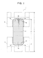
- FIG. 1 is a vertical sectional view showing a stator 1 of an electric motor according to the instant embodiment of the invention now under consideration.
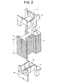
- Fig. 2 is an exploded perspective view showing the stator 1 of the electric motor according to the instant embodiment of the invention.
- the stator 1 of the electric motor according to the instant embodiment of the invention includes a stator core 4 having a substantially rectangular yoke portion 2 of a predetermined thickness and a magnetic pole tooth portion 3 projecting from the yoke portion 2, and a pair of insulative frame members 5 which are snugly fit onto the pole tooth portion 3 of the stator core 4 so as to cover and enclose the pole tooth portion.
- the stator core 4 is constituted by a plurality of core sheets 6 laminated or stacked in the direction thicknesswise of the stator core. Further, the stator 1 of the electric motor is implemented in an annular form by connecting the individual yoke portions 2 to one another, wherein a coated wire 7 such as an enameled wire is wound on and around the outer peripheral surfaces of the paired insulative frame members 5 in a coil-like form.
- the coated wire 7 If the coated wire 7 is bent steeply, fracture and deterioration will occur in the coating. Accordingly, the coated wire has to be wound with a predetermined gentle curvature.
- a predetermined gentle curvature By way of example, in the case of an enameled wire of 1.9 mm in diameter, it must be wound with a radius of curvature on the order of 30 mm.
- each of the corners 5a of both end portions of the paired insulative frame members 5 as viewed in the direction thicknesswise of the core is formed in a gently curved or rounded surface, while both end portions of the paired insulative frame members 5 in the direction thicknesswise of the core are formed in a thickness which is greater than that required indispensably from the standpoint of insulation.
- each of the corner portions of the pole tooth portion 3 of the stator core 4 is provided with offset portions 3a so that each of both end portions of the pole tooth portion has a narrower width as viewed in the direction thicknesswise of the core.
- each of the insulative frame members 5 is provided with a first groove portion 5b for accommodating therein a ridge portion 3b of the pole tooth portion 3 on one hand and second groove portions 5c for accommodating, respectively, shoulder portions 3c of the pole tooth portion 3 on the other hand.
- the ridge portion 3b of the pole tooth portion 3 can be snugly fit into the first groove portion 5b of each insulative frame member 5 while the shoulder portions 3c of the pole tooth portion 3 can be snugly fit into the second groove portions 5c, respectively, of the insulative frame member 5, whereby the ridge portion 3b of the pole tooth portion 3 can extend up to a position in the close vicinity of the end of the insulative frame member 5 as viewed in the direction thicknesswise of the core.
- the length L1 of the stator core 4 in the direction thicknesswise thereof relative to the overall height H of the stator 1 of the electric motor can be realized sufficiently great when compared with the length L2 of the stator core 13 of the conventional stator 10 shown in Figs.
- the stator 1 of the electric motor can produce a higher output torque with the same overall height H as the conventional stator 10.
- the offset portions 4a of the stator core 4 can be implemented in a simple structure in which the width of the core sheets 6 disposed at the upper and lower end portions, respectively, of the pole tooth portion 3 as viewed in the direction thicknesswise thereof is made shorter or narrower than the width of the core sheets 6 disposed at an intermediate portion of the pole tooth portion.
- the stator can be manufactured extremely easily when compared with the conventional stator described in Japanese Patent Application Laid-Open Publication No. 33397/2000, whereby the manufacturing efficiency or productivity can significantly be enhanced.
- the stator of the electric motor according to the present invention is capable of generating higher output torque with a same overall height as the stator of the conventional motor and thus the electric motor according to the present invention is suited for the applications where high output torque is demanded notwithstanding of limitation imposed in respect to the space available for the installation of the motor.
Landscapes
- Engineering & Computer Science (AREA)
- Power Engineering (AREA)
- Iron Core Of Rotating Electric Machines (AREA)
- Insulation, Fastening Of Motor, Generator Windings (AREA)
Abstract
In a stator of a conventional electric motor known
heretofore, thickness of the upper and lower end portions of paired
insulative frame members on which a coil is wound must be greater
than that required indispensably for ensuring insulation.
Consequently, length L2 of a stator core can not be assured
adequately relative to an overall height H of the stator, giving
rise to a problem that output torque is low.
In a stator 1 of an electric motor according to the
present invention, corner portions of a pole tooth portion 3 is
provided with offset portions 3a so that both end portions of the
pole tooth portion have a narrow width in the direction
thicknesswise thereof, while paired insulative frame members 5 are
provided with first groove portions 5b for accommodating ridge
portions 3b, respectively, of the pole tooth portion 3 and second
groove portions 5c for accommodating shoulder portions 3c,
respectively, of the pole tooth portion 3. Thus, ridge portions
3b of the pole tooth portion 3 can extend up to positions close
to both ends, respectively, of the paired insulative frame members
5 in the direction thicknesswise.
As a result, the length L1 of the stator core 4 in the
direction thicknesswise thereof can be made sufficiently great
relative to the overall height H of the stator 1 for ensuring high
output torque with adequate thickness of the insulative frame
members 5 required for the insulation.
Description
- The present invention relates to a stator of an electric motor having coils wound around individual magnetic pole tooth portions of a stator core with insulative frame members being interposed between the coils and the pole tooth portions, respectively.
- A structure of a
stator 10 of a conventional electric motor known heretofore is shown in Figs. 4 and 5. Figure 4 is a vertical sectional view showing astator 10 of the conventional electric motor. Further, Fig. 5 is an exploded perspective view showing thestator 10 of the conventional electric motor. As can be seen in these figures, thestator 10 of the conventional electric motor includes astator core member 13 having a substantially rectangular yoke portion 11 of a predetermined thickness and a magneticpole tooth portion 12 of a uniform width which projects from the yoke portion 11, and a pair ofinsulative frame members 14 which are snugly fit onto thepole tooth portion 12 of thestator core 13 so as to cover or enclose thepole tooth portion 12. A coated wire such as an enameled wire (not shown) is wound on and around the outer peripheral surfaces of the pairedinsulative frame members 14 in a coil-like form. - In general, if the coated wire is bent steeply, fracture and deterioration will occur in the coating. Accordingly, the coated wire has to be wound with a predetermined gentle curvature. By way of example, in the case of an enameled wire of 1.9 mm in diameter, it must be wound with the radius of curvature on the order of 30 mm.
- For the reason mentioned above, each of the corners of the upper and lower end portions of the paired
insulative frame members 14 must be so formed as to present a gently curved or rounded surface. Besides, the upper and lower end portions of the pairedinsulative frame members 14 have to be formed in a thickness which is greater than the thickness required essentially from the standpoint of insulation. As a result of this, it is impossible to realize an adequate length L2 of thestator core 13 in the direction thicknesswise thereof relative to the overall height H of thestator 10, giving rise to a problem that the available motor output torque is low. - A stator devised with a view to coping with the problem mentioned above is disclosed in Japanese Patent Application Laid-Open Publication No. 33397/2000. In this known stator, additional members are disposed on the upper and lower end portions, respectively, to thereby increase complementarily the length of the stator core in the direction thicknesswise thereof in an effort to make available a high output torque. However, with such stator structure, the members utterly differing from the stator core located intermediately must be mounted on the upper and lower end portions, respectively, of the stator core, which incur degradation in the productivity or manufacturing efficiency.
- With the present invention, it is contemplated to solve the problem such as described above by providing a stator of the electric motor which can ensure a higher output torque with a same overall height as the conventional stator.
- The stator of the electric motor according to the present invention which includes yoke portions each having a predetermined thickness and magnetic pole tooth portions projecting from the yoke portions, respectively, pairs of insulative frame members each fit onto each of the magnetic pole tooth portions of the stator core so as to cover the magnetic pole tooth portion from both ends of the magnetic pole tooth portion in a direction thicknesswise thereof, and coils each wound around each pair of the insulative frame members, characterized in that each of the magnetic pole tooth portions is provided with offset portions so that both end portions of each of the magnetic pole tooth portions have a narrow width as viewed in the direction thicknesswise thereof, and that the pair of insulative frame members have first groove portions for accommodating therein ridge portions, respectively, of the magnetic pole tooth portion and second groove portions for accommodating therein at least partially shoulder portions, respectively, of the magnetic pole tooth portion.
- In a stator implementation, the stator core features that it is constituted by a plurality of core sheets stacked in the direction thicknesswise of the stator core.
-
- Figure 1 is a vertical sectional view showing a stator of an electric motor according to the present invention.
- Figure 2 is an exploded perspective view showing a stator of the electric motor according to the present invention.
- Figure 3 is a front view showing partially in section a stator of an electric motor implemented in an annular structure according to the present invention.
- Figure 4 is a vertical sectional view showing a stator of a conventional electric motor.
- Figure 5 is an exploded perspective view showing the stator of the conventional electric motor.
-
- In the following, an exemplary embodiment of the present invention will be described. Figure 1 is a vertical sectional view showing a
stator 1 of an electric motor according to the instant embodiment of the invention now under consideration. Further, Fig. 2 is an exploded perspective view showing thestator 1 of the electric motor according to the instant embodiment of the invention. As can be seen in these figures, thestator 1 of the electric motor according to the instant embodiment of the invention includes astator core 4 having a substantiallyrectangular yoke portion 2 of a predetermined thickness and a magnetic pole tooth portion 3 projecting from theyoke portion 2, and a pair ofinsulative frame members 5 which are snugly fit onto the pole tooth portion 3 of thestator core 4 so as to cover and enclose the pole tooth portion. Thestator core 4 is constituted by a plurality ofcore sheets 6 laminated or stacked in the direction thicknesswise of the stator core. Further, thestator 1 of the electric motor is implemented in an annular form by connecting theindividual yoke portions 2 to one another, wherein a coatedwire 7 such as an enameled wire is wound on and around the outer peripheral surfaces of the pairedinsulative frame members 5 in a coil-like form. - If the coated
wire 7 is bent steeply, fracture and deterioration will occur in the coating. Accordingly, the coated wire has to be wound with a predetermined gentle curvature. By way of example, in the case of an enameled wire of 1.9 mm in diameter, it must be wound with a radius of curvature on the order of 30 mm. Under the circumstances, each of thecorners 5a of both end portions of the pairedinsulative frame members 5 as viewed in the direction thicknesswise of the core is formed in a gently curved or rounded surface, while both end portions of the pairedinsulative frame members 5 in the direction thicknesswise of the core are formed in a thickness which is greater than that required indispensably from the standpoint of insulation. - Further, each of the corner portions of the pole tooth portion 3 of the
stator core 4 is provided with offset portions 3a so that each of both end portions of the pole tooth portion has a narrower width as viewed in the direction thicknesswise of the core. Correspondingly, each of theinsulative frame members 5 is provided with afirst groove portion 5b for accommodating therein aridge portion 3b of the pole tooth portion 3 on one hand andsecond groove portions 5c for accommodating, respectively,shoulder portions 3c of the pole tooth portion 3 on the other hand. By virtue of this structure, theridge portion 3b of the pole tooth portion 3 can be snugly fit into thefirst groove portion 5b of eachinsulative frame member 5 while theshoulder portions 3c of the pole tooth portion 3 can be snugly fit into thesecond groove portions 5c, respectively, of theinsulative frame member 5, whereby theridge portion 3b of the pole tooth portion 3 can extend up to a position in the close vicinity of the end of theinsulative frame member 5 as viewed in the direction thicknesswise of the core. Thus, the length L1 of thestator core 4 in the direction thicknesswise thereof relative to the overall height H of thestator 1 of the electric motor can be realized sufficiently great when compared with the length L2 of thestator core 13 of theconventional stator 10 shown in Figs. 4 and 5 while ensuring for theinsulative frame members 5 the thickness which is demanded from the standpoints of insulation. Since the output torque of the motor is proportional to the length of thestator core 4 in the direction thicknesswise thereof, thestator 1 of the electric motor according to the instant embodiment of the invention can produce a higher output torque with the same overall height H as theconventional stator 10. - Additionally, the offset portions 4a of the
stator core 4 can be implemented in a simple structure in which the width of thecore sheets 6 disposed at the upper and lower end portions, respectively, of the pole tooth portion 3 as viewed in the direction thicknesswise thereof is made shorter or narrower than the width of thecore sheets 6 disposed at an intermediate portion of the pole tooth portion. Thus, the stator can be manufactured extremely easily when compared with the conventional stator described in Japanese Patent Application Laid-Open Publication No. 33397/2000, whereby the manufacturing efficiency or productivity can significantly be enhanced. - As is apparent from the foregoing, the stator of the electric motor according to the present invention is capable of generating higher output torque with a same overall height as the stator of the conventional motor and thus the electric motor according to the present invention is suited for the applications where high output torque is demanded notwithstanding of limitation imposed in respect to the space available for the installation of the motor.
Claims (2)
- A stator of an electric motor comprising a stator core comprised of yoke portions each having a predetermined thickness and magnetic pole tooth portions projecting from said yoke portions, respectively, pairs of insulative frame members each fit onto each of the magnetic pole tooth portions of said stator core so as to cover said magnetic pole tooth portion from both ends of said magnetic pole tooth portion in a direction thicknesswise thereof, and coils each wound around each pair of said insulative frame members,
characterized in that each of said magnetic pole tooth portions is provided with offset portions so that both end portions of each of said magnetic pole tooth portions have a narrow width as viewed in the direction thicknesswise thereof, and
that said pair of insulative frame members have first groove portions for accommodating therein ridge portions, respectively, of said magnetic pole tooth portion and second groove portions for accommodating therein at least partially shoulder portions, respectively, of said magnetic pole tooth portion. - A stator of an electric motor as set forth in claim 1, characterized in that said stator core is constituted by a plurality of core sheets stacked in the direction thicknesswise of said the stator core.
Applications Claiming Priority (1)
| Application Number | Priority Date | Filing Date | Title |
|---|---|---|---|
| PCT/JP2002/000680 WO2003065544A1 (en) | 2002-01-30 | 2002-01-30 | Stator of rotating electric motor |
Publications (2)
| Publication Number | Publication Date |
|---|---|
| EP1496596A1 true EP1496596A1 (en) | 2005-01-12 |
| EP1496596A4 EP1496596A4 (en) | 2007-12-05 |
Family
ID=27639260
Family Applications (1)
| Application Number | Title | Priority Date | Filing Date |
|---|---|---|---|
| EP02710379A Withdrawn EP1496596A4 (en) | 2002-01-30 | 2002-01-30 | STATOR OF ELECTRIC MOTOR ROTATING |
Country Status (5)
| Country | Link |
|---|---|
| EP (1) | EP1496596A4 (en) |
| JP (1) | JPWO2003065544A1 (en) |
| KR (1) | KR20030087035A (en) |
| CN (1) | CN1494757A (en) |
| WO (1) | WO2003065544A1 (en) |
Cited By (9)
| Publication number | Priority date | Publication date | Assignee | Title |
|---|---|---|---|---|
| FR2926935A1 (en) * | 2008-01-30 | 2009-07-31 | Tecddis Sarl | AXIAL FLUX AND PERMANENT MAGNET ELECTRIC MACHINE |
| EP2360813A1 (en) * | 2010-02-12 | 2011-08-24 | Hansjörg Cueni | Dynamoelectric machine |
| ITBO20100584A1 (en) * | 2010-09-29 | 2012-03-30 | Magneti Marelli Spa | ELECTRIC MACHINE PRESENTING A STATIC ROLL WITH RIGID BARS AND ITS CONSTRUCTION METHOD |
| WO2012130752A3 (en) * | 2011-04-01 | 2013-05-23 | Wobben Properties Gmbh | Pole shoe of a generator, preferably a generator of a wind turbine generator system |
| EP2882080A1 (en) * | 2013-12-06 | 2015-06-10 | Siemens Aktiengesellschaft | Dynamo-electric rotary machine |
| DE102014206847A1 (en) | 2014-04-09 | 2015-10-15 | Zf Friedrichshafen Ag | Stator of a rotating electrical machine |
| DE102014212119A1 (en) * | 2014-06-24 | 2015-12-24 | Schaeffler Technologies AG & Co. KG | Arrangement for electrical insulation of a coil winding |
| US20190238022A1 (en) * | 2018-01-26 | 2019-08-01 | Milwaukee Electric Tool Corporation | Stepped stator for an electric motor |
| KR20210021070A (en) * | 2018-07-27 | 2021-02-24 | 미쓰비시덴키 가부시키가이샤 | Electric motors, compressors and air conditioning units |
Families Citing this family (19)
| Publication number | Priority date | Publication date | Assignee | Title |
|---|---|---|---|---|
| JP2005057931A (en) * | 2003-08-06 | 2005-03-03 | Honda Motor Co Ltd | Stator |
| FR2859578B1 (en) * | 2003-09-10 | 2006-03-31 | Leroy Somer Moteurs | ROTATING ELECTRIC MACHINE COMPRISING A STATOR AND PROVISIONS FOR FIXING THE INSULATION THEREON |
| JP2005348552A (en) * | 2004-06-04 | 2005-12-15 | Nissan Motor Co Ltd | Stator structure of axial gap type rotating electrical machine |
| JP4826718B2 (en) * | 2004-07-27 | 2011-11-30 | 日本電産株式会社 | Armature for motor and motor |
| JP2007244065A (en) * | 2006-03-07 | 2007-09-20 | Nissan Motor Co Ltd | Stator structure of concentrated winding motor |
| DE112011104964T5 (en) * | 2011-02-25 | 2013-11-21 | Mitsubishi Electric Corporation | Stator for a rotating electrical machine and associated manufacturing method |
| KR20130012719A (en) * | 2011-07-26 | 2013-02-05 | 현대모비스 주식회사 | Bobbin of motor for vehicle |
| JP2014011900A (en) * | 2012-06-29 | 2014-01-20 | Nidec Sankyo Corp | Stator and motor |
| JP2014161185A (en) * | 2013-02-20 | 2014-09-04 | Mitsubishi Electric Corp | Rotary electric machine and air blower including the same |
| CN103701283A (en) * | 2014-01-16 | 2014-04-02 | 欧明方 | Hollow energy saving motor |
| JP6469954B2 (en) * | 2014-03-07 | 2019-02-13 | オリエンタルモーター株式会社 | Hybrid stepping motor |
| JP6103559B1 (en) * | 2015-11-30 | 2017-03-29 | 三菱電機株式会社 | Rotating electric machine |
| KR102068991B1 (en) * | 2016-04-12 | 2020-01-22 | 미쓰비시덴키 가부시키가이샤 | Electric motors, compressors, and refrigeration cycle units |
| CN107786021B (en) * | 2016-08-29 | 2019-10-11 | 光宝电子(广州)有限公司 | Insulating sleeve with around wire work |
| CN107359707B (en) * | 2017-08-28 | 2023-09-15 | 广东美芝制冷设备有限公司 | Iron core components, motor stators, motors and compressors |
| EP3955432B1 (en) * | 2019-05-28 | 2025-09-24 | Guangdong Welling Auto Parts Co., Ltd. | Iron core assembly, electric motor, compressor and vehicle |
| CN112018922B (en) * | 2019-05-28 | 2025-09-12 | 广东威灵汽车部件有限公司 | Core components, motors, compressors and vehicles |
| JP2023006461A (en) * | 2021-06-30 | 2023-01-18 | 株式会社ミツバ | motor device |
| CN120566730A (en) * | 2024-02-29 | 2025-08-29 | 美的威灵电机技术(上海)有限公司 | Motors and household appliances |
Family Cites Families (8)
| Publication number | Priority date | Publication date | Assignee | Title |
|---|---|---|---|---|
| JPS5397303U (en) * | 1976-12-06 | 1978-08-08 | ||
| JPS5736554A (en) * | 1980-08-13 | 1982-02-27 | Hitachi Ltd | KOIRUBOBIN |
| JPH01159557U (en) * | 1988-04-26 | 1989-11-06 | ||
| JPH0716557U (en) * | 1993-08-18 | 1995-03-17 | 国産電機株式会社 | Laminated iron core for rotating machinery |
| JPH10112963A (en) * | 1996-10-07 | 1998-04-28 | Mitsubishi Electric Corp | Electric motor |
| JPH1189128A (en) * | 1997-09-12 | 1999-03-30 | Toshiba Corp | Stator of electric motor and method of manufacturing the same |
| JP3451263B2 (en) * | 1998-08-28 | 2003-09-29 | 三菱電機株式会社 | Stator |
| JP2000139052A (en) * | 1998-11-02 | 2000-05-16 | Matsushita Electric Ind Co Ltd | Motor stator |
-
2002
- 2002-01-30 CN CNA028058380A patent/CN1494757A/en active Pending
- 2002-01-30 WO PCT/JP2002/000680 patent/WO2003065544A1/en not_active Ceased
- 2002-01-30 JP JP2003565013A patent/JPWO2003065544A1/en active Pending
- 2002-01-30 KR KR10-2003-7012769A patent/KR20030087035A/en not_active Ceased
- 2002-01-30 EP EP02710379A patent/EP1496596A4/en not_active Withdrawn
Non-Patent Citations (2)
| Title |
|---|
| No further relevant documents disclosed * |
| See also references of WO03065544A1 * |
Cited By (15)
| Publication number | Priority date | Publication date | Assignee | Title |
|---|---|---|---|---|
| WO2009095612A3 (en) * | 2008-01-30 | 2010-02-11 | Tecddis | Electric machine having axial flux and permanent magnets |
| US8791616B2 (en) | 2008-01-30 | 2014-07-29 | Ddis, S.A.S. | Electric machine with axial flux and permanent magnets |
| FR2926935A1 (en) * | 2008-01-30 | 2009-07-31 | Tecddis Sarl | AXIAL FLUX AND PERMANENT MAGNET ELECTRIC MACHINE |
| EP2360813A1 (en) * | 2010-02-12 | 2011-08-24 | Hansjörg Cueni | Dynamoelectric machine |
| ITBO20100584A1 (en) * | 2010-09-29 | 2012-03-30 | Magneti Marelli Spa | ELECTRIC MACHINE PRESENTING A STATIC ROLL WITH RIGID BARS AND ITS CONSTRUCTION METHOD |
| TWI509945B (en) * | 2011-04-01 | 2015-11-21 | Wobben Aloys | Pole shoe of a generator, preferably a generator of a wind power installation |
| WO2012130752A3 (en) * | 2011-04-01 | 2013-05-23 | Wobben Properties Gmbh | Pole shoe of a generator, preferably a generator of a wind turbine generator system |
| US9742224B2 (en) | 2011-04-01 | 2017-08-22 | Wobben Properties Gmbh | Pole shoe of a generator, preferably a generator of a wind turbine generator system |
| EP2882080A1 (en) * | 2013-12-06 | 2015-06-10 | Siemens Aktiengesellschaft | Dynamo-electric rotary machine |
| DE102014206847A1 (en) | 2014-04-09 | 2015-10-15 | Zf Friedrichshafen Ag | Stator of a rotating electrical machine |
| DE102014212119A1 (en) * | 2014-06-24 | 2015-12-24 | Schaeffler Technologies AG & Co. KG | Arrangement for electrical insulation of a coil winding |
| US20190238022A1 (en) * | 2018-01-26 | 2019-08-01 | Milwaukee Electric Tool Corporation | Stepped stator for an electric motor |
| KR20210021070A (en) * | 2018-07-27 | 2021-02-24 | 미쓰비시덴키 가부시키가이샤 | Electric motors, compressors and air conditioning units |
| EP3832849A4 (en) * | 2018-07-27 | 2021-08-25 | Mitsubishi Electric Corporation | ELECTRIC MOTOR, COMPRESSOR AND AIR CONDITIONING |
| US11804739B2 (en) | 2018-07-27 | 2023-10-31 | Mitsubishi Electric Corporation | Motor having stator and rotor configured to reduce eddy current loss, and compressor and air conditioner incorporating same |
Also Published As
| Publication number | Publication date |
|---|---|
| EP1496596A4 (en) | 2007-12-05 |
| KR20030087035A (en) | 2003-11-12 |
| JPWO2003065544A1 (en) | 2005-05-26 |
| WO2003065544A1 (en) | 2003-08-07 |
| CN1494757A (en) | 2004-05-05 |
Similar Documents
| Publication | Publication Date | Title |
|---|---|---|
| EP1496596A1 (en) | Stator of rotating electric motor | |
| US8018115B2 (en) | Alignment of segmented stators for electric machines | |
| US9197102B2 (en) | Stator assembly for motor having hall sensor part fixed to end of tooth of stator | |
| JP7209264B2 (en) | Insulators and stators and motors equipped with them | |
| US10291087B2 (en) | Electric motor | |
| JP2008278632A (en) | Split stator and split stator manufacturing method | |
| JPH11122855A (en) | Coil bobbin for stator and electric motor | |
| JP7289102B2 (en) | Insulators and stators and motors equipped with them | |
| JP2022175072A (en) | motor | |
| US12506370B2 (en) | Motor formed with a distributed winding coil | |
| US7750528B2 (en) | Actuator and coil frame | |
| US20100289375A1 (en) | Stator Core | |
| JPH07111747A (en) | Electric motor stator | |
| CN105052014B (en) | Electric motor and its manufacturing method | |
| JP2009148141A (en) | Magnetic parts | |
| JPH09168251A (en) | Step motor stator and manufacturing method | |
| JPH064564Y2 (en) | Coil block | |
| JP3130092B2 (en) | Motor stator | |
| KR100492594B1 (en) | Bobbin structure for reciprocating motor | |
| JP2002369433A (en) | Magnet motor | |
| JP2698591B2 (en) | Stator of induction motor and method of manufacturing the same | |
| JPH0736676B2 (en) | Electric motor stator | |
| JP2596526Y2 (en) | Flexible coil with printed circuit board for motor | |
| JPH053651A (en) | Electric motor | |
| JPH023148U (en) |
Legal Events
| Date | Code | Title | Description |
|---|---|---|---|
| PUAI | Public reference made under article 153(3) epc to a published international application that has entered the european phase |
Free format text: ORIGINAL CODE: 0009012 |
|
| 17P | Request for examination filed |
Effective date: 20030615 |
|
| AK | Designated contracting states |
Kind code of ref document: A1 Designated state(s): AT BE CH CY DE DK ES FI FR GB GR IE IT LI LU MC NL PT SE TR |
|
| RAP1 | Party data changed (applicant data changed or rights of an application transferred) |
Owner name: MITSUBISHI DENKI KABUSHIKI KAISHA |
|
| A4 | Supplementary search report drawn up and despatched |
Effective date: 20071106 |
|
| 17Q | First examination report despatched |
Effective date: 20080310 |
|
| STAA | Information on the status of an ep patent application or granted ep patent |
Free format text: STATUS: THE APPLICATION IS DEEMED TO BE WITHDRAWN |
|
| 18D | Application deemed to be withdrawn |
Effective date: 20080722 |