EP1498332A1 - Dispositif de protection contre les freinages intempestifs spécialement adapté à un frein électromécanique - Google Patents
Dispositif de protection contre les freinages intempestifs spécialement adapté à un frein électromécanique Download PDFInfo
- Publication number
- EP1498332A1 EP1498332A1 EP04291484A EP04291484A EP1498332A1 EP 1498332 A1 EP1498332 A1 EP 1498332A1 EP 04291484 A EP04291484 A EP 04291484A EP 04291484 A EP04291484 A EP 04291484A EP 1498332 A1 EP1498332 A1 EP 1498332A1
- Authority
- EP
- European Patent Office
- Prior art keywords
- braking
- actuator
- signal
- brake
- pusher
- Prior art date
- Legal status (The legal status is an assumption and is not a legal conclusion. Google has not performed a legal analysis and makes no representation as to the accuracy of the status listed.)
- Granted
Links
Images

Classifications
-
- B—PERFORMING OPERATIONS; TRANSPORTING
- B60—VEHICLES IN GENERAL
- B60T—VEHICLE BRAKE CONTROL SYSTEMS OR PARTS THEREOF; BRAKE CONTROL SYSTEMS OR PARTS THEREOF, IN GENERAL; ARRANGEMENT OF BRAKING ELEMENTS ON VEHICLES IN GENERAL; PORTABLE DEVICES FOR PREVENTING UNWANTED MOVEMENT OF VEHICLES; VEHICLE MODIFICATIONS TO FACILITATE COOLING OF BRAKES
- B60T8/00—Arrangements for adjusting wheel-braking force to meet varying vehicular or ground-surface conditions, e.g. limiting or varying distribution of braking force
-
- B—PERFORMING OPERATIONS; TRANSPORTING
- B60—VEHICLES IN GENERAL
- B60T—VEHICLE BRAKE CONTROL SYSTEMS OR PARTS THEREOF; BRAKE CONTROL SYSTEMS OR PARTS THEREOF, IN GENERAL; ARRANGEMENT OF BRAKING ELEMENTS ON VEHICLES IN GENERAL; PORTABLE DEVICES FOR PREVENTING UNWANTED MOVEMENT OF VEHICLES; VEHICLE MODIFICATIONS TO FACILITATE COOLING OF BRAKES
- B60T13/00—Transmitting braking action from initiating means to ultimate brake actuator with power assistance or drive; Brake systems incorporating such transmitting means, e.g. air-pressure brake systems
- B60T13/74—Transmitting braking action from initiating means to ultimate brake actuator with power assistance or drive; Brake systems incorporating such transmitting means, e.g. air-pressure brake systems with electrical assistance or drive
-
- B—PERFORMING OPERATIONS; TRANSPORTING
- B60—VEHICLES IN GENERAL
- B60T—VEHICLE BRAKE CONTROL SYSTEMS OR PARTS THEREOF; BRAKE CONTROL SYSTEMS OR PARTS THEREOF, IN GENERAL; ARRANGEMENT OF BRAKING ELEMENTS ON VEHICLES IN GENERAL; PORTABLE DEVICES FOR PREVENTING UNWANTED MOVEMENT OF VEHICLES; VEHICLE MODIFICATIONS TO FACILITATE COOLING OF BRAKES
- B60T8/00—Arrangements for adjusting wheel-braking force to meet varying vehicular or ground-surface conditions, e.g. limiting or varying distribution of braking force
- B60T8/32—Arrangements for adjusting wheel-braking force to meet varying vehicular or ground-surface conditions, e.g. limiting or varying distribution of braking force responsive to a speed condition, e.g. acceleration or deceleration
- B60T8/88—Arrangements for adjusting wheel-braking force to meet varying vehicular or ground-surface conditions, e.g. limiting or varying distribution of braking force responsive to a speed condition, e.g. acceleration or deceleration with failure responsive means, i.e. means for detecting and indicating faulty operation of the speed responsive control means
- B60T8/885—Arrangements for adjusting wheel-braking force to meet varying vehicular or ground-surface conditions, e.g. limiting or varying distribution of braking force responsive to a speed condition, e.g. acceleration or deceleration with failure responsive means, i.e. means for detecting and indicating faulty operation of the speed responsive control means using electrical circuitry
-
- B—PERFORMING OPERATIONS; TRANSPORTING
- B60—VEHICLES IN GENERAL
- B60T—VEHICLE BRAKE CONTROL SYSTEMS OR PARTS THEREOF; BRAKE CONTROL SYSTEMS OR PARTS THEREOF, IN GENERAL; ARRANGEMENT OF BRAKING ELEMENTS ON VEHICLES IN GENERAL; PORTABLE DEVICES FOR PREVENTING UNWANTED MOVEMENT OF VEHICLES; VEHICLE MODIFICATIONS TO FACILITATE COOLING OF BRAKES
- B60T2270/00—Further aspects of brake control systems not otherwise provided for
- B60T2270/40—Failsafe aspects of brake control systems
- B60T2270/414—Power supply failure
Definitions
- the invention relates to a protective device against inadvertent braking especially adapted to an electromechanical brake.
- document FR-A-2 790 730 which describes a device protection against inadvertent braking, including a security system comprising a software path which is configured to activate a general valve and a material path that is configured to inhibit this general valve.
- a security system comprising a software path which is configured to activate a general valve and a material path that is configured to inhibit this general valve.
- US-A-6 513 885 which teaches a redundant braking circuit arrangement.
- Electromechanical type brakes include a pile of disks and one or more actuators electromechanical devices arranged next to the battery discs, said actuators having a pusher to press the stack of disks.
- the pusher is operated by an electric motor controlled by a control module of the actuator, which, in response to an instruction from brake generated by a brake computer, sends a modulation order of power to a module of power that delivers the power required to the engine of the actuator.
- the object of the invention is to propose a protection improved against the untimely maneuvers of the push of an electromechanical brake.
- the invention relates to a protective device against inadvertent braking especially adapted to an electromechanical brake comprising at least one actuator having a pusher adapted to be moved by means of a electric motor controlled by a control module for squeezing a stack of disks in a controlled manner, device comprising according to the invention a safety organ can be placed in a first state in which it prevents the pusher from being moved by the motor electric and a second state in which he leaves free the pusher to be moved by the electric motor, the safety organ being controlled by a logic of command that places the security organ by default the first state and does not place the security organ in the second state than in response to the simultaneous presence of a order from the control module and a signal from confirmation not coming from the control module and independent of it.
- the device of the invention therefore greatly increases the safety of the vehicle's braking system.
- the confirmation signal is a braking signal active from a braking calculator which, moreover, delivers a braking instruction to the control module of the actuator.
- the confirmation signal is a signal pedal from a powered brake pedal by the pilot.
- the safety member is a locking member mechanical actuator mounted on the actuator, elsewhere intended to lock the actuator in position park braking.
- the locking member is a brake to lack of current otherwise used to maintain a park effort.
- the safety member is a switch of power arranged on a power supply line of the electric motor of the actuator.
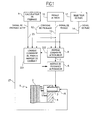
- electromechanical brake 1 has an stack of disks 2 with alternating disks integral in rotation of the wheel to brake and disks fixed in rotation.
- the brake 1 comprises a plurality of actuators 3 (only one is shown here) who are worn by a crown 4 to extend facing the stack of disks 2.
- Each actuator 3 comprises a pusher 5 capable of being moved to disk stack 2 to press it and thus generate a braking force.
- the pusher 5 is moved by an electric motor via a kinematic chain transforming a movement of rotation of the electric motor in a movement of translation of the pusher 5.
- the electric motor is powered via a module of the power of the actuator 6 which delivers to the engine a electrical power according to an order 7 issued by a control module of the actuator 8.
- the orders issued by the control module of the actuator 8 are developed from various signals, coming in particular from a braking computer 9, a brake pedal 10 and a park selector 11.
- the entire braking system of the aircraft is intended to operate in three modes: a mode normal, an emergency mode, and a park mode.
- control module of the actuator 8 In the normal mode, the control module of the actuator 8 generates an order 7 according to a set point braking circuit 12 received from the braking computer 9.
- the control module In the emergency mode, in which the calculator braking system has failed, the control module the actuator 8 generates an order 7 according to a signal pedal 13 representative of the depression of the pedal brake 10 actuated directly by the pilot.
- the actuator control module 8 In park mode, priority over other modes, the actuator control module 8 generates a park brake command 7 in response to a signal park 14 issued when the selector is operated 11 by the pilot. To maintain the park braking while the aircraft is stationary, the actuator 3 is equipped with a brake for lack of current 15 which, when not powered, blocks the pusher 5 in position, blocking one of the driveshafts of the kinematic chain between the electric motor and the pusher 5.
- a current-canceling brake as locking member is particularly suitable because it allows a maintenance of the park effort without any power consumption.
- the safety equipment against inadvertent braking is constituted by the power failure brake 15 itself.
- the power loss brake is controlled by a control logic 221 which, by default, cuts the supply of the current-canceling brake 15, which has to block the pusher 5.
- the control logic 221 is arranged to supply the current brake 15 (and thus unlock the pusher 5) only in response to an unlock command 222 from the actuator control module 8, confirmed by a confirmation signal not coming from not the control module of the actuator 8 and independent of it.
- control logic 221 of the current-canceling brake 15 makes it possible to manage the latter as well to ensure park braking as for to provide according to the invention a locking of the actuator when it is idle, to avoid any braking untimely.
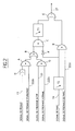
- the control logic 221 of the brake for lack of Current 15 is detailed below.
- the control module of the actuator 8 generates then an order 7 to the power module of the actuator 6 to cause the displacement of the pusher 5 to apply on the stack of disks 2 an effort determined park. Once this park effort is applied, the control module of the actuator 8 reverses the signal park brake 222c, which cuts off the power supply current-canceling brake 15. Thus deprived of power supply, the power-down brake 15 locks the actuator. The control module of the actuator 8 then interrupts order 7 to the power module of the actuator 6.
- the control module of the actuator 8 When disengaging the park selector 11 by the pilot, the control module of the actuator 8 generates an order 7 to the power module of the actuator 6, so that the pusher 5 exerts on the stack of disks 2 an effort equivalent to the effort of park, then the actuator control module 8 generates a brake signal park 222c.
- a timer T2 active only when the park selector 11 goes from the engaged state to the disengaged state delays the change of state of the signal 14.
- said signal still remains at its former value so that braking signal generation park 222c by the control module of the actuator 8 therefore, via the D and E doors, to generate a signal control 27 which allows the supply of the brake break of current 15.
- the brake a lack of current 15 unlocks the actuator.
- the control module of the actuator 8 generates an order 7 to the power module of the actuator 6 to move the pusher 5 away from the stack 2.
- the module actuator control 8 reverses braking signal 222c, which has the effect of interrupting supply of the current-canceling brake 15.
- the power supply brake 15 locks the actuator.
- the timer T2 is useful for leaving the time to the control module of the actuator 8 to proceed 5. If the signal processed by the door D immediately went to a representative value disengagement of the actuator, the output of the door D would immediately become null and would cause immediate locking of the actuator. The module actuator 8 would then not have the time to remove the pusher 5.
- the brake is used current 15 not only for park braking, but also to protect the aircraft against braking untimely when the braking system is in normal braking mode or in emergency braking mode.
- the control module of the actuator 8 When operating in normal braking mode, the control module of the actuator 8 generates a normal braking signal 222a.
- the calculator braking 9 sends a braking instruction 12 to the module of the actuator 8, it generates at the same time a active braking signal 23.
- the normal braking signal 222a and the signal of active braking 23 are treated by an AND gate referenced G, whose output is processed by the referenced OR gate B and the AND gate referenced C, then finally by the OR gate referenced E to generate an order 27 power supply of the power failure brake 15.
- Gate B is processed at the level of door C with a signal coming from the door NO referenced F whose function is to invert the signal of park 14, so that the exit of the door C is positive only if the park signal 14 is in a state indicating that the park selector 11 is disengaged.
- the presence of the braking signal active 23 allows the generation of a control signal 27 supply of the current-canceling brake 15.
- the current-canceling brake 15 unlocks the actuator, which allows the control module to the actuator 8 to control the braking according to the braking setpoint 12 from braking computer 9.
- the calculator brake 9 cancels the active braking signal 23.
- the same doors G, B, C, E reverse the control signal 27, which interrupts the supply of the brake to lack of power 15.
- the current-breaking brake 15 therefore locks the actuator. This lock prevents any movement of the pusher 5, and therefore any unwanted braking.
- a delay T1 allows to leave time to the control module of the actuator 8 to proceed to removing the pusher 5 before interlocking of the actuator.
- a timer is preferred to a combination with a signal indicative of the position actuator or actuator operation, for reasons of segregation between the management of the actuator and that of the power-vacuum brake.
- the module of the actuator 8 when operating in emergency mode, when the brake computer 9 is faulty, the module of the actuator 8 generates a signal of emergency brake 222b which is treated by an AND gate referenced A located upstream of the door B.
- This signal causes the generation of a command signal 27 power supply of the power failure brake 15 when a pedal signal 13 is generated by an action of the driver on the brake pedal 10.
- a referenced comparator H allows to take into account the pedal signal 13 only if it exceeds a predetermined threshold.
- This lock prevents any movement of the pusher 5, and therefore any unwanted braking due to a malfunction braking computer or module ordered.
- the control logic of the switch 21 places by default the switch 20 in an open state for which the power module of the actuator 6 is not powered. In this state, the pusher 5 of the actuator 3 can not move in response to an order of the module of actuator control 8.
- the control logic of the switch 21 is arranged to place the switch 20 in a closed state only in response to a close order 22 from of the control module of the actuator 8, confirmed by a confirmation signal not coming from the module controlling the actuator 8 and independent thereof.
- the signal of The aforementioned confirmation may be issued by different bodies.
- the confirmation signal is a active braking signal 23 issued by the computer of 9, which indicates that the braking calculator is issuing a braking instruction which imposes a displacement of the pusher 5.
- This braking signal active can be simply the braking setpoint 12 itself, or be developed from the instructions of the braking.
- the power switch 20 is in an open state and the actuator 3 is not powered, which prevents any inadvertent movement of the pusher 5.
- the confirmation signal is the pedal signal 13.
- the power switch 20 is in an open state and the actuator 3 is not powered, which avoids any displacement inadvertent pusher 5.
- the power switch 20 has here been placed in upstream of the power module of the actuator 6, but it could also be placed downstream of it.
Landscapes
- Engineering & Computer Science (AREA)
- Transportation (AREA)
- Mechanical Engineering (AREA)
- Regulating Braking Force (AREA)
- Valves And Accessory Devices For Braking Systems (AREA)
- Braking Arrangements (AREA)
- Braking Systems And Boosters (AREA)
Abstract
Description
- la figure 1 est un schéma-bloc d'un circuit de freinage d'un aéronef équipé d'un dispositif de protection contre les freinages intempestifs selon un premier mode de réalisation de l'invention, faisant appel à un frein à manque de courant;
- la figure 2 est un schéma d'une logique de commande du frein à manque de courant de ce premier mode de réalisation de l'invention illustré à la figure 1 ;
- la figure 3 est un schéma-bloc d'un circuit de freinage d'un aéronef équipé d'un dispositif de protection contre les freinages intempestifs selon un deuxième mode de réalisation de l'invention, faisant appel à un interrupteur de puissance.
- des ordres de déblocage 222 provenant du module de commande de l'actionneur 8 et constitués, selon le mode de fonctionnement dans lequel se trouve le système de freinage de l'aéronef, d'un signal de freinage normal 222a, d'un signal de freinage d'urgence 222b, ou d'un signal de freinage de parc 222c;
- le signal de freinage actif 23, généré par le calculateur de freinage 9 ;
- le signal de pédale 13 en provenance d'un potentiomètre équipant la pédale de frein 10 située dans le cockpit et actionnée par le pilote;
- le signal de parc 14 en provenance du sélecteur de parc 11 situé dans le cockpit et actionné par le pilote.
Claims (6)
- Dispositif de protection contre les freinages intempestifs spécialement adapté à un frein électromécanique comprenant au moins un actionneur (3) ayant un poussoir (5) apte à être déplacé au moyen d'un moteur électrique commandé par un module de commande (8) pour presser de façon commandée une pile de disques (2), caractérisé en ce que le dispositif comporte un organe de sécurité (15 ;20) pouvant être placé dans un premier état dans lequel il empêche le poussoir (5) d'être déplacé par le moteur électrique et un second état dans lequel il laisse le poussoir (5) libre d'être déplacé par le moteur électrique, l'organe de sécurité (15 ;20) étant commandé par une logique de commande (221 ;21) qui place par défaut l'organe de sécurité (15 ;20) dans le premier état et ne place l'organe de sécurité dans le second état qu'en réponse à la présence simultanée d'un ordre (222 ;22) provenant du module de commande (8) et d'un signal de confirmation (13 ;14 ;23) ne provenant pas du module de commande (8) et indépendant de celui-ci.
- Dispositif selon la revendication 1, caractérisé en ce que, dans une situation de freinage normal, le signal de confirmation est un signal de freinage actif (23) en provenance d'un calculateur de freinage (9) qui, par ailleurs, délivre une consigne de freinage (12) au module de commande (8) de l'actionneur.
- Dispositif selon la revendication 2, caractérisé en ce que, dans une situation de freinage d'urgence où le calculateur de freinage (9) est défaillant, le signal de confirmation est un signal de pédale (13) en provenance d'une pédale de frein (10) actionnée par le pilote.
- Dispositif selon l'une des revendications 1 à 3, caractérisé en ce que l'organe de sécurité est un organe de blocage (15) du poussoir (5) monté sur l'actionneur, par ailleurs destiné à bloquer l'actionneur en position de freinage de parc.
- Dispositif selon la revendication 4, caractérisé en ce que l'organe de blocage est un frein à manque de courant (15).
- Dispositif selon l'une des revendications 1 à 3, caractérisé en ce que l'organe de sécurité est un interrupteur de puissance (20) disposé sur une ligne d'alimentation en puissance de l'actionneur.
Applications Claiming Priority (2)
| Application Number | Priority Date | Filing Date | Title |
|---|---|---|---|
| FR0308650 | 2003-07-16 | ||
| FR0308650A FR2857642B1 (fr) | 2003-07-16 | 2003-07-16 | Dispositif de protection contre les freinages intempestifs specialement adapte a un frein electromecanique |
Publications (2)
| Publication Number | Publication Date |
|---|---|
| EP1498332A1 true EP1498332A1 (fr) | 2005-01-19 |
| EP1498332B1 EP1498332B1 (fr) | 2006-03-01 |
Family
ID=33462533
Family Applications (1)
| Application Number | Title | Priority Date | Filing Date |
|---|---|---|---|
| EP04291484A Expired - Lifetime EP1498332B1 (fr) | 2003-07-16 | 2004-06-14 | Dispositif de protection contre les freinages intempestifs spécialement adapté à un frein électromécanique |
Country Status (7)
| Country | Link |
|---|---|
| US (1) | US7213891B2 (fr) |
| EP (1) | EP1498332B1 (fr) |
| AT (1) | ATE318740T1 (fr) |
| CA (1) | CA2475030C (fr) |
| DE (1) | DE602004000438T2 (fr) |
| ES (1) | ES2258755T3 (fr) |
| FR (1) | FR2857642B1 (fr) |
Cited By (5)
| Publication number | Priority date | Publication date | Assignee | Title |
|---|---|---|---|---|
| WO2008071437A3 (fr) * | 2006-12-15 | 2008-10-09 | Ipgate Ag | Réduction adaptative de course à vide |
| EP2090480A1 (fr) * | 2008-02-14 | 2009-08-19 | Messier-Bugatti | Procédé de gestion d'alimentation d'un actionneur irréversible de frein de roue de véhicule |
| WO2011110363A1 (fr) * | 2010-03-12 | 2011-09-15 | Messier-Bugatti | Procede de gestion d'un systeme de freinage pour aeronef equipe de freins electromecaniques. |
| FR2992288A1 (fr) * | 2012-06-25 | 2013-12-27 | Messier Bugatti Dowty | Procede de deblocage d'un frein de roue d'aeronef |
| EP3176083A1 (fr) * | 2015-12-01 | 2017-06-07 | Safran Landing Systems | Architecture de systeme de freinage pour aeronef |
Families Citing this family (14)
| Publication number | Priority date | Publication date | Assignee | Title |
|---|---|---|---|---|
| JP4418259B2 (ja) * | 2004-02-27 | 2010-02-17 | 株式会社日立製作所 | 電動ブレーキ装置 |
| FR2880855B1 (fr) * | 2005-01-14 | 2007-04-06 | Messier Bugatti Sa | Dispositif de protection contre les freinages intempestifs pour un frein a actionneurs electromecaniques |
| US7437231B2 (en) * | 2005-02-14 | 2008-10-14 | Honeywell International Inc. | Brake system providing at least one enable signal to brake controllers and method of using same |
| US7784882B2 (en) * | 2006-09-26 | 2010-08-31 | The Boeing Company | Power interrupt management for an aircraft electric brake system |
| FR2932158B1 (fr) * | 2008-06-04 | 2011-04-01 | Messier Bugatti | Circuit de freinage electrique muni de moyens pour commander les organes de blocage des poussoirs d'actionneurs electromecanique equipant un frein d'aeronef |
| FR2973776B1 (fr) | 2011-04-07 | 2013-04-05 | Messier Bugatti | Architecture de systeme de freinage pour aeronef. |
| US9039102B2 (en) * | 2011-09-08 | 2015-05-26 | Goodrich Corporation | Systems and methods for emergency braking system |
| FR2988373B1 (fr) * | 2012-03-21 | 2014-04-25 | Messier Bugatti Dowty | Systeme de freinage electromecanique pour aeronef |
| FR2997379B1 (fr) * | 2012-10-26 | 2015-02-27 | Messier Bugatti Dowty | Systeme de maintien d'effort de presse par action combinee de deux organes. |
| FR3016325B1 (fr) * | 2014-01-10 | 2016-02-12 | Messier Bugatti Dowty | Procede de surveillance d`un organe de blocage, et actionneur electromecanique. |
| US20160306278A1 (en) * | 2015-04-20 | 2016-10-20 | Tokyo Ohka Kogyo Co., Ltd. | Chemical for photolithography with improved liquid transfer property and resist composition comprising the same |
| KR102539406B1 (ko) * | 2019-04-22 | 2023-06-01 | 히다치 아스테모 가부시키가이샤 | 제어 장치 |
| CN113799975B (zh) * | 2021-08-18 | 2022-11-11 | 西安航空制动科技有限公司 | 一种基于fpga的飞机刹车控制器 |
| DE102023200458B4 (de) * | 2023-01-20 | 2024-12-05 | Zf Cv Systems Global Gmbh | Elektronischer Schaltkreis |
Citations (2)
| Publication number | Priority date | Publication date | Assignee | Title |
|---|---|---|---|---|
| FR2790730A1 (fr) * | 1999-02-01 | 2000-09-15 | Aircraft Braking Systems Corp | Systeme de commande de frein electrique a securite positive |
| US6513885B1 (en) * | 1999-05-14 | 2003-02-04 | Hydro-Aire, Inc. | Dual redundant active/active brake-by-wire architecture |
Family Cites Families (5)
| Publication number | Priority date | Publication date | Assignee | Title |
|---|---|---|---|---|
| JP2835173B2 (ja) * | 1990-11-13 | 1998-12-14 | 本田技研工業株式会社 | 車両のブレーキ制御装置 |
| DE4422664A1 (de) * | 1993-07-03 | 1995-03-09 | Peter Luepges | Vorrichtung zum Bremsen |
| DE19743305C2 (de) * | 1997-09-30 | 2001-03-15 | Siemens Ag | Anordnung zur Sicherstellung des Lösens einer selbsthemmenden Bremse während eines Bremsvorgangs eines Fahrzeugs |
| US6527348B2 (en) * | 2001-05-22 | 2003-03-04 | Caterpillar Inc | Braking system for a construction machine |
| FR2880855B1 (fr) * | 2005-01-14 | 2007-04-06 | Messier Bugatti Sa | Dispositif de protection contre les freinages intempestifs pour un frein a actionneurs electromecaniques |
-
2003
- 2003-07-16 FR FR0308650A patent/FR2857642B1/fr not_active Expired - Lifetime
-
2004
- 2004-06-14 EP EP04291484A patent/EP1498332B1/fr not_active Expired - Lifetime
- 2004-06-14 AT AT04291484T patent/ATE318740T1/de not_active IP Right Cessation
- 2004-06-14 ES ES04291484T patent/ES2258755T3/es not_active Expired - Lifetime
- 2004-06-14 DE DE602004000438T patent/DE602004000438T2/de not_active Expired - Lifetime
- 2004-07-12 CA CA002475030A patent/CA2475030C/fr not_active Expired - Lifetime
- 2004-07-15 US US10/891,022 patent/US7213891B2/en not_active Expired - Lifetime
Patent Citations (2)
| Publication number | Priority date | Publication date | Assignee | Title |
|---|---|---|---|---|
| FR2790730A1 (fr) * | 1999-02-01 | 2000-09-15 | Aircraft Braking Systems Corp | Systeme de commande de frein electrique a securite positive |
| US6513885B1 (en) * | 1999-05-14 | 2003-02-04 | Hydro-Aire, Inc. | Dual redundant active/active brake-by-wire architecture |
Cited By (15)
| Publication number | Priority date | Publication date | Assignee | Title |
|---|---|---|---|---|
| WO2008071437A3 (fr) * | 2006-12-15 | 2008-10-09 | Ipgate Ag | Réduction adaptative de course à vide |
| US8152247B2 (en) | 2008-02-14 | 2012-04-10 | Messier-Bugatti-Dowty | Method of managing the power supply to a non-reversible actuator for a vehicle wheel brake |
| FR2927594A1 (fr) * | 2008-02-14 | 2009-08-21 | Messier Bugatti Sa | Procede de gestion d'alimentation d'un actionneur irreversible de frein de roue de vehicule. |
| AU2009200418B2 (en) * | 2008-02-14 | 2010-12-16 | Messier-Bugatti | A method of managing the power supply to a non-reversible actuator for a vehicle wheel brake |
| EP2090480A1 (fr) * | 2008-02-14 | 2009-08-19 | Messier-Bugatti | Procédé de gestion d'alimentation d'un actionneur irréversible de frein de roue de véhicule |
| WO2011110363A1 (fr) * | 2010-03-12 | 2011-09-15 | Messier-Bugatti | Procede de gestion d'un systeme de freinage pour aeronef equipe de freins electromecaniques. |
| FR2957319A1 (fr) * | 2010-03-12 | 2011-09-16 | Messier Bugatti | Procede de gestion d'un systeme de freinage pour aeronef equipe de freins electromecaniques. |
| US8688341B2 (en) | 2010-03-12 | 2014-04-01 | Messier-Bugatti-Dowty | Method for managing a braking system for an aircraft fitted with electromechanical brakes |
| EP2679489A1 (fr) * | 2012-06-25 | 2014-01-01 | Messier-Bugatti-Dowty | Procédé de déblocage d'un frein de roue d'aéronef. |
| FR2992288A1 (fr) * | 2012-06-25 | 2013-12-27 | Messier Bugatti Dowty | Procede de deblocage d'un frein de roue d'aeronef |
| US10240651B2 (en) | 2012-06-25 | 2019-03-26 | Messier-Bugatti-Dowty | Method of unblocking an aircraft wheel brake |
| EP3176083A1 (fr) * | 2015-12-01 | 2017-06-07 | Safran Landing Systems | Architecture de systeme de freinage pour aeronef |
| CN107021211A (zh) * | 2015-12-01 | 2017-08-08 | 赛峰起落架系统公司 | 飞行器制动系统的架构 |
| US9950785B2 (en) | 2015-12-01 | 2018-04-24 | Safran Landing Systems | Architecture of an aircraft braking system |
| CN107021211B (zh) * | 2015-12-01 | 2019-08-20 | 赛峰起落架系统公司 | 飞行器制动系统的架构 |
Also Published As
| Publication number | Publication date |
|---|---|
| US7213891B2 (en) | 2007-05-08 |
| ATE318740T1 (de) | 2006-03-15 |
| DE602004000438T2 (de) | 2006-10-12 |
| US20050012385A1 (en) | 2005-01-20 |
| ES2258755T3 (es) | 2006-09-01 |
| FR2857642A1 (fr) | 2005-01-21 |
| CA2475030A1 (fr) | 2005-01-16 |
| FR2857642B1 (fr) | 2006-02-03 |
| EP1498332B1 (fr) | 2006-03-01 |
| DE602004000438D1 (de) | 2006-04-27 |
| CA2475030C (fr) | 2007-09-18 |
Similar Documents
| Publication | Publication Date | Title |
|---|---|---|
| EP1498332B1 (fr) | Dispositif de protection contre les freinages intempestifs spécialement adapté à un frein électromécanique | |
| EP1679242B1 (fr) | Procédé de protection dans un système de freinage de véhicule à freins électriques | |
| CA2792788C (fr) | Procede de gestion d'un systeme de freinage pour aeronef equipe de freins electromecaniques | |
| EP1538041B1 (fr) | Procédé de gestion d'une architecture de système de freinage pour aéronef équipé de freins à actionneurs électromécaniques, et architecture faisant application | |
| EP2090480B1 (fr) | Procédé de gestion d'alimentation d'un actionneur irréversible de frein de roue de véhicule | |
| CA2531975C (fr) | Dispositif de protection contre les freinages intempestifs pour un frein a actionneurs electromecaniques | |
| EP2280853B1 (fr) | Circuit de freinage electrique avec des actionneurs electromecaniques | |
| CA2829969C (fr) | Systeme de maintien d'effort de presse par action combinee de deux organes | |
| WO2017103499A1 (fr) | Procédé et système de commande de freinage d'un aeronef equipé d'un système d'inversion de poussée | |
| EP2508399B1 (fr) | Architecture de système de freinage pour aéronef | |
| EP2245290A1 (fr) | Systeme de commande d'une pluralite de fonctions d'un turboreacteur | |
| FR2888890A1 (fr) | Procede de gestion d'un vehicule automobile equipe d'un moteur a combustion | |
| FR2981900A1 (fr) | Procede et dispositif de commande de frein de parking electrique pour vehicule routier | |
| CA3003662C (fr) | Procede et systeme de commande de freinage d'un aeronef equipe d'un systeme d'inversion de poussee | |
| FR3043379A1 (fr) | Procede de controle du deplacement d'un vehicule equipe d'une transmission automatisee lors de l'ouverture securitaire de sa chaine cinematique | |
| FR2850069A1 (fr) | Dispositif et procede de commande de freinage au cours des phases d'arret et de mise en mouvement d'un vehicule automobile equipe d'un freinage decouple. | |
| EP1138545A1 (fr) | Groupe motopropulseur de véhicule automobile comportant des moyens de maintien en pente | |
| FR2932139A1 (fr) | Dispositif de frein secondaire pour vehicule automobile, comportant un moteur entrainant une chaine cinematique | |
| EP0533580A1 (fr) | Procédé de commande d'un véhicule équipé d'un mécanisme de transmission automatique ou semi-automatique à rapports étagés ou non | |
| FR2813836A1 (fr) | Procede et dispositif de commande de freinage |
Legal Events
| Date | Code | Title | Description |
|---|---|---|---|
| PUAI | Public reference made under article 153(3) epc to a published international application that has entered the european phase |
Free format text: ORIGINAL CODE: 0009012 |
|
| AK | Designated contracting states |
Kind code of ref document: A1 Designated state(s): AT BE BG CH CY CZ DE DK EE ES FI FR GB GR HU IE IT LI LU MC NL PL PT RO SE SI SK TR |
|
| AX | Request for extension of the european patent |
Extension state: AL HR LT LV MK |
|
| 17P | Request for examination filed |
Effective date: 20050621 |
|
| GRAP | Despatch of communication of intention to grant a patent |
Free format text: ORIGINAL CODE: EPIDOSNIGR1 |
|
| AKX | Designation fees paid |
Designated state(s): AT BE BG CH CY CZ DE DK EE ES FI FR GB GR HU IE IT LI LU MC NL PL PT RO SE SI SK TR |
|
| RIN1 | Information on inventor provided before grant (corrected) |
Inventor name: SIBRE, JEROEME |
|
| GRAS | Grant fee paid |
Free format text: ORIGINAL CODE: EPIDOSNIGR3 |
|
| GRAA | (expected) grant |
Free format text: ORIGINAL CODE: 0009210 |
|
| AK | Designated contracting states |
Kind code of ref document: B1 Designated state(s): AT BE BG CH CY CZ DE DK EE ES FI FR GB GR HU IE IT LI LU MC NL PL PT RO SE SI SK TR |
|
| PG25 | Lapsed in a contracting state [announced via postgrant information from national office to epo] |
Ref country code: FI Free format text: LAPSE BECAUSE OF FAILURE TO SUBMIT A TRANSLATION OF THE DESCRIPTION OR TO PAY THE FEE WITHIN THE PRESCRIBED TIME-LIMIT Effective date: 20060301 Ref country code: SK Free format text: LAPSE BECAUSE OF FAILURE TO SUBMIT A TRANSLATION OF THE DESCRIPTION OR TO PAY THE FEE WITHIN THE PRESCRIBED TIME-LIMIT Effective date: 20060301 Ref country code: NL Free format text: LAPSE BECAUSE OF FAILURE TO SUBMIT A TRANSLATION OF THE DESCRIPTION OR TO PAY THE FEE WITHIN THE PRESCRIBED TIME-LIMIT Effective date: 20060301 Ref country code: IE Free format text: LAPSE BECAUSE OF FAILURE TO SUBMIT A TRANSLATION OF THE DESCRIPTION OR TO PAY THE FEE WITHIN THE PRESCRIBED TIME-LIMIT Effective date: 20060301 Ref country code: SI Free format text: LAPSE BECAUSE OF FAILURE TO SUBMIT A TRANSLATION OF THE DESCRIPTION OR TO PAY THE FEE WITHIN THE PRESCRIBED TIME-LIMIT Effective date: 20060301 Ref country code: RO Free format text: LAPSE BECAUSE OF FAILURE TO SUBMIT A TRANSLATION OF THE DESCRIPTION OR TO PAY THE FEE WITHIN THE PRESCRIBED TIME-LIMIT Effective date: 20060301 Ref country code: AT Free format text: LAPSE BECAUSE OF FAILURE TO SUBMIT A TRANSLATION OF THE DESCRIPTION OR TO PAY THE FEE WITHIN THE PRESCRIBED TIME-LIMIT Effective date: 20060301 Ref country code: PL Free format text: LAPSE BECAUSE OF FAILURE TO SUBMIT A TRANSLATION OF THE DESCRIPTION OR TO PAY THE FEE WITHIN THE PRESCRIBED TIME-LIMIT Effective date: 20060301 |
|
| REG | Reference to a national code |
Ref country code: GB Ref legal event code: FG4D Free format text: NOT ENGLISH |
|
| REG | Reference to a national code |
Ref country code: CH Ref legal event code: EP |
|
| REG | Reference to a national code |
Ref country code: IE Ref legal event code: FG4D Free format text: LANGUAGE OF EP DOCUMENT: FRENCH |
|
| REF | Corresponds to: |
Ref document number: 602004000438 Country of ref document: DE Date of ref document: 20060427 Kind code of ref document: P |
|
| GBT | Gb: translation of ep patent filed (gb section 77(6)(a)/1977) |
Effective date: 20060424 |
|
| PG25 | Lapsed in a contracting state [announced via postgrant information from national office to epo] |
Ref country code: DK Free format text: LAPSE BECAUSE OF FAILURE TO SUBMIT A TRANSLATION OF THE DESCRIPTION OR TO PAY THE FEE WITHIN THE PRESCRIBED TIME-LIMIT Effective date: 20060601 Ref country code: BG Free format text: LAPSE BECAUSE OF FAILURE TO SUBMIT A TRANSLATION OF THE DESCRIPTION OR TO PAY THE FEE WITHIN THE PRESCRIBED TIME-LIMIT Effective date: 20060601 Ref country code: SE Free format text: LAPSE BECAUSE OF FAILURE TO SUBMIT A TRANSLATION OF THE DESCRIPTION OR TO PAY THE FEE WITHIN THE PRESCRIBED TIME-LIMIT Effective date: 20060601 |
|
| PG25 | Lapsed in a contracting state [announced via postgrant information from national office to epo] |
Ref country code: MC Free format text: LAPSE BECAUSE OF NON-PAYMENT OF DUE FEES Effective date: 20060630 Ref country code: BE Free format text: LAPSE BECAUSE OF NON-PAYMENT OF DUE FEES Effective date: 20060630 |
|
| PG25 | Lapsed in a contracting state [announced via postgrant information from national office to epo] |
Ref country code: PT Free format text: LAPSE BECAUSE OF FAILURE TO SUBMIT A TRANSLATION OF THE DESCRIPTION OR TO PAY THE FEE WITHIN THE PRESCRIBED TIME-LIMIT Effective date: 20060801 |
|
| NLV1 | Nl: lapsed or annulled due to failure to fulfill the requirements of art. 29p and 29m of the patents act | ||
| REG | Reference to a national code |
Ref country code: ES Ref legal event code: FG2A Ref document number: 2258755 Country of ref document: ES Kind code of ref document: T3 |
|
| REG | Reference to a national code |
Ref country code: IE Ref legal event code: FD4D |
|
| PLBE | No opposition filed within time limit |
Free format text: ORIGINAL CODE: 0009261 |
|
| STAA | Information on the status of an ep patent application or granted ep patent |
Free format text: STATUS: NO OPPOSITION FILED WITHIN TIME LIMIT |
|
| 26N | No opposition filed |
Effective date: 20061204 |
|
| BERE | Be: lapsed |
Owner name: MESSIER BUGATTI Effective date: 20060630 |
|
| PG25 | Lapsed in a contracting state [announced via postgrant information from national office to epo] |
Ref country code: CZ Free format text: LAPSE BECAUSE OF FAILURE TO SUBMIT A TRANSLATION OF THE DESCRIPTION OR TO PAY THE FEE WITHIN THE PRESCRIBED TIME-LIMIT Effective date: 20060301 Ref country code: GR Free format text: LAPSE BECAUSE OF FAILURE TO SUBMIT A TRANSLATION OF THE DESCRIPTION OR TO PAY THE FEE WITHIN THE PRESCRIBED TIME-LIMIT Effective date: 20060602 |
|
| PG25 | Lapsed in a contracting state [announced via postgrant information from national office to epo] |
Ref country code: EE Free format text: LAPSE BECAUSE OF FAILURE TO SUBMIT A TRANSLATION OF THE DESCRIPTION OR TO PAY THE FEE WITHIN THE PRESCRIBED TIME-LIMIT Effective date: 20060301 |
|
| PG25 | Lapsed in a contracting state [announced via postgrant information from national office to epo] |
Ref country code: HU Free format text: LAPSE BECAUSE OF FAILURE TO SUBMIT A TRANSLATION OF THE DESCRIPTION OR TO PAY THE FEE WITHIN THE PRESCRIBED TIME-LIMIT Effective date: 20060902 Ref country code: TR Free format text: LAPSE BECAUSE OF FAILURE TO SUBMIT A TRANSLATION OF THE DESCRIPTION OR TO PAY THE FEE WITHIN THE PRESCRIBED TIME-LIMIT Effective date: 20060301 Ref country code: LU Free format text: LAPSE BECAUSE OF NON-PAYMENT OF DUE FEES Effective date: 20060614 |
|
| PG25 | Lapsed in a contracting state [announced via postgrant information from national office to epo] |
Ref country code: CY Free format text: LAPSE BECAUSE OF FAILURE TO SUBMIT A TRANSLATION OF THE DESCRIPTION OR TO PAY THE FEE WITHIN THE PRESCRIBED TIME-LIMIT Effective date: 20060301 |
|
| REG | Reference to a national code |
Ref country code: CH Ref legal event code: PL |
|
| PG25 | Lapsed in a contracting state [announced via postgrant information from national office to epo] |
Ref country code: LI Free format text: LAPSE BECAUSE OF NON-PAYMENT OF DUE FEES Effective date: 20080630 Ref country code: CH Free format text: LAPSE BECAUSE OF NON-PAYMENT OF DUE FEES Effective date: 20080630 |
|
| REG | Reference to a national code |
Ref country code: FR Ref legal event code: CD Owner name: MESSIER-BUGATTI-DOWTY, FR Effective date: 20111013 Ref country code: FR Ref legal event code: CA Effective date: 20111013 |
|
| PGFP | Annual fee paid to national office [announced via postgrant information from national office to epo] |
Ref country code: ES Payment date: 20120627 Year of fee payment: 9 |
|
| PGFP | Annual fee paid to national office [announced via postgrant information from national office to epo] |
Ref country code: IT Payment date: 20130624 Year of fee payment: 10 |
|
| PG25 | Lapsed in a contracting state [announced via postgrant information from national office to epo] |
Ref country code: IT Free format text: LAPSE BECAUSE OF NON-PAYMENT OF DUE FEES Effective date: 20140614 |
|
| REG | Reference to a national code |
Ref country code: DE Ref legal event code: R082 Ref document number: 602004000438 Country of ref document: DE Representative=s name: SCHAUMBURG & PARTNER PATENTANWAELTE GBR, DE Ref country code: DE Ref legal event code: R082 Ref document number: 602004000438 Country of ref document: DE Representative=s name: SCHAUMBURG UND PARTNER PATENTANWAELTE MBB, DE |
|
| PGFP | Annual fee paid to national office [announced via postgrant information from national office to epo] |
Ref country code: DE Payment date: 20150619 Year of fee payment: 12 |
|
| REG | Reference to a national code |
Ref country code: ES Ref legal event code: FD2A Effective date: 20160202 |
|
| PG25 | Lapsed in a contracting state [announced via postgrant information from national office to epo] |
Ref country code: ES Free format text: LAPSE BECAUSE OF NON-PAYMENT OF DUE FEES Effective date: 20140615 |
|
| REG | Reference to a national code |
Ref country code: FR Ref legal event code: PLFP Year of fee payment: 13 |
|
| REG | Reference to a national code |
Ref country code: DE Ref legal event code: R119 Ref document number: 602004000438 Country of ref document: DE |
|
| PG25 | Lapsed in a contracting state [announced via postgrant information from national office to epo] |
Ref country code: DE Free format text: LAPSE BECAUSE OF NON-PAYMENT OF DUE FEES Effective date: 20170103 |
|
| REG | Reference to a national code |
Ref country code: FR Ref legal event code: PLFP Year of fee payment: 14 |
|
| REG | Reference to a national code |
Ref country code: FR Ref legal event code: CD Owner name: MESSIER BUGATTI DOWTY, FR Effective date: 20170518 |
|
| REG | Reference to a national code |
Ref country code: FR Ref legal event code: PLFP Year of fee payment: 15 |
|
| PGFP | Annual fee paid to national office [announced via postgrant information from national office to epo] |
Ref country code: FR Payment date: 20230523 Year of fee payment: 20 |
|
| PGFP | Annual fee paid to national office [announced via postgrant information from national office to epo] |
Ref country code: GB Payment date: 20230523 Year of fee payment: 20 |
|
| PG25 | Lapsed in a contracting state [announced via postgrant information from national office to epo] |
Ref country code: GB Free format text: LAPSE BECAUSE OF EXPIRATION OF PROTECTION Effective date: 20240613 |
|
| PG25 | Lapsed in a contracting state [announced via postgrant information from national office to epo] |
Ref country code: GB Free format text: LAPSE BECAUSE OF EXPIRATION OF PROTECTION Effective date: 20240613 |