EP1498582A2 - Ölfilter und Ölabscheider-Modul für eine Brennkraftmaschine - Google Patents
Ölfilter und Ölabscheider-Modul für eine Brennkraftmaschine Download PDFInfo
- Publication number
- EP1498582A2 EP1498582A2 EP04015848A EP04015848A EP1498582A2 EP 1498582 A2 EP1498582 A2 EP 1498582A2 EP 04015848 A EP04015848 A EP 04015848A EP 04015848 A EP04015848 A EP 04015848A EP 1498582 A2 EP1498582 A2 EP 1498582A2
- Authority
- EP
- European Patent Office
- Prior art keywords
- oil
- combustion engine
- internal combustion
- module
- cooling water
- Prior art date
- Legal status (The legal status is an assumption and is not a legal conclusion. Google has not performed a legal analysis and makes no representation as to the accuracy of the status listed.)
- Granted
Links
Images


Classifications
-
- F—MECHANICAL ENGINEERING; LIGHTING; HEATING; WEAPONS; BLASTING
- F01—MACHINES OR ENGINES IN GENERAL; ENGINE PLANTS IN GENERAL; STEAM ENGINES
- F01M—LUBRICATING OF MACHINES OR ENGINES IN GENERAL; LUBRICATING INTERNAL COMBUSTION ENGINES; CRANKCASE VENTILATING
- F01M11/00—Component parts, details or accessories, not provided for in, or of interest apart from, groups F01M1/00 - F01M9/00
-
- F—MECHANICAL ENGINEERING; LIGHTING; HEATING; WEAPONS; BLASTING
- F01—MACHINES OR ENGINES IN GENERAL; ENGINE PLANTS IN GENERAL; STEAM ENGINES
- F01M—LUBRICATING OF MACHINES OR ENGINES IN GENERAL; LUBRICATING INTERNAL COMBUSTION ENGINES; CRANKCASE VENTILATING
- F01M1/00—Pressure lubrication
- F01M1/10—Lubricating systems characterised by the provision therein of lubricant venting or purifying means, e.g. of filters
-
- F—MECHANICAL ENGINEERING; LIGHTING; HEATING; WEAPONS; BLASTING
- F01—MACHINES OR ENGINES IN GENERAL; ENGINE PLANTS IN GENERAL; STEAM ENGINES
- F01M—LUBRICATING OF MACHINES OR ENGINES IN GENERAL; LUBRICATING INTERNAL COMBUSTION ENGINES; CRANKCASE VENTILATING
- F01M11/00—Component parts, details or accessories, not provided for in, or of interest apart from, groups F01M1/00 - F01M9/00
- F01M11/03—Mounting or connecting of lubricant purifying means relative to the machine or engine; Details of lubricant purifying means
-
- F—MECHANICAL ENGINEERING; LIGHTING; HEATING; WEAPONS; BLASTING
- F01—MACHINES OR ENGINES IN GENERAL; ENGINE PLANTS IN GENERAL; STEAM ENGINES
- F01M—LUBRICATING OF MACHINES OR ENGINES IN GENERAL; LUBRICATING INTERNAL COMBUSTION ENGINES; CRANKCASE VENTILATING
- F01M13/00—Crankcase ventilating or breathing
- F01M13/04—Crankcase ventilating or breathing having means for purifying air before leaving crankcase, e.g. removing oil
-
- F—MECHANICAL ENGINEERING; LIGHTING; HEATING; WEAPONS; BLASTING
- F01—MACHINES OR ENGINES IN GENERAL; ENGINE PLANTS IN GENERAL; STEAM ENGINES
- F01M—LUBRICATING OF MACHINES OR ENGINES IN GENERAL; LUBRICATING INTERNAL COMBUSTION ENGINES; CRANKCASE VENTILATING
- F01M11/00—Component parts, details or accessories, not provided for in, or of interest apart from, groups F01M1/00 - F01M9/00
- F01M11/03—Mounting or connecting of lubricant purifying means relative to the machine or engine; Details of lubricant purifying means
- F01M2011/031—Mounting or connecting of lubricant purifying means relative to the machine or engine; Details of lubricant purifying means characterised by mounting means
- F01M2011/033—Mounting or connecting of lubricant purifying means relative to the machine or engine; Details of lubricant purifying means characterised by mounting means comprising coolers or heat exchangers
-
- F—MECHANICAL ENGINEERING; LIGHTING; HEATING; WEAPONS; BLASTING
- F01—MACHINES OR ENGINES IN GENERAL; ENGINE PLANTS IN GENERAL; STEAM ENGINES
- F01M—LUBRICATING OF MACHINES OR ENGINES IN GENERAL; LUBRICATING INTERNAL COMBUSTION ENGINES; CRANKCASE VENTILATING
- F01M11/00—Component parts, details or accessories, not provided for in, or of interest apart from, groups F01M1/00 - F01M9/00
- F01M11/03—Mounting or connecting of lubricant purifying means relative to the machine or engine; Details of lubricant purifying means
- F01M2011/031—Mounting or connecting of lubricant purifying means relative to the machine or engine; Details of lubricant purifying means characterised by mounting means
- F01M2011/038—Mounting or connecting of lubricant purifying means relative to the machine or engine; Details of lubricant purifying means characterised by mounting means comprising lubricant-air separators
-
- F—MECHANICAL ENGINEERING; LIGHTING; HEATING; WEAPONS; BLASTING
- F01—MACHINES OR ENGINES IN GENERAL; ENGINE PLANTS IN GENERAL; STEAM ENGINES
- F01M—LUBRICATING OF MACHINES OR ENGINES IN GENERAL; LUBRICATING INTERNAL COMBUSTION ENGINES; CRANKCASE VENTILATING
- F01M5/00—Heating, cooling, or controlling temperature of lubricant; Lubrication means facilitating engine starting
- F01M5/002—Cooling
-
- F—MECHANICAL ENGINEERING; LIGHTING; HEATING; WEAPONS; BLASTING
- F16—ENGINEERING ELEMENTS AND UNITS; GENERAL MEASURES FOR PRODUCING AND MAINTAINING EFFECTIVE FUNCTIONING OF MACHINES OR INSTALLATIONS; THERMAL INSULATION IN GENERAL
- F16N—LUBRICATING
- F16N21/00—Conduits; Junctions; Fittings for lubrication apertures
- F16N2021/005—Modular units
Definitions
- the present invention relates to a module for a Internal combustion engine according to the preamble of claim 1 and a module for an internal combustion engine according to the The preamble of claim 8.
- EP 0 898 060 B1 describes an oil module for internal combustion engines.
- this known module is provided that as a structural unit of oil filter, oil cooler and venting system formed with oil separator is and that the module as a whole to the internal combustion engine is flanged.
- the crankcase ventilation gas passes via an integrated into the flange connection Crossover section from the crankcase into the oil separator, where the contained in the crankcase ventilation gas Oil is separated from the gas.
- the separated oil is returned to the sump via its own oil return channel. So it will be here each a separate gas channel and oil return channel needed.
- Oil filters for internal combustion engines it is known, this with an automatic emptying at one To equip filter insert change.
- Such an automatic Draining is at the oil filter of the module according to EP 0 898 060 B1 disadvantageously not provided.
- the task arises Modules of the type mentioned above, which provide the Avoid mentioned disadvantages and in which one hand as many functions as possible small number of connecting in the flange connection Channels is met and / or on the other hand additional features provided be achieved so that an even higher degree of integration becomes.
- a first solution of the problem is achieved according to the invention with a module according to the preamble of the claim 1, characterized in that in the module for emptying the oil filter when changing the filter cartridge an emptying channel is provided, the through the flange connection with the crankcase of Internal combustion engine is connected, and that the emptying channel, the venting channel and the oil return channel in the flange connection and at least over one part their length in the module to a single, combined gas and Oil channel are summarized.
- this first inventive module is a small Number of to be connected in the flange connection Channels achieved because of the combined gas and oil channel takes over the function of three conventional channels.
- the crankcase ventilation gases from the crankcase into the oil separator in the Operation of the internal combustion engine to flow through the combined Gas and oil duct the crankcase ventilation gases from the crankcase into the oil separator.
- This in the oil separator Deposited oil can, depending on the design of the Oil separator, continuously during operation of the Internal combustion engine or discontinuous during breaks the internal combustion engine from the oil separator through the same Gas and oil channel to crankcase and oil sump to be led back.
- the combined gas and Oil channel used to the oil filter at a filter cartridge replacement to drain and the oil from the oil filter drain into the oil pan.
- the module in a further embodiment of the module is provided that there is an oil cooler for cooling the lubricating oil of the internal combustion engine by means of which cooling water comprises that Oil cooler one during an oil and / or filter cartridge replacement has releasable oil drain and that the oil drain in the combined gas and oil channel opens.
- the module has cooling as an additional function of the lubricating oil. For the discharge of the lubricating oil from the Oil cooler in case of oil and / or filter cartridge replacement no additional channel is needed here, but it will be the already existing combined gas and oil channel also used for this purpose.
- the module one each Cooling water from the engine to the oil cooler and Cooling water leading from the oil cooler to the internal combustion engine, through the flange connection extending cooling water channel includes.
- a further increase in the number of functions of the invention Module can be achieved in that the module has a lubricating oil filler neck for filling lubricating oil after an oil change and on-demand Refilling of lubricating oil in the internal combustion engine and that the lubricating oil filler neck in the combined Gas and oil channel opens.
- the module is a filling or filling connection for the first time filling the internal combustion engine Includes lubricating oil and that the filling or filling connection into the combined gas and oil channel opens.
- This additional feature does not require additional Channel in the area of the flange connection, as well as for the forwarding of the lubricating oil during the initial filling the engine of the already existing combined Gas and oil channel is used.
- the pressure within the crankcase predetermined limit values is maintained.
- at least one pressure regulating valve is used, which ensures pressure regulation in the crankcase.
- Erfindüngsdorf is provided that the module in the flow path of the crankcase ventilation gas cleaned in the oil separator horizontal pressure regulating valve for regulation of the pressure prevailing in the crankcase pressure. Since that Crankcase ventilation gas anyway from the internal combustion engine is guided into the module, performs the additional Integration of the pressure regulator into the module as well not to an increase in the number of in the flange connection to be connected channels.
- the pressure control valve on the oil separator is attached and a line connection for one leading to an intake tract of the internal combustion engine Gas line for the crankcase ventilation gas extracted from the oil separator having.
- the Pressure control valve can be accommodated to save space and it has to the pressure control valve only one more to the intake connected to the internal combustion engine leading line through which the cleaned crankcase ventilation gas to the intake of the internal combustion engine can flow. This will be the flow and at the same time the pressure in the crankcase is regulated by the pressure regulating valve.
- a second solution to the problem initially posed succeeds according to the invention with a module according to the preamble of claim 8, characterized that the module at least one of the cooling water to different Flow channels of cooling water circuit conductive Control element comprises and that in the module at least one further Cooling water channel is provided, with at least one of the cooling water channels is connected and the cooling water leads to the actuator or away from the actuator.
- the second module according to the invention is additionally integrated Function realized by at least one actuator, which the flow of cooling water in the cooling water circuit depending on the operating state of the internal combustion engine influenced by the cooling water on different Flow paths conduct or in varying, variable Ratio to different flow paths divides.
- the Control element comprises a thermostatic valve, which is the cooling water depending on its temperature in a small Cooling circuit bypassing a cooling water cooling Cooler or in a large cooling circuit below Flow through the radiator cooling the cooling water passes.
- the actuator an adjustable flow divider comprising the cooling water on the side of the Internal combustion engine depending on the respective cooling requirement of the cylinder head and the crankcase on a predominantly the cylinder head cooling cooling water flow path and a predominantly cooling the crankcase Cooling water flow path divides.
- the module forms part of a so-called "Split cooling" system.
- Another function of the module according to the second solution can be achieved in that on the module a water connection for an operable with heated cooling water Heating, in particular a motor vehicle interior heating, is provided.
- a water connection for an operable with heated cooling water Heating in particular a motor vehicle interior heating, is provided.
- the flange connection passing channels against each other and against the environment are sealed by axially sealing sealant.
- axially sealing sealants With axially sealing sealants, the flanges of the Flange connection on the side of the module and on the Side of the internal combustion engine kept relatively simple resulting in low manufacturing costs on both Contributes to pages.
- the sealing means are preferred the flange connection on the module-side flange appropriate. Since the module in relation to the rest of the internal combustion engine a comparatively small and light one Component is subject to the sealant after its pre-attachment on the module of a lower risk of damage than when pre-attaching the sealant on the internal combustion engine would be the case until the flange connection is made.
- the sealant formed by a single, one-piece profile seal are. This prevents sources of error during installation, which would arise if several smaller seals would be attached in the region of the flange connection.
- the flange connection is flat on both sides is and that the sealant is a one-piece gasket is.
- FIG. 1 shows on the left only a schematic illustration Internal combustion engine 7, to the right of a module 1 means a flange 10 is grown.
- the module 1 comprises an oil filter 2 and a Oil separator 3.
- the oil filter 2 is from the internal combustion engine 7 supplied by a crude oil channel 12.1, Filtered to be cleaned lubricating oil. Through a clean oil channel 12.2, the filtered oil flows back from the oil filter 2 to the internal combustion engine 7.
- a filter cartridge replacement of the oil filter 2 is a automatic emptying of the oil filter 2 provided, including the oil filter 2 has an emptying channel 21.
- the Discharge channel 21 is automatically opened when a Filter insert is removed from the oil filter 2.
- the emptying channel 21 opens in a running through the module 1, the internal combustion engine 7 leading channel 11.
- the channels 11, 12.1 and 12.2 are in the range of the flange connection 10 with corresponding channels of the internal combustion engine 7 connected.
- the channel 11 is on the side of the engine 7 connected to the crankcase 71 so that crankcase ventilation gas through the channel 11 to the oil separator. 3 can flow.
- the crankcase ventilation gas gets close the end of the channel 11 via a vent channel 13.1 introduced into the oil separator 3.
- In the oil separator 3 is in the crankcase ventilation gas entrained oil in the form separated by oil mist and oil droplets.
- the secluded Oil is fed into an oil return passage 13.2, the from the oil separator 3 back into the channel 11.
- the im Oil separator 3 separated oil is optionally continuous during operation of the internal combustion engine or discontinuously during breaks in operation of the internal combustion engine in the oil return channel 13.2 and from there into the combined Gas and oil channel 11 dismissed. Through the channel 11 the separated oil flows to the engine 7 and there in the sump 72.
- the combined gas and oil channel 11 thus meets in the Module according to Figure 1 a total of three functions. He serves for oil drainage when emptying the oil filter 2 at a filter insert change, it serves to supply the Crankcase ventilation gas to the oil separator 3 and he serves to return the deposited in the oil separator 3 Oil to the engine 7.
- the cleaned in the oil separator 3 and freed of oil crankcase gas is a module 1 outside the Flange connection provided provided connection 13.3, which is connected to an intake tract of the internal combustion engine 7 or is connectable.
- a hose line can be used.
- the pressure control valve 30 is here on the oil separator 3 and is located in the flow path of the cleaned crankcase ventilation gas from the oil separator 3 to connection 13.3.
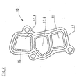
- FIG. 2 shows a view of the module-side flange 10.1 of the flange connection 10 according to FIG Figure 1 explains, the flange connection there comprises a total three channels. These three channels are the view on the flange 10.1 in Figure 1 again.
- the channel 12.1 is the crude oil channel through which of the internal combustion engine 7 contaminated oil to be filtered to the oil filter 2 is directed.
- the channel 12.2 performs the filtered in the filter 2 Lubricating oil again to the engine 7 and their lubrication points back.
- the channel 11 of the flange 10.1 is the combined gas and Oil channel for returning lubricating oil when emptying of the oil filter 2 at a filter cartridge replacement, for Returning the oil separator 3 from the crankcase ventilation gas separated oil and, in reverse Flow direction, for supplying the crankcase ventilation gas from the crankcase 71 of the internal combustion engine 7 to the oil separator 3 is used.
- a return of lubricating oil from the oil separator 3 may, depending on the design of the oil separator 3, either continuously during operation of the Internal combustion engine or discontinuously during breaks the internal combustion engine. If the oil return continuously, the oil flows from the oil separator 3 Coming towards the engine 7 and there in their sump 72. In countercurrent flows to the Crankcase vent gas through the same gas and oil passage 11 from the crankcase 71 to the oil separator 3.
- the module 1 according to Figure 1 the functions of the filtering Lubricating oil, emptying of the oil filter a filter cartridge replacement, the venting of the crankcase 71, the removal and return of oil from the Crankcase ventilation gas and the regulation of pressure in the crankcase 71 takes over, to fulfill all Functions in the area of the flange connection 10 only three Channels needed that need to be interconnected. In addition, there is only the external flow connection, to the connection 13.3 of the module 1 (see FIG 1) is to be connected.
- FIG 3 shows a second embodiment of the module 1, again in a schematic representation.
- the module 1 according to FIG 3 additionally an oil cooler 4, a lubricating oil filler neck 5.1 and a Schmierölbe spallanschluß 5.2 on.
- the oil cooler 4 is attached to the oil filter 2. Depending on Temperature of the lubricating oil becomes more or less large Proportion of the oil flowing through the oil filter 2 lubricating oil additionally passed through the oil cooler 4.
- the filter to be filtered and possibly also to be cooled oil passes through the crude oil channel 12.1 of the internal combustion engine 7 first in the Oil filter 2 and then if necessary in the oil cooler 4.
- the filtered and optionally additionally cooled oil passes from Oil filter 2 and oil cooler 4 through the clean oil channel 12.2 back to the internal combustion engine 7.
- Cooling water is used to cool the lubricating oil in the oil cooler 4 from the cooling water circuit of the engine 7.
- the integration of the oil cooler 4 in the module 1 thus only leads to an increase in the number the channels in the flange connection by two more channels, whereby the extra effort is kept within limits.
- For the supply of the lubricating oil to the oil cooler 4 and for the Derivation of the lubricating oil from the oil cooler 4 are only within of the module 1 between the oil filter 2 and the oil cooler 4 trained channels needed, not by the Flange connection 10 run.
- the oil cooler 4 still provided an oil drain 41.
- This oil drain 41 is used in addition, with an oil change also in the oil cooler 4 located Derive lubricating oil to complete as much as possible Replacing the lubricating oil to ensure an oil change.
- the opening of the oil drain 41 can be done manually or automatically effected by a filter cartridge change become.
- the oil drain 41 is within the module 1 with the combined gas and oil channel 11 connected. This serves here the combined gas and oil channel 11 for another Function, namely the emptying of the oil cooler 4 of Lubricating oil without this additional feature an increase the number of channels in the flange 10 to Episode has.
- the lubricating oil filler neck 5.1 serves as needed Refilling of lubricating oil and for filling the internal combustion engine with lubricating oil during an oil change.
- the lubricating oil filler neck 5.1 is in module 1 with the combined Gas and oil channel 11 connected.
- Next module 1 has the Filling nozzle or filling connection 5.2, for the first time Filling the engine 7 with lubricating oil serves and also in the combined gas and oil channel (11) opens. This is in the module 1 according to FIG 3 of the combined gas and oil channel 11 for two more Functions on the already explained in Figure 1 Functions used.
- the integration of the lubricating oil filler neck 5.1 and the filling nozzle or filling connection 5.2 in the module 1 lead here so also not to increase the number of channels within the flange connection 10th
- FIG. 4 shows a possible embodiment of the module side Flange 10.1 of the module 1 according to Figure 3 in a view. As can be seen from Figure 4, are in the flange 10.1 a total of five channels provided with corresponding Channels of the internal combustion engine 7 after manufacture the flange connection 10 correspond.
- the channel 12.1 is the crude oil channel through which to be filtered and, depending on the temperature, to be cooled lubricating oil for Oil filter 2 and possibly to the oil cooler 4 is feasible.
- the channel 12.2 in the flange 10.1 is the clean oil channel, through the filtered and possibly cooled lubricating oil from the oil filter 2 and oil cooler 4 returned to the engine 7 becomes.
- the channel 11 is the combined gas and oil channel, the fulfilled several functions.
- On one side is the Combined gas and oil channel 11 of the return of Lubricating oil from the oil filter 2 and the oil cooler 4 at a Filter insert change or oil change to the internal combustion engine 7, for returning the oil separator 3 from the crankcase ventilation gas separated oil to the internal combustion engine 7 and for the supply of an oil change through the lubricating oil filler 5.1 fresh filled Lubricating oil to the engine 7.
- In the other Direction serves the combined gas and oil channel 11 to Discharge of crankcase ventilation gas from the crankcase 71 of the internal combustion engine 7 to the oil separator.
- the two further channels 14.1 and 14.2 are cooling water channels, the cooling water from the engine 7 to Oil cooler 4 and the oil cooler 4 to the engine 7 to lead.
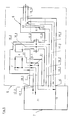
- FIG. 5 of the drawing shows a schematic representation a third embodiment of the module 1, wherein the module 1 here next to an oil filter 2 and an oil cooler 4 a the Coolant flow influencing actuator component 6 includes.
- the oil filter 2 receives from the internal combustion engine 7 via the oil channel 12.1 to be filtered oil. That in the oil filter 2 filtered oil returns via the clean oil channel 12.2 to the engine 7. Depending on the temperature of the oil filter 2 flowing oil is a more or less large Proportion thereof passed through the oil cooler 4 and therein by means Cooling water cooled.
- the oil cooler 4 is also here Assigned oil filter 2, so that the oil cooler 43 for his Oil supply and discharge via the two oil channels 12.1 and 12.2 no additional channels in the area of Flange connection 10 required.
- Cooling water passes from the engine 7 via a first cooling water passage 14.1 to the oil cooler 4; the end the cooling water exiting the oil cooler 4 flows over the second cooling water channel 14.2 back to the internal combustion engine, each through the flange 10 therethrough.
- Control element component 6 comprises in the illustrated Example two control elements, namely a thermostatic valve 61 and an adjustable flow divider 62nd
- the thermostatic valve 61 serves to from the internal combustion engine 7 coming cooling water depending on its temperature either by a small cooling circuit bypassing one cooling the cooling water, not in the drawing shown radiator directly to the engine 7 attributed or in a large cooling circuit below Flow through the radiator cooling the cooling water conduct.
- a small cooling circuit bypassing one cooling the cooling water, not in the drawing shown radiator directly to the engine 7 attributed or in a large cooling circuit below Flow through the radiator cooling the cooling water conduct.
- an internal cooling water channel 14.6 provided within of the module 1 in the second cooling water channel 14.2 opens, which in turn the cooling water to the engine 7 leads.
- the thermostatic valve When the cooling water temperature is high, the thermostatic valve conducts 61 the cooling water in the large cooling circuit and through the cooler for the cooling water, as mentioned above, for this purpose in the module 1 another cooling water channel 14.5 is provided to one outside the flange connection 10 lying connection of the module 1 leads. To the Connection end of this cooling water channel 14.5 is one to Cooler for the cooling water leading cooling water line connectable.
- crankcase breather and the dedicated oil separation and pressure control are in the module 1 according to Figure 5 is not integrated, but it is quite possible These functions also in the module 1 according to Figure 5 included.
- Other channels in the area of the flange connection 10 would not be needed because of the crankcase breather the channel 11 can be used, which already exists in module 1 according to FIG. 5 is. This requires the flange connection 10 for the module 1 according to Figure 5 or for the crankcase ventilation supplemented version only seven channels, what Given the variety of features a low Number is.
- FIG. 6 shows a view of the module side Connecting flange 10.1 of the module 1 according to FIG 5.
- Wie previously mentioned requires the flange connection with the Flange 10.1 here a total of seven channels.
- the crude oil channel 12. 1 which is that of the internal combustion engine coming, to be filtered and, if necessary, to cooling lubricating oil to the oil filter 2 and the oil cooler 4 passes.
- the clean oil channel 12.2 Underneath is the clean oil channel 12.2, which is the filtered one and, if necessary, cooled lubricating oil to the internal combustion engine 7 returns.
- a first cooling water channel 14.1 of the internal combustion engine coming cooling water to the oil cooler 4 leads.
- Under the channel 14.1 is the second cooling water channel 14.2.
- This channel 14.2 serves to return all cooling water streams from the module 1 to the internal combustion engine. 7
- Cooling water channels 14.3 and 14.4 At the bottom of the module-side flange 10.1 are two more Cooling water channels 14.3 and 14.4, the cooling water off various areas of the engine 7 to the module 1 lead.
- the cooling water channel 14.3 leads in the process Cooling water from the cylinder head of the engine. 7 This comes off while the channel 14.4 carries cooling water the area of the crankcase of the internal combustion engine. 7 comes.
- the two cooling water channels 14.3, 14.4 parts of the so-called "split-cooling" cooling system This cooling system allows a targeted and in particular different, demand-dependent cooling on the one hand of Area of the cylinder head and on the other hand the area the crankcase 71 of the internal combustion engine. 7
- a one-piece profile seal 16 each in a suitably shaped, preferably angegossene groove 17 is inserted.
- the flange can also be designed absolutely flat and with a flat gasket with matching openings be sealed against the engine 7.
Landscapes
- Engineering & Computer Science (AREA)
- Mechanical Engineering (AREA)
- General Engineering & Computer Science (AREA)
- Lubrication Details And Ventilation Of Internal Combustion Engines (AREA)
- Lubrication Of Internal Combustion Engines (AREA)
Abstract
Description
- Figur 1
- ein erstes Modul zusammen mit einer Brennkraftmaschine in einer stark schematisierten Darstellung,
- Figur 2
- das Modul aus Figur 1 in einer Ansicht auf seinen Verbindungsflansch,
- Figur 3
- ein zweites Modul zusammen mit einer Brennkraftmaschine, ebenfalls in schematischer Darstellung,
- Figur 4
- das Modul aus Figur 3 in Ansicht auf seinen Verbindungsflansch,
- Figur 5
- ein drittes Modul zusammen mit einer Brennkraftmaschine, wieder in schematischer Darstellung, und
- Figur 6
- das Modul aus Figur 5 in Ansicht auf seinen Verbindungsflansch.
Claims (17)
- Modul (1) für eine Brennkraftmaschine (7), das als bauliche Einheit aus zumindest einem Ölfilter (2) für das Schmieröl der Brennkraftmaschine (7) und einem Ölabscheider (3) für das Kurbelgehäuseentlüftungsgas der Brennkraftmaschine (7) ausgebildet ist und das als Ganzes mittels einer Flanschverbindung (10) unter Herstellung von Strömungsverbindungen an die Brennkraftmaschine (7) angeflanscht ist, wobei ein Ölkanal (12.1) für zu filterndes Öl von der Brennkraftmaschine (7) zum Ölfilter (2) und ein Ölkanal (12.2) für gefiltertes Öl vom Ölfilter (2) zur Brennkraftmaschine (7) führt, wobei ein Entlüftungskanal (13.1) für Kurbelgehäuseentlüftungsgas vom Kurbelgehäuse (71) der Brennkraftmaschine (7) zum Ölabscheider (3) führt und wobei ein Ölrücklaufkanal (13.2) für abgeschiedenes Öl vom Ölabscheider (3) zum Kurbelgehäuse (71) der Brennkraftmaschine (7) führt,
dadurch gekennzeichnet,daß im Modul (1) für eine Entleerung des Ölfilters (2) bei einem Filtereinsatzwechsel ein Entleerungskanal (21) vorgesehen ist, der durch die Flanschverbindung (10) mit dem Kurbelgehäuse (71) der Brennkraftmaschine (7) verbunden ist, unddaß der Entleerungskanal (21), der Entlüftungskanal (13.1) und der Ölrücklaufkanal (13.2) in der Flanschverbindung (10) und zumindest über einen Teil ihrer Länge im Modul (1) zu einem einzigen, kombinierten Gas- und Ölkanal (11) zusammengefaßt sind. - Modul nach Anspruch 1, dadurch gekennzeichnet, daß das Modul (1) einen Ölkühler (4) zur Kühlung des Schmieröls der Brennkraftmaschine (7) mittels deren Kühlwassers umfaßt, daß der Ölkühler (4) einen bei einem Öl- und/oder Filtereinsatzwechsel freigebbaren Ölablaß (41) aufweist und daß der Ölablaß (41) in den kombinierten Gas- und Ölkanal (11) mündet.
- Modul nach Anspruch 2, dadurch gekennzeichnet, daß das Modul (1) je einen Kühlwasser von der Brennkraftmaschine (7) zum Ölkühler (4) und Kühlwasser vom Ölkühler (4) zur Brennkraftmaschine (7) führenden, durch die Flanschverbindung (10) verlaufenden Kühlwasserkanal (14.1, 14.2) umfaßt.
- Modul nach einem der vorhergehenden Ansprüche , dadurch gekennzeichnet, daß das Modul (1) einen Schmieröleinfüllstutzen (5.1) für das Einfüllen von Schmieröl nach einem Ölwechsel und für ein bedarfsweises Nachfüllen von Schmieröl in die Brennkraftmaschine (7) umfaßt und daß der Schmieröleinfüllstutzen (5.1) in den kombinierten Gas- und Ölkanal (11) mündet.
- Modul nach einem der vorhergehenden Ansprüche , dadurch gekennzeichnet, daß das Modul (1) einen Befüllstutzen oder Befüllanschluß (5.2) für das erstmalige Befüllen der Brennkraftmaschine (7) mit Schmieröl umfaßt und daß der Befüllstutzen oder Befüllanschluß (5.2) in den kombinierten Gas- und Ölkanal (11) mündet.
- Modul nach einem der vorhergehenden Ansprüche , dadurch gekennzeichnet, daß das Modul (1) ein im Strömungsweg des im Ölabscheider (3) gereinigten Kurbelgehäuseentlüftungsgases liegendes Druckregelventil (30) zur Regelung des im Kurbelgehäuse (71) herrschenden Drucks umfaßt.
- Modul nach Anspruch 6, dadurch gekennzeichnet, daß das Druckregelventil (30) auf den Ölabscheider (3) aufgesetzt ist und einen Leitungsanschluß (13.3) für eine zu einem Ansaugtrakt der Brennkraftmaschine (7) führende Gasleitung für das im Ölabscheider (3) entölte Kurbelgehäuseentlüftungsgas aufweist.
- Modul (1) für eine Brennkraftmaschine (7), das als bauliche Einheit aus zumindest einem Ölfilter (2) für das Schmieröl der Brennkraftmaschine (7) und einem Ölkühler (4) für die Kühlung des Schmieröls mittels Kühlwassers der Brennkraftmaschine (7) ausgebildet ist und das als Ganzes mittels einer Flanschverbindung (10) unter Herstellung von Strömungsverbindungen an die Brennkraftmaschine (7) angeflanscht ist, wobei ein Ölkanal (12.1) für zu filterndes Öl von der Brennkraftmaschine (7) zum Ölfilter (2) und ein Ölkanal (12.2) für gefiltertes Öl vom Ölfilter (2) zur Brennkraftmaschine (7) führt, wobei ein erster Kühlwasserkanal (14.1) von der Brennkraftmaschine (7) zum Ölkühler (4) führt und wobei ein zweiter Kühlwasserkanal (14.2) vom Ölkühler (4) zur Brennkraftmaschine (7) führt,
dadurch gekennzeichnet,daß das Modul (1) mindestens ein das Kühlwasser auf verschiedene Strömungswege des Kühlwasserkreislaufs leitendes Stellelement (6) umfaßt unddaß im Modul (1) wenigstens ein weiterer Kühlwasserkanal (14.6) vorgesehen ist, der mit wenigstens einem der Kühlwasserkanäle (14.1, 14.2) verbunden ist und der Kühlwasser zum Stellelement (6) hin oder vom Stellelement (6) weg führt. - Modul nach Anspruch 8, dadurch gekennzeichnet, daß durch die Flanschverbindung (10) wenigstens ein weiterer, mit dem Stellelement (6) in Strömungsverbindung stehender Kühlwasserkanal (14.3, 14.4) verläuft.
- Modul nach Anspruch 8 oder 9, dadurch gekennzeichnet, daß das Stellelement (6) ein Thermostatventil (61) umfaßt, das das Kühlwasser abhängig von seiner Temperatur in einen kleinen Kühlkreislauf unter Umgehung eines das Kühlwasser kühlenden Kühlers oder in einen großen Kühlkreislauf unter Durchströmung des das Kühlwasser kühlenden Kühlers leitet.
- Modul nach einem der Ansprüche 8 bis 10, dadurch gekennzeichnet, daß das Stellelement (6) einen verstellbaren Strömungsteiler (62) umfaßt, der das Kühlwasser auf der Seite der Brennkraftmaschine (7) abhängig vom jeweiligen Kühlbedarf von deren Zylinderkopf und von deren Kurbelgehäuse (71) auf einen überwiegend den Zylinderkopf kühlenden Kühlwasserströmungsweg und einen überwiegend das Kurbelgehäuse (71) kühlenden Kühlwasserströmungsweg aufteilt.
- Modul nach einem der Ansprüche 8 bis 11, dadurch gekennzeichnet, daß an dem Modul (1) wenigstens ein Wasseranschluß (15.1, 15.2) für eine mit erwärmtem Kühlwasser betreibbare Heizung, insbesondere eine Kraftfahrzeug-Innenraumheizung, vorgesehen ist.
- Modul nach einem der vorhergehenden Ansprüche, dadurch gekennzeichnet, daß die die Flanschverbindung (10) durchlaufenden Kanäle (11, 12.1, 12.2, 14.1 - 14.4) gegeneinander und gegen die Umgebung durch axial dichtende Dichtmittel (16) abgedichtet sind.
- Modul nach Anspruch 13, dadurch gekennzeichnet, daß die Dichtmittel (16) der Flanschverbindung (10) an dem modulseitigen Flansch (10.1) angebracht sind.
- Modul nach Anspruch 14, dadurch gekennzeichnet, daß die Dichtmittel (16) durch eine einzige, einstückige Profildichtung gebildet sind.
- Modul nach einem der Ansprüche 13 bis 15, dadurch gekennzeichnet, daß das oder die Dichtmittel (16) in eine oder mehrere Aufnahmennuten (17) im modulseitigen Flansch (10.1) eingesetzt oder eingeklemmt oder eingeklebt oder einvulkanisiert ist/sind.
- Modul nach Anspruch 13 oder 14, dadurch gekennzeichnet, daß die Flanschverbindung (10) beidseitig ebenflächig ausgeführt ist und daß das Dichtmittel (16) eine einstückige Flachdichtung ist.
Priority Applications (1)
| Application Number | Priority Date | Filing Date | Title |
|---|---|---|---|
| EP11174890.1A EP2383443B1 (de) | 2003-07-14 | 2004-07-06 | Modul für eine Brennkraftmaschine |
Applications Claiming Priority (2)
| Application Number | Priority Date | Filing Date | Title |
|---|---|---|---|
| DE20310841U DE20310841U1 (de) | 2003-07-14 | 2003-07-14 | Modul für eine Brennkraftmaschine |
| DE20310841U | 2003-07-14 |
Related Child Applications (2)
| Application Number | Title | Priority Date | Filing Date |
|---|---|---|---|
| EP11174890.1A Division EP2383443B1 (de) | 2003-07-14 | 2004-07-06 | Modul für eine Brennkraftmaschine |
| EP11174890.1 Division-Into | 2011-07-21 |
Publications (3)
| Publication Number | Publication Date |
|---|---|
| EP1498582A2 true EP1498582A2 (de) | 2005-01-19 |
| EP1498582A3 EP1498582A3 (de) | 2010-04-21 |
| EP1498582B1 EP1498582B1 (de) | 2012-02-22 |
Family
ID=33462032
Family Applications (2)
| Application Number | Title | Priority Date | Filing Date |
|---|---|---|---|
| EP11174890.1A Expired - Lifetime EP2383443B1 (de) | 2003-07-14 | 2004-07-06 | Modul für eine Brennkraftmaschine |
| EP04015848A Expired - Lifetime EP1498582B1 (de) | 2003-07-14 | 2004-07-06 | Ölfilter und Ölabscheider-Modul für eine Brennkraftmaschine |
Family Applications Before (1)
| Application Number | Title | Priority Date | Filing Date |
|---|---|---|---|
| EP11174890.1A Expired - Lifetime EP2383443B1 (de) | 2003-07-14 | 2004-07-06 | Modul für eine Brennkraftmaschine |
Country Status (3)
| Country | Link |
|---|---|
| US (1) | US7069900B2 (de) |
| EP (2) | EP2383443B1 (de) |
| DE (1) | DE20310841U1 (de) |
Cited By (2)
| Publication number | Priority date | Publication date | Assignee | Title |
|---|---|---|---|---|
| EP2385277A1 (de) * | 2010-05-05 | 2011-11-09 | MAHLE International GmbH | Wärmetauscher |
| EP2808506A1 (de) * | 2013-05-28 | 2014-12-03 | Mahle International GmbH | Ölfilter/Ölmodul |
Families Citing this family (7)
| Publication number | Priority date | Publication date | Assignee | Title |
|---|---|---|---|---|
| DE202006007446U1 (de) * | 2006-05-10 | 2007-09-13 | Hengst Gmbh & Co.Kg | Ölmodul mit integriertem Kühlwasserkanal |
| JP5282774B2 (ja) | 2010-10-21 | 2013-09-04 | トヨタ自動車株式会社 | Pcvバルブの取付構造 |
| US8161953B1 (en) * | 2010-10-28 | 2012-04-24 | GM Global Technology Operations LLC | Adsorbent structures for removal of water and fuel contaminants in engine oil |
| DE102011115410A1 (de) | 2011-10-08 | 2013-04-11 | Daimler Ag | Anordnung eines Ölmoduls und einer Ölpumpe an einer Verbrennungskraftmaschine |
| CN103437851A (zh) * | 2013-08-09 | 2013-12-11 | 常州亚美柯机械设备有限公司 | 单缸柴油机强制润滑系统 |
| DE102015101410A1 (de) * | 2015-01-30 | 2016-08-04 | Volkswagen Ag | Brennkraftmaschine mit einem einen Ölkanal aufweisenden Ölrücklauf |
| CN109083714B (zh) * | 2018-08-15 | 2020-09-04 | 全椒县全动机械有限公司 | 一种内燃机曲轴油封回油结构 |
Citations (2)
| Publication number | Priority date | Publication date | Assignee | Title |
|---|---|---|---|---|
| DE20012736U1 (de) | 2000-07-22 | 2000-09-21 | Filterwerk Mann + Hummel GmbH, 71638 Ludwigsburg | Baugruppe für eine Brennkraftmaschine mit einem Ölfilter |
| EP0898060B1 (de) | 1997-08-20 | 2002-06-05 | Man Nutzfahrzeuge Ag | Ölmodul für Brennkraftmaschinen |
Family Cites Families (17)
| Publication number | Priority date | Publication date | Assignee | Title |
|---|---|---|---|---|
| US3223197A (en) * | 1960-06-08 | 1965-12-14 | Gen Motors Corp | Oil pump and cooler assembly for an internal combustion engine |
| DE3914759A1 (de) * | 1989-05-05 | 1990-11-08 | Mann & Hummel Filter | Einfuelloeffnung fuer das einfuellen von schmieroel in eine brennkraftmaschine |
| DE4017074A1 (de) * | 1990-05-26 | 1991-11-28 | Mann & Hummel Filter | Druckregelventil fuer die kurbelgehaeuseentlueftung an einer brennkraftmaschine |
| DE4212968C2 (de) * | 1992-04-18 | 1998-07-02 | Mann & Hummel Filter | Druckregelventil für die Kurbelgehäuseentlüftung einer Brennkraftmaschine |
| DE19606182A1 (de) * | 1996-02-20 | 1997-08-21 | Mann & Hummel Filter | Abtrennvorrichtung |
| DE19650033A1 (de) * | 1996-12-03 | 1998-06-04 | Mann & Hummel Filter | Baugruppe für eine Verbrennungskraftmaschine |
| DE19704209A1 (de) * | 1997-02-05 | 1998-08-06 | Mann & Hummel Filter | Baugruppe für eine Verbrennungskraftmaschine |
| DE19757759A1 (de) * | 1997-12-23 | 1999-06-24 | Mann & Hummel Filter | Filteranordnung |
| US6182616B1 (en) * | 1997-12-24 | 2001-02-06 | Isuzu Motors Limited | Cooling water circulating structure for engines |
| CA2401753A1 (en) * | 2000-02-29 | 2001-09-07 | Norbert Korenjak | Four stroke engine having power take off assembly |
| JP2002364328A (ja) * | 2000-09-20 | 2002-12-18 | Sanshin Ind Co Ltd | 小型船舶用エンジンのベンチレーションシステム |
| EP1195504B1 (de) * | 2000-10-03 | 2006-12-27 | Mazda Motor Corporation | Motorblockstruktur für eine Brennkraftmaschine |
| EP1211390B1 (de) * | 2000-12-01 | 2006-07-12 | Honda Giken Kogyo Kabushiki Kaisha | Trägergehäuse für Nebenaggregate für eine Brennkraftmaschine |
| JP2002256839A (ja) * | 2001-02-28 | 2002-09-11 | Sanshin Ind Co Ltd | 小型船舶のドライサンプ潤滑構造 |
| JP2002256836A (ja) * | 2001-02-28 | 2002-09-11 | Sanshin Ind Co Ltd | 小型船舶のオイルタンク冷却構造 |
| US6761142B2 (en) * | 2001-04-27 | 2004-07-13 | Yamaha Marine Kabushiki Kaisha | Oil pressure control for an outboard motor |
| DE10224224A1 (de) * | 2002-05-31 | 2003-12-11 | Mann & Hummel Filter | Filterelement, insbesondere zur Flüssigkeitsfilterung |
-
2003
- 2003-07-14 DE DE20310841U patent/DE20310841U1/de not_active Expired - Lifetime
-
2004
- 2004-07-06 EP EP11174890.1A patent/EP2383443B1/de not_active Expired - Lifetime
- 2004-07-06 EP EP04015848A patent/EP1498582B1/de not_active Expired - Lifetime
- 2004-07-13 US US10/889,862 patent/US7069900B2/en not_active Expired - Lifetime
Patent Citations (2)
| Publication number | Priority date | Publication date | Assignee | Title |
|---|---|---|---|---|
| EP0898060B1 (de) | 1997-08-20 | 2002-06-05 | Man Nutzfahrzeuge Ag | Ölmodul für Brennkraftmaschinen |
| DE20012736U1 (de) | 2000-07-22 | 2000-09-21 | Filterwerk Mann + Hummel GmbH, 71638 Ludwigsburg | Baugruppe für eine Brennkraftmaschine mit einem Ölfilter |
Cited By (2)
| Publication number | Priority date | Publication date | Assignee | Title |
|---|---|---|---|---|
| EP2385277A1 (de) * | 2010-05-05 | 2011-11-09 | MAHLE International GmbH | Wärmetauscher |
| EP2808506A1 (de) * | 2013-05-28 | 2014-12-03 | Mahle International GmbH | Ölfilter/Ölmodul |
Also Published As
| Publication number | Publication date |
|---|---|
| EP1498582A3 (de) | 2010-04-21 |
| EP1498582B1 (de) | 2012-02-22 |
| US20050011504A1 (en) | 2005-01-20 |
| EP2383443A1 (de) | 2011-11-02 |
| EP2383443B1 (de) | 2014-02-12 |
| US7069900B2 (en) | 2006-07-04 |
| DE20310841U1 (de) | 2004-11-25 |
Similar Documents
| Publication | Publication Date | Title |
|---|---|---|
| EP1751405B1 (de) | Ölwannenanordnung | |
| EP0925428B1 (de) | Baugruppe für eine verbrennungskraftmaschine | |
| EP2876274B1 (de) | Brennkraftmaschine | |
| DE10301564A1 (de) | Kühlkreislauf einer Brennkraftmaschine mit Niedertemperaturkühler | |
| EP0054792A2 (de) | Kühleinrichtung zur Kühlung einer Brennkraftmaschine und der Ladeluft | |
| EP4407150B1 (de) | Ölwanne, insbesondere ölfiltermodul, mit einem mehrteiligen gehäuse | |
| DE102004032653B4 (de) | Zylinderkopfstruktur eines Motors | |
| EP1498582A2 (de) | Ölfilter und Ölabscheider-Modul für eine Brennkraftmaschine | |
| DE20314687U1 (de) | Ölmodul für eine Brennkraftmaschine | |
| EP4407151A1 (de) | Ölwanne, insbesondere ölfiltermodul, mit einem mehrteiligen gehäuse | |
| EP0838577B1 (de) | Ölversorgungssystem für einen Kraftfahrzeugmotor | |
| EP1751411A1 (de) | Optimierte ölkühlung für eine brennkraftmaschine | |
| DE102013100017A1 (de) | Ölkühler | |
| DE102008021055B4 (de) | Verbrennungsmotor mit einem geschützten PCV System | |
| DE19701543A1 (de) | Kühlanordnung im Motorblock | |
| EP1337308B1 (de) | Aggregatemodul einer brennkraftmaschine | |
| DE102008060224B4 (de) | Öl-Abgas-Kühlmodul für eine Verbrennungskraftmaschine | |
| DE202005014632U1 (de) | Wärmetauscher mit Zwischenbauteil und Parallelventil | |
| DE102022104028A1 (de) | Verbrennungsmotor mit interner ölerwärmung von durchblasegas | |
| DE4328448A1 (de) | Wärmetauscher | |
| DE102012015784B4 (de) | Zylinderkopf für eine Verbrennungskraftmaschine sowie Verbrennungskraftmaschine mit einem solchen Zylinderkopf | |
| DE102004013763A1 (de) | Brennkraftmaschine mit Entlüftungssystem | |
| EP0999353A1 (de) | Guss-Maschinengehäuse für eine zwangsumlaufgekühlte Brennkraftmaschine mit Schmiersystem, insbesondere mit Zylindern in Reihenanordnung | |
| DE10218338B4 (de) | Brennkraftmaschine mit einer Ölwanne | |
| DE102006019020A1 (de) | Ölsammelraum eines Kraftfahrzeug-Verbrennungsmotors |
Legal Events
| Date | Code | Title | Description |
|---|---|---|---|
| PUAI | Public reference made under article 153(3) epc to a published international application that has entered the european phase |
Free format text: ORIGINAL CODE: 0009012 |
|
| AK | Designated contracting states |
Kind code of ref document: A2 Designated state(s): AT BE BG CH CY CZ DE DK EE ES FI FR GB GR HU IE IT LI LU MC NL PL PT RO SE SI SK TR |
|
| AX | Request for extension of the european patent |
Extension state: AL HR LT LV MK |
|
| PUAL | Search report despatched |
Free format text: ORIGINAL CODE: 0009013 |
|
| AK | Designated contracting states |
Kind code of ref document: A3 Designated state(s): AT BE BG CH CY CZ DE DK EE ES FI FR GB GR HU IE IT LI LU MC NL PL PT RO SE SI SK TR |
|
| AX | Request for extension of the european patent |
Extension state: AL HR LT LV MK |
|
| 17P | Request for examination filed |
Effective date: 20100907 |
|
| 17Q | First examination report despatched |
Effective date: 20101123 |
|
| AKX | Designation fees paid |
Designated state(s): CH DE ES FR GB IT LI |
|
| RBV | Designated contracting states (corrected) |
Designated state(s): DE ES FR GB IT SE |
|
| RIC1 | Information provided on ipc code assigned before grant |
Ipc: F01M 11/00 20060101ALI20110708BHEP Ipc: F01M 1/10 20060101AFI20110708BHEP Ipc: F01M 13/04 20060101ALI20110708BHEP |
|
| DAC | Divisional application: reference to earlier application (deleted) | ||
| GRAP | Despatch of communication of intention to grant a patent |
Free format text: ORIGINAL CODE: EPIDOSNIGR1 |
|
| GRAS | Grant fee paid |
Free format text: ORIGINAL CODE: EPIDOSNIGR3 |
|
| GRAA | (expected) grant |
Free format text: ORIGINAL CODE: 0009210 |
|
| AK | Designated contracting states |
Kind code of ref document: B1 Designated state(s): DE ES FR GB IT SE |
|
| REG | Reference to a national code |
Ref country code: GB Ref legal event code: FG4D Free format text: NOT ENGLISH |
|
| REG | Reference to a national code |
Ref country code: DE Ref legal event code: R081 Ref document number: 502004013308 Country of ref document: DE Owner name: HENGST SE, DE Free format text: FORMER OWNER: HENGST GMBH & CO. KG, 48147 MUENSTER, DE |
|
| REG | Reference to a national code |
Ref country code: DE Ref legal event code: R096 Ref document number: 502004013308 Country of ref document: DE Effective date: 20120419 |
|
| PG25 | Lapsed in a contracting state [announced via postgrant information from national office to epo] |
Ref country code: SE Free format text: LAPSE BECAUSE OF FAILURE TO SUBMIT A TRANSLATION OF THE DESCRIPTION OR TO PAY THE FEE WITHIN THE PRESCRIBED TIME-LIMIT Effective date: 20120222 |
|
| PLBE | No opposition filed within time limit |
Free format text: ORIGINAL CODE: 0009261 |
|
| STAA | Information on the status of an ep patent application or granted ep patent |
Free format text: STATUS: NO OPPOSITION FILED WITHIN TIME LIMIT |
|
| 26N | No opposition filed |
Effective date: 20121123 |
|
| REG | Reference to a national code |
Ref country code: DE Ref legal event code: R097 Ref document number: 502004013308 Country of ref document: DE Effective date: 20121123 |
|
| GBPC | Gb: european patent ceased through non-payment of renewal fee |
Effective date: 20120706 |
|
| PG25 | Lapsed in a contracting state [announced via postgrant information from national office to epo] |
Ref country code: GB Free format text: LAPSE BECAUSE OF NON-PAYMENT OF DUE FEES Effective date: 20120706 Ref country code: ES Free format text: LAPSE BECAUSE OF FAILURE TO SUBMIT A TRANSLATION OF THE DESCRIPTION OR TO PAY THE FEE WITHIN THE PRESCRIBED TIME-LIMIT Effective date: 20120602 |
|
| REG | Reference to a national code |
Ref country code: FR Ref legal event code: PLFP Year of fee payment: 13 |
|
| REG | Reference to a national code |
Ref country code: FR Ref legal event code: PLFP Year of fee payment: 14 |
|
| REG | Reference to a national code |
Ref country code: DE Ref legal event code: R082 Ref document number: 502004013308 Country of ref document: DE Representative=s name: SCHULZE HORN - FACHANWALTSKANZLEI FUER GEWERBL, DE Ref country code: DE Ref legal event code: R082 Ref document number: 502004013308 Country of ref document: DE Representative=s name: SCHULZE HORN & PARTNER GBR, DE Ref country code: DE Ref legal event code: R081 Ref document number: 502004013308 Country of ref document: DE Owner name: HENGST SE, DE Free format text: FORMER OWNER: HENGST GMBH & CO. KG, 48147 MUENSTER, DE Ref country code: DE Ref legal event code: R082 Ref document number: 502004013308 Country of ref document: DE Representative=s name: SCHULZE HORN & PARTNER GBR PATENT- UND RECHTSA, DE |
|
| REG | Reference to a national code |
Ref country code: DE Ref legal event code: R081 Ref document number: 502004013308 Country of ref document: DE Owner name: HENGST SE, DE Free format text: FORMER OWNER: HENGST SE CO. KG, 48147 MUENSTER, DE Ref country code: DE Ref legal event code: R082 Ref document number: 502004013308 Country of ref document: DE Representative=s name: SCHULZE HORN - FACHANWALTSKANZLEI FUER GEWERBL, DE Ref country code: DE Ref legal event code: R081 Ref document number: 502004013308 Country of ref document: DE Owner name: HENGST SE, DE Free format text: FORMER OWNER: HENGST SE & CO. KG, 48147 MUENSTER, DE Ref country code: DE Ref legal event code: R082 Ref document number: 502004013308 Country of ref document: DE Representative=s name: SCHULZE HORN & PARTNER GBR, DE Ref country code: DE Ref legal event code: R082 Ref document number: 502004013308 Country of ref document: DE Representative=s name: SCHULZE HORN & PARTNER GBR PATENT- UND RECHTSA, DE |
|
| REG | Reference to a national code |
Ref country code: FR Ref legal event code: PLFP Year of fee payment: 15 |
|
| PGFP | Annual fee paid to national office [announced via postgrant information from national office to epo] |
Ref country code: IT Payment date: 20230627 Year of fee payment: 20 |
|
| PGFP | Annual fee paid to national office [announced via postgrant information from national office to epo] |
Ref country code: FR Payment date: 20230703 Year of fee payment: 20 Ref country code: DE Payment date: 20230801 Year of fee payment: 20 |
|
| REG | Reference to a national code |
Ref country code: DE Ref legal event code: R082 Ref document number: 502004013308 Country of ref document: DE Representative=s name: SCHULZE HORN, KATHRIN, DE |
|
| REG | Reference to a national code |
Ref country code: DE Ref legal event code: R071 Ref document number: 502004013308 Country of ref document: DE |