EP1498964A1 - Batterieeinrichtung - Google Patents
Batterieeinrichtung Download PDFInfo
- Publication number
- EP1498964A1 EP1498964A1 EP03743529A EP03743529A EP1498964A1 EP 1498964 A1 EP1498964 A1 EP 1498964A1 EP 03743529 A EP03743529 A EP 03743529A EP 03743529 A EP03743529 A EP 03743529A EP 1498964 A1 EP1498964 A1 EP 1498964A1
- Authority
- EP
- European Patent Office
- Prior art keywords
- battery
- lid
- storage
- flame
- fixing
- Prior art date
- Legal status (The legal status is an assumption and is not a legal conclusion. Google has not performed a legal analysis and makes no representation as to the accuracy of the status listed.)
- Granted
Links
Images


Classifications
-
- H—ELECTRICITY
- H01—ELECTRIC ELEMENTS
- H01M—PROCESSES OR MEANS, e.g. BATTERIES, FOR THE DIRECT CONVERSION OF CHEMICAL ENERGY INTO ELECTRICAL ENERGY
- H01M50/00—Constructional details or processes of manufacture of the non-active parts of electrochemical cells other than fuel cells, e.g. hybrid cells
- H01M50/10—Primary casings; Jackets or wrappings
- H01M50/147—Lids or covers
-
- H—ELECTRICITY
- H01—ELECTRIC ELEMENTS
- H01M—PROCESSES OR MEANS, e.g. BATTERIES, FOR THE DIRECT CONVERSION OF CHEMICAL ENERGY INTO ELECTRICAL ENERGY
- H01M50/00—Constructional details or processes of manufacture of the non-active parts of electrochemical cells other than fuel cells, e.g. hybrid cells
- H01M50/50—Current conducting connections for cells or batteries
- H01M50/572—Means for preventing undesired use or discharge
- H01M50/584—Means for preventing undesired use or discharge for preventing incorrect connections inside or outside the batteries
- H01M50/59—Means for preventing undesired use or discharge for preventing incorrect connections inside or outside the batteries characterised by the protection means
- H01M50/591—Covers
-
- Y—GENERAL TAGGING OF NEW TECHNOLOGICAL DEVELOPMENTS; GENERAL TAGGING OF CROSS-SECTIONAL TECHNOLOGIES SPANNING OVER SEVERAL SECTIONS OF THE IPC; TECHNICAL SUBJECTS COVERED BY FORMER USPC CROSS-REFERENCE ART COLLECTIONS [XRACs] AND DIGESTS
- Y02—TECHNOLOGIES OR APPLICATIONS FOR MITIGATION OR ADAPTATION AGAINST CLIMATE CHANGE
- Y02E—REDUCTION OF GREENHOUSE GAS [GHG] EMISSIONS, RELATED TO ENERGY GENERATION, TRANSMISSION OR DISTRIBUTION
- Y02E60/00—Enabling technologies; Technologies with a potential or indirect contribution to GHG emissions mitigation
- Y02E60/10—Energy storage using batteries
Definitions
- the present invention relates to a battery apparatus used, for example, as a power source for a mobile phone unit or other electronic equipment, in which a battery unit containing an element of generating power is stored in a storage portion formed by overlapping a battery storage and a lid.
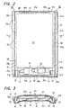
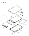
- a battery apparatus 1 shown in FIG. 8 includes a battery unit 2 having a power-generating element, a battery storage 3 having a storage portion 5 in which the battery unit 2 is stored, and a lid 4 to close the storage portion 5 of the battery storage 3.
- the battery apparatus 1 is used, for example, as a power source for a mobile phone unit, and the battery unit 2 has an arched-shape due to the limitation of the space to be stored in the mobile phone unit.
- the battery unit 2 for example, polymer secondary cell is employed.
- the battery storage 3 for storing the battery unit 2, and the lid 4 are formed of synthetic resin such as polycarbonate (PC).
- a step portion is circumferentially provided on the periphery of the battery storage 3 surrounding the storage portion 5.
- a corresponding step portion engaged with that step portion of the battery storage 3 is provided on the periphery of the lid 4.
- Two electrode terminals 2a, 2b are lead out from the battery unit 2 and are connected to a circuit substrate 6a of a control circuit 6 provided for controlling discharge, charge, and so on of the battery unit 2.
- a circuit substrate 6a of a control circuit 6 provided for controlling discharge, charge, and so on of the battery unit 2.
- Numeral 7 denotes an insulating board functioning as a partition to separate the battery unit 2 and the controlling circuit 6.
- numeral 8a denotes double-faced tape for fixing the battery unit 2 in the lid 4
- numeral 8b denotes a double-faced tape for fixing the battery unit 2 in the battery storage 3.
- the battery storage 3 and the lid 4 are both formed of synthetic resin, it is difficult to meet the demand of providing a thinner battery storage 3 and lid 4, and therefore there was a problem in which capacity of the power-generating element can not be increased in the case where the outside dimensions are unchanged.
- the battery storage 3 and the lid 4 are both formed of synthetic resin that has problems in pliability, strength, and the like, it is difficult to reduce the thickness of the battery storage 3 and the lid 4.
- FIG. 9 there has been provided a battery apparatus 10 with an improved structure.
- a battery storage 11 and a lid 12 are improved and no other constituents are modified. Accordingly, hereupon only the battery storage 11 and the lid 12 will be explained, and to other constituents the same numerals are given and the explanation thereof is omitted.
- the battery storage 11 of the battery apparatus 10 is composed of a flame 13 in which a large square opening 11a is provided on the lower surface portion thereof and a closing unit 14 which is integrally provided with the flame 13 to close the opening 11a.
- the lid 12 is composed of a flame 15 in which a large square opening 12a is provided on the upper surface portion thereof and a closing unit 16 which is integrally provided with the flame 15 to close the opening 12a. While the flames 13 and 15 are formed of synthetic resin, the closing units 14 and 16 are formed of metal, and by employing what is called insert molding the flames and closing units are integrally formed.
- a numeral 9a denotes a double-face tape also functioning as an insulating tape provided between the battery unit 2 and the lid 12.
- a numeral 9b denotes a double-face tape also functioning as an insulating tape provided between the battery unit 2 and the battery storage 11.
- the battery apparatus 10 which includes the battery storage 11 and the lid 12 having such structure, if the outside dimensions are identical and each member has the same strength, members formed of metal can be made extremely thinner compared to those formed of synthetic resin. Accordingly, with respect to the battery storage 11 and the lid 12, a capacity of the storage portion 5 can be made larger to the amount of decrease in the thickness of the closing units 14 and 16 which are formed of metal. Consequently, the thickness of the battery unit 2 can increase as much as the capacity of the storage portion 5 increases, thereby increasing the capacity of the battery unit 2 to obtain a larger amount of electricity.
- the present invention is made in light of the above problems and provides a battery apparatus, in which a lid that closes the end of an opening of a storage portion of a battery storage, or a closing unit that closes the bottom of the battery storage is formed to be capable of being engaged with the battery storage; means for fixing the lid to the battery storage or for fixing the closing unit to the lid is provided to firmly fix the lid to the battery storage, or to firmly fix the closing unit to the lid to be integrally formed, respectively, preventing each member from being separated; and a capacity of the storage portion is made as large as possible to increase the capacity of the battery unit and thus increase the amount of electricity.
- a battery apparatus includes: a battery unit which contains a power-generating element, a battery storage having a storage portion in which the battery unit is stored, and a lid which closes the end of an opening of the storage portion of the battery storage, wherein a first fixing means for enabling the lid to be engaged with the battery storage and for fixing the lid to the battery storage is provided.
- a battery apparatus 20 showing an embodiment of the present invention includes: a battery unit 21 in which a power-generating element is contained, a flame 22 having a storage portion 29 in which the battery unit 21 is stored, an upper case 23 that is a specific example of a lid which closes the upper surface, that is, a one surface side of the storage portion 29 of the flame 22, a lower case 24 that is a specific example of a closing unit which closes the lower surface, that is, the other surface side of the storage portion 29 of the flame 22, upper and lower insulating sheets 25 and 26, a control circuit 27, an insulating plate 28, and the likes.
- a nonaqueous electrolytic secondary battery (such as a polymer secondary battery, lithium ion secondary battery, or the like) can be applied.
- the battery unit 21 in which, for example, through a separating member formed of polymer film a positive electrode and a positive collector are lapped over a negative electrode and a negative collector to be contained in a covering member formed of a laminated film of aluminum foil and plastic, and in vacuum the periphery of the covering member is subjected to the thermal deposition to be sealed. From the covering member, an electrode terminal 21a connected to the positive collector and an electrode terminal 21b connected to the negative collector are lead out.
- the battery unit 21 has a rectangular-shaped plane, on a side in a longitudinal direction of which a U-shaped circuit storage portion 30 formed by utilizing a part of the covering member subjected to the thermal deposition is provided.
- a control circuit 27 is stored in a space divided by an insulating plate 28 formed of an insulative plastic sheet or the like.
- the control circuit 27 includes a circuit substrate 31 provided with a predetermined circuit pattern, and to the circuit substrate 31 the terminals 21a and 21b of positive and negative electrodes are connected. Further, on both the surfaces of the circuit substrate 31 various kinds of electronic components 32 are mounted so that the charge, discharge and so on of the battery unit 21 are controlled for the safety and to prevent irreversible breakdown of the electrodes caused by overcharge and over discharge.
- the flame 22 is formed of a flame-shaped member capable of completely containing the battery unit 21, in which the storage portion 29 is composed of a square-shaped opening provided through the top and bottom surfaces.
- the flame 22 includes long side portions 22a, 22b provided parallel to oppose each other, and short side portions 22c, 22d provided parallel to oppose each other extending in the direction intersecting the long sides.
- the flame 22 is shaped like an arch which is curved corresponding to the shape of the battery unit 21 with the upper surface thereof protruding convexly and the lower surface thereof being bent concavely.
- the upper case 23 is dome-shaped, whose upper surface is curved like an arch corresponding to the shape of the upper surface of the flame 22.
- the upper case 23 has an upper surface portion 23a that closes one end of the opening, which constitutes one surface of the storage portion 29 of the flame 22, and long side surface portions 23b, 23c and short side surface portions 23d, 23e that continue to the four sides of the upper surface portion 23a, respectively. Further, on respective side surface portions 23b to 23e of the upper case 23 an appropriate number of fixing pieces 33 are provided.
- each of the fixing pieces 33 there are provided four fixing pieces 33 on each of the long side surface portions 23b, 23c, one fixing piece 33 on one of the short side surface portions, that is, the short side surface portion 23d, and two fixing pieces 33 on the other short side surface portion 23e. Furthermore, in each of the fixing pieces 33 there is provided an oblong-shaped engaging hole 33a which represents a specific example of a concave portion.
- the lower case 24 has a convexly curved lower surface corresponding to the shape of the lower surface of the flame 22.
- the lower case 24 has a lower surface portion 24a that closes the other end of the opening, which constitutes another surface of the storage portion 29 of the flame 22, and long side surface portions 24b, 24c and short side surface portions 24d, 24e which continue to four sides of the lower surface portion 24a, respectively. Further, on respective side surface portions 24b to 24e of the lower case 24 an appropriate number of fixing pieces 34 are provided.
- each of the fixing pieces 34 there are provided three fixing pieces 34 on each of the long side surface portions 24b, 24c, two fixing pieces 34 are provided on one of the short side surface portions, that is, the short side surface portion 24d, and one fixing piece 34 on the other short side surface portion 24e of the lower case 24. Furthermore, in each of the fixing pieces 34 there is provided an oblong-shaped engaging hole 34a which represents a specific example of a concave portion.
- engaging hooks 35, 36 representing a specific example of a convex portion that each constitute first fixing means and second fixing means by being combined with the engaging hole 33a in the fixing piece 33 of the upper case 23 and being combined with the engaging hole 34a in the fixing piece 34 of the lower case 24, respectively, and peaked portions 37, 38 supporting the base portions of respective fixing pieces 33, 34 which are engaged with those engaging hooks 35, 36 are provided in number equal to that of the corresponding fixing pieces 33, 34.
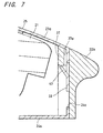
- the engaging hooks 35 are to fix the fixing pieces 33 of the upper case 23, and, as shown in FIG. 5, have a hook-shape in which the upper surface thereof is inclined corresponding to the upper fixing piece 33 that is inserted downward, and the lower surface thereof is plane.
- upper peaked portions 37 protruding like overhangs are each provided. Further, in each of the upper peaked portions 37 there is provided a slit 37a through which the upper fixing portion 33 is made to pass.
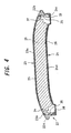
- the other engaging hooks 36 are to fix the fixing pieces 34 of the lower case 24, and, as shown in FIG. 4, have a hook-shape in which the lower surface thereof is inclined corresponding to the lower fixing piece 34 that is inserted upward, and the upper surface thereof is plane.
- lower peaked portions 38 of protruding edges are each provided.
- a slit 38a through which the lower fixing portion 34 is made to pass.
- the two long side portions 22a, 22b of the flame 22 there are provided four engaging hooks 35 and four peaked portions 37 corresponding to the fixing pieces 33 of the upper case 23, and three engaging hooks 36 and three peaked portions 38 corresponding to the fixing pieces 34 of the lower case 24.
- the short side portion 22c of the flame 22 there are provided one engaging hook 35 and one peaked portion 37 corresponding to the fixing piece 33 of the upper case 23, and two engaging hooks 36 and two peaked portions 38 corresponding to the fixing pieces 34 of the lower case 24 are provided.
- the upper engaging hooks 35 and lower engaging hooks 36 are set at an approximately equal height, and are alternately disposed. Accordingly, when the upper case 23 and lower case 24 are attached to the flame 22 including such upper and lower engaging hooks 35, 37, the upper fixing pieces 33 and the lower fixing pieces 34 are joined to be engaged such that the pieces are meshed with each other, and disposed alternately.
- a pair of supporting portions 40, 41 which hold both ends of the circuit substrate 31 of the above-mentioned control circuit 27.
- the pair of supporting portions 40, 41 is engaged with a pair of holes bored on the circuit substrate 31 to support the both ends of the circuit substrate 31, so that the circuit substrate 31 is disposed to divide the circuit storage portion 30 of the battery unit 21 into upper and lower parts.
- an appropriate space is provided above and under the circuit substrate 31, so that on both surfaces of the circuit substrate 31 desired electronic components can be mounted.
- polycarbonate PC
- metal and other materials metal and other materials than plastics.
- stainless steel such as SUS304 or the like
- SUS304 stainless steel
- the insulating sheet 25 is provided between the battery unit 21 and the upper case 23 to ensure the insulation; and though the sheet is preferably made of polyester, other sheet-shaped insulating members such as other plastics, paper, and other materials can also be applied.
- the other insulating sheet 26 provided between the battery unit 21 and the lower case 24 has a function of not only ensuring the insulation but also fixing the battery unit 21. Therefore, on a surface of the lower insulating sheet 26 an adhesive layer is provided by, for example, coating the surface with adhesive to bond the adhesive layer with the battery unit 21. By means of the lower insulating sheet 26, the movement of the battery unit 21 can be restrained or prevented, and the battery unit is prevented from being lopsided.
- the battery apparatus 20 having the above structure can be manufactured, for example, through the following assembly process.
- the lower case 24 is attached to the flame 22.
- the lower surface of the flame 22 is opposed to the side of the lower case 24, from which the fixing pieces 34 are protruded, and a number of fixing pieces 34 are inserted upward into the storage portion 29 composed of the opening of the flame 22.
- each of the fixing pieces 34 is individually inserted and pressed into the slit 38a of the corresponding lower peaked portion 38 provided on the lower surface side of the flame 22.
- the tip thereof slides along a slope portion to climb over the lower engaging hook 36, and the lower engaging hook 36 enters the engaging hole 34a provided in each fixing piece 34.
- the engaging holes 34a of the lower fixing pieces 34 and the lower engaging hooks 36 of the flame 22 are engaged to form the second fixing means, through which the lower case 24 is fixed to the flame 22 and assembled.
- the battery unit 21 In the storage portion 29 of the flame 22, whose lower surface is closed by the lower case 24, there is stored the battery unit 21 to which the control circuit 27 and the insulating plate 28 are attached in advance.
- the lower insulating sheet 26 is bonded with the lower surface of the battery unit 21 to be integrally provided.
- the upper insulating sheet 25 is disposed on the upper surface of the battery unit 21.
- the upper case 23 is attached to the flame 22.
- the storage portion 29 of the flame 22 is opposed to the side of the upper case 23, from which the fixing pieces 33 are protruded.
- each of the fixing pieces 33 of the upper case 23 is individually inserted and pressed into the slit 37a of the corresponding upper peaked portion 37 provided on the upper surface side of the flame 22.
- the tip thereof slides along a slope portion to climb over the upper engaging hook 35, and the upper engaging hook 35 enters the engaging hole 33a provided in each fixing piece 33.
- the battery apparatus 20 After the positions of the upper case 23 and the lower case 24 are determined with respect to the flame 22, respective cases 23 and 24 are pressed toward the flame 22 side, so that the upper case 23 and the lower case 24 can be fixed to the flame 22 easily and rapidly. Further, when the upper case 23 and the lower case 24 are once attached, the first and second fixing means, through which both the cases are respectively fixed, are formed between each of the cases and the flame 22, and since each of the engaging hooks 35 and 36 serves as a stopper for preventing falling-off, there is no possibility that the upper case 23 and the lower case 24 disengage from the flame 22, thereby enabling the original assembled state to be maintained.
- the upper case 23 and the lower case 24 are formed of metal, particularly formed of stainless steel, while the strength of each case is maintained to a predetermined degree, the thickness thereof can be made as thin as possible. Therefore, a capacity of the storage portion 29 can be increased to the extent of the decrease in thickness of each case. Accordingly, a capacity of the battery unit 21 can be increased corresponding to the increase in the capacity of the storage portion 29, whereby the amount of electricity such as generated, charged and the like of the battery unit 21 can be increased.
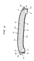
- FIGS. 6 and 7 show another embodiment of the above-described first and second fixing means.
- upper and lower engaging hooks 35, 36, and the engaging holes 33a, 34a provided in the upper and lower fixing pieces 33, 34 of the above-described first embodiment are not provided, in each of the fixing pieces 33, 34 of the upper case 23 and the lower case 24 there are provided projections 43, 44 representing a second embodiment of the convex portions constituting one member of the fixing means, and the concave portions, to which the above projections are engaged, are provided by using the inside surface of the peaked portions 37, 38.
- the projections 43, 44 are respectively formed by cutting parts of the fixing pieces 33, 34 to the inside.
- the upper fixing piece 33 of the upper case 23 there is provided a cut-out portion in which three other sides than the end side are cut out in a U-shape, and the free end of the cut-out portion is bent toward the inside, thereby forming each of the projections 43, 44 having an appropriate resilience. Since the other structure is the same as the above-described embodiment, the same numerals are given to the corresponding parts and the explanation thereof will be omitted.
- the second embodiment of the battery apparatus 20 having such structure can be manufactured similarly to the first embodiment. Specifically, since the upper case 23 and the lower case 24 are sequentially assembled with respect to the flame 22 in a similar order, the assembly can be executed easily and rapidly. In this embodiment, for example, when the fixing piece 33 of the upper case 23 (the lower case 24 in similar manner) is inserted through the slit 37a of the upper peaked portion 37 of the flame 22, the projection 43 (the projection 44 in similar manner) is resiliently deformed with its own resilience and returns to the original shape after passing through the upper peaked portion 37.
- the tip of the projection 43 is engaged with the inside surface of the upper peaked portion 37. Accordingly, the upper case 23 is firmly fixed to the flame 22 and is prevented from being disengaged. Similar effectiveness to that of the above-described first embodiment is obtained when the upper case 23 and lower case 24 having such fixing means are employed, and therefore the amount of electricity of the battery unit 21 can be increased.
- the present invention is not limited to the aforementioned embodiments, and in the above embodiments, though, for example, there was explained an example in which the second battery having a cross section of the arched shape is employed, needless to say batteries having other cross sections such as a rectangular shape, an elliptic (oval shape) shape and other appropriate shapes can be applied.
- batteries having other cross sections such as a rectangular shape, an elliptic (oval shape) shape and other appropriate shapes can be applied.
- the battery unit an example of a polymer secondary battery in which power-generating element is contained and sealed in an aluminum laminated film is applied to the above embodiment, a secondary battery in other shapes and structures can also be applied.
- the flame can also be formed with metal similar to the upper and lower cases, and can be formed such that the fixing pieces are also provided on the flame with a convex portion being provided in one of the fixing pieces and with a concave portion being provided in the other fixing pieces.
- the flame 22 and the lower case 24 are formed of separate members and the lower case 24 is integrally assembled with the flame 22, it is also possible to originally provide the flame and lower case using a single member and only the upper case is subsequently attached.
- the present invention can be variously modified without departing from the gist thereof.
- the battery apparatus since the battery apparatus according to the present invention has the structure in which a lid is engaged with a battery storage to cover a storage portion storing a battery unit and a first fixing means is provided to fix the both, the lid is fixed to the battery storage through the first fixing means, thereby enabling the battery storage and the lid to be reliably integrated and firmly fixed to each other without being separated, only employing the simple structure.
- the battery storage is formed of the flame and a closing unit, and a second fixing means is provided to fix the both, thereby enabling the flame and the closing unit to be reliably integrated and firmly fixed to each other without being separated, only employing the simple structure.
- the first fixing means composed of a convex portion on one side and a concave portion on the other side of fixing pieces each provided on the battery storage and the lid
- the second fixing means composed of the convex portion on one side and the concave portion on the other side of the fixing pieces each provided on the flame and the closing unit
- the battery storage or the lid is formed of synthetic resin or metal; the lid or the closing unit is formed of metal; and the thickness thereof is made thinner, the capacity of the storage portion can be increased to the extent of the reduction in the thickness and thus the capacity of the battery unit is made to increase corresponding to the increase in capacity of the storage portion, whereby the amount of electricity can be increased. Accordingly, compared to a conventional battery apparatus, there can be provided the battery apparatus capable of generating larger amount of electricity regardless of the outside dimension thereof.
Landscapes
- Chemical & Material Sciences (AREA)
- Chemical Kinetics & Catalysis (AREA)
- Electrochemistry (AREA)
- General Chemical & Material Sciences (AREA)
- Battery Mounting, Suspending (AREA)
Applications Claiming Priority (3)
| Application Number | Priority Date | Filing Date | Title |
|---|---|---|---|
| JP2002060694 | 2002-03-06 | ||
| JP2002060694A JP2003257389A (ja) | 2002-03-06 | 2002-03-06 | 電池装置 |
| PCT/JP2003/002351 WO2003075374A1 (fr) | 2002-03-06 | 2003-02-28 | Dispositif a batterie |
Publications (3)
| Publication Number | Publication Date |
|---|---|
| EP1498964A1 true EP1498964A1 (de) | 2005-01-19 |
| EP1498964A4 EP1498964A4 (de) | 2009-09-23 |
| EP1498964B1 EP1498964B1 (de) | 2012-04-04 |
Family
ID=27784813
Family Applications (1)
| Application Number | Title | Priority Date | Filing Date |
|---|---|---|---|
| EP03743529A Expired - Lifetime EP1498964B1 (de) | 2002-03-06 | 2003-02-28 | Batterieeinrichtung |
Country Status (5)
| Country | Link |
|---|---|
| US (1) | US7361428B2 (de) |
| EP (1) | EP1498964B1 (de) |
| JP (1) | JP2003257389A (de) |
| CN (1) | CN1306631C (de) |
| WO (1) | WO2003075374A1 (de) |
Cited By (9)
| Publication number | Priority date | Publication date | Assignee | Title |
|---|---|---|---|---|
| EP1995804A1 (de) * | 2007-05-25 | 2008-11-26 | Samsung SDI Co., Ltd. | Batteriepack |
| EP2207223A1 (de) * | 2009-01-13 | 2010-07-14 | Samsung SDI Co., Ltd. | Batteriepack |
| US8329331B2 (en) | 2007-11-12 | 2012-12-11 | Samsung Sdi Co., Ltd. | Terminal connector assembly and battery module having the same |
| US8404380B2 (en) | 2007-01-25 | 2013-03-26 | Samsung Sdi Co., Ltd. | Inter-connector between unit cells and serial cell |
| EP2775549A1 (de) * | 2013-03-06 | 2014-09-10 | Samsung SDI Co., Ltd. | Wiederaufladbares Batteriepaket |
| US8835034B2 (en) | 2008-10-08 | 2014-09-16 | Samsung Sdi Co., Ltd. | Rechargeable battery and battery module |
| EP2911219A1 (de) * | 2014-02-21 | 2015-08-26 | Samsung SDI Co., Ltd. | Batteriepack |
| EP2884558A3 (de) * | 2013-12-12 | 2015-09-16 | Samsung SDI Co., Ltd. | Wiederaufladbare Batterie |
| EP4329052A4 (de) * | 2022-06-23 | 2024-08-21 | Ningde Amperex Technology Limited | Gehäuse, bogenförmige batterie und elektrische vorrichtung |
Families Citing this family (42)
| Publication number | Priority date | Publication date | Assignee | Title |
|---|---|---|---|---|
| CN2757341Y (zh) * | 2004-11-27 | 2006-02-08 | 深圳富泰宏精密工业有限公司 | 电池盖结构 |
| US8778529B2 (en) * | 2004-11-29 | 2014-07-15 | Samsung Sdi Co., Ltd. | Lithium secondary battery |
| KR100857021B1 (ko) * | 2004-12-10 | 2008-09-05 | 주식회사 엘지화학 | 결착식 전지팩 |
| CN2777908Y (zh) * | 2004-12-30 | 2006-05-03 | 深圳富泰宏精密工业有限公司 | 便携式电子装置电池盖结构 |
| US20100216012A1 (en) * | 2005-04-26 | 2010-08-26 | Samsung Sdi Co., Ltd. | Lithium rechargeable battery |
| JP2007273359A (ja) * | 2006-03-31 | 2007-10-18 | Sanyo Electric Co Ltd | 密閉型電池 |
| KR101075902B1 (ko) * | 2007-01-06 | 2011-10-25 | 주식회사 엘지화학 | 탄력적인 연결부재를 포함하고 있는 전지팩 케이스 |
| KR100846972B1 (ko) * | 2007-01-10 | 2008-07-17 | 삼성에스디아이 주식회사 | 이차전지의 외장케이스 및 그를 이용한 이차전지 |
| JP5130717B2 (ja) * | 2007-01-10 | 2013-01-30 | 日本電気株式会社 | 電子部品収納構造及び該構造を備えた電子機器 |
| KR100954589B1 (ko) * | 2007-02-07 | 2010-04-26 | 삼성에스디아이 주식회사 | 보호회로 조립체 및 이를 구비한 배터리 팩 |
| TW200835028A (en) * | 2007-02-15 | 2008-08-16 | Simplo Technology Co Ltd | Closed packing process of extra thin battery and product thereof |
| JP2008251455A (ja) * | 2007-03-30 | 2008-10-16 | Kyocera Corp | 小型電子機器 |
| TWI339910B (en) * | 2007-04-23 | 2011-04-01 | Simplo Technology Co Ltd | An encapsulation process and a product of a special thin battery |
| KR100882914B1 (ko) | 2007-05-21 | 2009-02-10 | 삼성에스디아이 주식회사 | 배터리 팩 |
| ATE477598T1 (de) * | 2007-05-30 | 2010-08-15 | Simplo Technology Co Ltd | Verpackungsverfahren für dünne batterien |
| JP4513897B2 (ja) * | 2008-06-02 | 2010-07-28 | 株式会社カシオ日立モバイルコミュニケーションズ | 携帯電話端末 |
| KR100983144B1 (ko) * | 2008-06-05 | 2010-09-20 | 삼성에스디아이 주식회사 | 배터리 팩 |
| CN101673847B (zh) * | 2008-09-09 | 2012-05-02 | 比亚迪股份有限公司 | 一种锂离子电池和该锂离子电池的制造方法 |
| KR101002511B1 (ko) | 2008-09-19 | 2010-12-17 | 삼성에스디아이 주식회사 | 폴리머 전지팩 |
| US8334063B2 (en) | 2008-09-22 | 2012-12-18 | Samsung Sdi Co., Ltd. | Secondary battery |
| KR101036062B1 (ko) * | 2008-12-11 | 2011-05-19 | 삼성에스디아이 주식회사 | 이차 전지 |
| JP5449835B2 (ja) * | 2009-04-06 | 2014-03-19 | 三洋電機株式会社 | パック電池 |
| DE102009035489A1 (de) * | 2009-07-31 | 2011-02-03 | Daimler Ag | Einzelzelle für eine Batterie |
| KR101093294B1 (ko) * | 2009-10-26 | 2011-12-14 | 삼성에스디아이 주식회사 | 홀더 케이스 및 이를 구비하는 배터리 팩 |
| KR101146675B1 (ko) * | 2010-08-09 | 2012-05-23 | 삼성에스디아이 주식회사 | 배터리 팩 |
| WO2013125748A1 (ko) * | 2012-02-23 | 2013-08-29 | 세방전지(주) | 음각구조를 이용한 전지셀 케이스 |
| JP5944203B2 (ja) * | 2012-04-09 | 2016-07-05 | 三洋電機株式会社 | 電池パック |
| KR102052588B1 (ko) * | 2013-08-13 | 2019-12-05 | 삼성에스디아이 주식회사 | 이차전지 팩 |
| US9354660B2 (en) * | 2013-08-19 | 2016-05-31 | Kabushiki Kaisha Toshiba | Electronic device |
| KR20150037380A (ko) * | 2013-09-30 | 2015-04-08 | 주식회사 엘지화학 | 곡면 구조의 전지셀 수납용 트레이 |
| WO2015046751A1 (ko) * | 2013-09-30 | 2015-04-02 | 주식회사 엘지화학 | 곡면 구조의 전지팩 |
| KR102221803B1 (ko) | 2014-01-20 | 2021-03-02 | 삼성에스디아이 주식회사 | 전지 팩 |
| KR102234288B1 (ko) * | 2014-04-16 | 2021-03-31 | 삼성에스디아이 주식회사 | 전지 팩 |
| KR102234293B1 (ko) | 2014-04-16 | 2021-03-31 | 삼성에스디아이 주식회사 | 전지 팩 |
| TWI599703B (zh) * | 2014-06-24 | 2017-09-21 | 克緹斯國際股份有限公司 | 具有電池之板材 |
| CN112151847B (zh) * | 2015-01-23 | 2024-12-03 | 株式会社半导体能源研究所 | 二次电池及二次电池的制造方法 |
| WO2018133822A1 (zh) * | 2017-01-18 | 2018-07-26 | 苏州宝时得电动工具有限公司 | 自移动设备及其自动工作方法 |
| US12548847B2 (en) * | 2022-12-07 | 2026-02-10 | Samsung Sdi Co., Ltd. | Rechargeable battery module |
| EP4693584A1 (de) * | 2023-03-31 | 2026-02-11 | Ningde Amperex Technology Limited | Sekundärbatterie und elektronische vorrichtung |
| WO2025182520A1 (ja) * | 2024-02-26 | 2025-09-04 | パナソニックIpマネジメント株式会社 | 電池パック |
| WO2025182486A1 (ja) * | 2024-02-26 | 2025-09-04 | パナソニックIpマネジメント株式会社 | 電池パック |
| CN118472532A (zh) * | 2024-05-20 | 2024-08-09 | 中山普纳斯能源科技有限公司 | 电池组件及应用其的软包电池 |
Family Cites Families (14)
| Publication number | Priority date | Publication date | Assignee | Title |
|---|---|---|---|---|
| JPH06349459A (ja) * | 1993-06-08 | 1994-12-22 | Yuasa Corp | 密閉形鉛蓄電池 |
| JPH09121392A (ja) * | 1995-10-26 | 1997-05-06 | Matsushita Electric Ind Co Ltd | 送信器 |
| JPH11111249A (ja) * | 1997-10-03 | 1999-04-23 | Fuji Elelctrochem Co Ltd | 電池パック用ケース |
| JPH11176400A (ja) * | 1997-10-06 | 1999-07-02 | Japan Storage Battery Co Ltd | 電池ケース |
| ES2263189T3 (es) * | 1997-11-05 | 2006-12-01 | Philips Consumer Communications France | Unidad de bateria y dispositivo portatil alimentado por bateria que incluye dicha unidad de bateria. |
| US6068946A (en) * | 1998-08-02 | 2000-05-30 | Motorola, Inc. | Dual cover battery casing |
| WO2000016416A1 (en) | 1998-09-11 | 2000-03-23 | Matsushita Electric Industrial Co., Ltd. | Battery pack |
| JP3710644B2 (ja) | 1999-05-31 | 2005-10-26 | 松下電器産業株式会社 | 電池パック |
| EP1071147A1 (de) | 1999-07-19 | 2001-01-24 | Toshiba Battery Co., Ltd. | Batteriesatz |
| JP2001093495A (ja) | 1999-07-19 | 2001-04-06 | Toshiba Battery Co Ltd | 電池パック |
| WO2001037353A1 (en) * | 1999-11-15 | 2001-05-25 | Eveready Battery Company, Inc. | Durable high density power supply |
| JP2001307703A (ja) * | 2000-04-19 | 2001-11-02 | Kenwood Corp | 電池パック |
| JP4938166B2 (ja) | 2000-10-06 | 2012-05-23 | 三洋電機株式会社 | 電池パック |
| JP2002124233A (ja) * | 2000-10-16 | 2002-04-26 | Hitachi Maxell Ltd | 電池パック |
-
2002
- 2002-03-06 JP JP2002060694A patent/JP2003257389A/ja active Pending
-
2003
- 2003-02-28 CN CNB038052652A patent/CN1306631C/zh not_active Expired - Fee Related
- 2003-02-28 WO PCT/JP2003/002351 patent/WO2003075374A1/ja not_active Ceased
- 2003-02-28 US US10/506,621 patent/US7361428B2/en not_active Expired - Fee Related
- 2003-02-28 EP EP03743529A patent/EP1498964B1/de not_active Expired - Lifetime
Cited By (15)
| Publication number | Priority date | Publication date | Assignee | Title |
|---|---|---|---|---|
| US8404380B2 (en) | 2007-01-25 | 2013-03-26 | Samsung Sdi Co., Ltd. | Inter-connector between unit cells and serial cell |
| EP1995804A1 (de) * | 2007-05-25 | 2008-11-26 | Samsung SDI Co., Ltd. | Batteriepack |
| US8895178B2 (en) | 2007-05-25 | 2014-11-25 | Samsung Sdi Co., Ltd. | Battery pack |
| US8053103B2 (en) | 2007-05-25 | 2011-11-08 | Samsung Sdi Co., Ltd. | Battery pack |
| US8329331B2 (en) | 2007-11-12 | 2012-12-11 | Samsung Sdi Co., Ltd. | Terminal connector assembly and battery module having the same |
| US8835034B2 (en) | 2008-10-08 | 2014-09-16 | Samsung Sdi Co., Ltd. | Rechargeable battery and battery module |
| EP2207223A1 (de) * | 2009-01-13 | 2010-07-14 | Samsung SDI Co., Ltd. | Batteriepack |
| US9184425B2 (en) | 2009-01-13 | 2015-11-10 | Samsung Sdi Co., Ltd. | Battery pack |
| EP2775549A1 (de) * | 2013-03-06 | 2014-09-10 | Samsung SDI Co., Ltd. | Wiederaufladbares Batteriepaket |
| US9123933B2 (en) | 2013-03-06 | 2015-09-01 | Samsung Sdi Co., Ltd. | Rechargeable battery pack |
| EP2884558A3 (de) * | 2013-12-12 | 2015-09-16 | Samsung SDI Co., Ltd. | Wiederaufladbare Batterie |
| US9847515B2 (en) | 2013-12-12 | 2017-12-19 | Samsung Sdi Co., Ltd. | Rechargeable battery |
| EP2911219A1 (de) * | 2014-02-21 | 2015-08-26 | Samsung SDI Co., Ltd. | Batteriepack |
| US9825266B2 (en) | 2014-02-21 | 2017-11-21 | Samsung Sdi Co., Ltd. | Battery pack |
| EP4329052A4 (de) * | 2022-06-23 | 2024-08-21 | Ningde Amperex Technology Limited | Gehäuse, bogenförmige batterie und elektrische vorrichtung |
Also Published As
| Publication number | Publication date |
|---|---|
| JP2003257389A (ja) | 2003-09-12 |
| WO2003075374A1 (fr) | 2003-09-12 |
| CN1306631C (zh) | 2007-03-21 |
| EP1498964B1 (de) | 2012-04-04 |
| CN1639886A (zh) | 2005-07-13 |
| EP1498964A4 (de) | 2009-09-23 |
| US7361428B2 (en) | 2008-04-22 |
| US20050130030A1 (en) | 2005-06-16 |
Similar Documents
| Publication | Publication Date | Title |
|---|---|---|
| EP1498964A1 (de) | Batterieeinrichtung | |
| KR100884945B1 (ko) | 파우치형 이차전지 | |
| US10014556B2 (en) | Battery cell including stepped structure | |
| US9209493B2 (en) | Battery pack | |
| US12597675B2 (en) | Pouch-type battery cell including venting member and battery pack including the same | |
| JP2008305774A (ja) | バッテリパック | |
| JP7473367B2 (ja) | 電池パック | |
| JP3863856B2 (ja) | 電池パック | |
| US20030027041A1 (en) | Prismatic sealed battery module | |
| JP2018107054A (ja) | 角形二次電池 | |
| KR101045862B1 (ko) | 조립 및 분해가 용이한 전지팩 케이스 및 이를 포함하는전지팩 | |
| JP2001093496A (ja) | 扁平電池の収容ケース及びそれを用いた電池パック | |
| KR101082870B1 (ko) | 금속 소재의 전지팩 케이스 | |
| KR100813812B1 (ko) | 프레임 부재에 체결홈이 형성되어 있는 전지팩 | |
| KR20190096730A (ko) | 전지 팩 | |
| JP2003323876A (ja) | 電池パック | |
| KR20200077304A (ko) | 비대칭 형태의 오목부를 포함하는 파우치형 전지케이스 | |
| JP7473368B2 (ja) | 電池パック | |
| KR101846486B1 (ko) | 일체형 양극리드 및 음극리드를 포함하는 전지셀 | |
| JP5154054B2 (ja) | 電池容器及び電池 | |
| KR20160109425A (ko) | 배터리 팩 | |
| JP2005347104A (ja) | コイン形電池 | |
| JP2001307693A (ja) | 電池パック | |
| JP2007227319A (ja) | 電池パック | |
| JP2004014217A (ja) | 非水電解質二次電池 |
Legal Events
| Date | Code | Title | Description |
|---|---|---|---|
| PUAI | Public reference made under article 153(3) epc to a published international application that has entered the european phase |
Free format text: ORIGINAL CODE: 0009012 |
|
| 17P | Request for examination filed |
Effective date: 20040908 |
|
| AK | Designated contracting states |
Kind code of ref document: A1 Designated state(s): AT BE BG CH CY CZ DE DK EE ES FI FR GB GR HU IE IT LI LU MC NL PT SE SI SK TR |
|
| A4 | Supplementary search report drawn up and despatched |
Effective date: 20090826 |
|
| 17Q | First examination report despatched |
Effective date: 20091203 |
|
| 17Q | First examination report despatched |
Effective date: 20100408 |
|
| GRAP | Despatch of communication of intention to grant a patent |
Free format text: ORIGINAL CODE: EPIDOSNIGR1 |
|
| RIN1 | Information on inventor provided before grant (corrected) |
Inventor name: ISHIKAWA, YUHO,C/O SONY CORPORATION Inventor name: AKASAWA, HIDETOSHI,C/O SONY CORPORATION Inventor name: WATANABE, KOUJI,C/O SONY FUKUSHIMA CORPORATION |
|
| GRAS | Grant fee paid |
Free format text: ORIGINAL CODE: EPIDOSNIGR3 |
|
| RIN1 | Information on inventor provided before grant (corrected) |
Inventor name: WATANABE, KOUJI,C/O SONY FUKUSHIMA CORPORATION Inventor name: ISHIKAWA, YUHO,C/O SONY CORPORATION Inventor name: AKASAWA, HIDETOSHI,C/O SONY CORPORATION |
|
| RAP1 | Party data changed (applicant data changed or rights of an application transferred) |
Owner name: SONY CORPORATION |
|
| GRAA | (expected) grant |
Free format text: ORIGINAL CODE: 0009210 |
|
| AK | Designated contracting states |
Kind code of ref document: B1 Designated state(s): DE FR GB |
|
| REG | Reference to a national code |
Ref country code: GB Ref legal event code: FG4D |
|
| REG | Reference to a national code |
Ref country code: DE Ref legal event code: R096 Ref document number: 60340489 Country of ref document: DE Effective date: 20120531 |
|
| PLBE | No opposition filed within time limit |
Free format text: ORIGINAL CODE: 0009261 |
|
| STAA | Information on the status of an ep patent application or granted ep patent |
Free format text: STATUS: NO OPPOSITION FILED WITHIN TIME LIMIT |
|
| 26N | No opposition filed |
Effective date: 20130107 |
|
| REG | Reference to a national code |
Ref country code: DE Ref legal event code: R097 Ref document number: 60340489 Country of ref document: DE Effective date: 20130107 |
|
| GBPC | Gb: european patent ceased through non-payment of renewal fee |
Effective date: 20130228 |
|
| REG | Reference to a national code |
Ref country code: FR Ref legal event code: ST Effective date: 20131031 |
|
| REG | Reference to a national code |
Ref country code: DE Ref legal event code: R119 Ref document number: 60340489 Country of ref document: DE Effective date: 20130903 |
|
| PG25 | Lapsed in a contracting state [announced via postgrant information from national office to epo] |
Ref country code: FR Free format text: LAPSE BECAUSE OF NON-PAYMENT OF DUE FEES Effective date: 20130228 Ref country code: DE Free format text: LAPSE BECAUSE OF NON-PAYMENT OF DUE FEES Effective date: 20130903 Ref country code: GB Free format text: LAPSE BECAUSE OF NON-PAYMENT OF DUE FEES Effective date: 20130228 |