EP1501141A1 - Separator for fuel cell - Google Patents
Separator for fuel cell Download PDFInfo
- Publication number
- EP1501141A1 EP1501141A1 EP03723165A EP03723165A EP1501141A1 EP 1501141 A1 EP1501141 A1 EP 1501141A1 EP 03723165 A EP03723165 A EP 03723165A EP 03723165 A EP03723165 A EP 03723165A EP 1501141 A1 EP1501141 A1 EP 1501141A1
- Authority
- EP
- European Patent Office
- Prior art keywords
- fuel cell
- separator
- peripheral part
- passages
- elastic member
- Prior art date
- Legal status (The legal status is an assumption and is not a legal conclusion. Google has not performed a legal analysis and makes no representation as to the accuracy of the status listed.)
- Granted
Links
Images


Classifications
-
- H—ELECTRICITY
- H01—ELECTRIC ELEMENTS
- H01M—PROCESSES OR MEANS, e.g. BATTERIES, FOR THE DIRECT CONVERSION OF CHEMICAL ENERGY INTO ELECTRICAL ENERGY
- H01M8/00—Fuel cells; Manufacture thereof
- H01M8/02—Details
-
- H—ELECTRICITY
- H01—ELECTRIC ELEMENTS
- H01M—PROCESSES OR MEANS, e.g. BATTERIES, FOR THE DIRECT CONVERSION OF CHEMICAL ENERGY INTO ELECTRICAL ENERGY
- H01M8/00—Fuel cells; Manufacture thereof
- H01M8/02—Details
- H01M8/0202—Collectors; Separators, e.g. bipolar separators; Interconnectors
- H01M8/0247—Collectors; Separators, e.g. bipolar separators; Interconnectors characterised by the form
- H01M8/0254—Collectors; Separators, e.g. bipolar separators; Interconnectors characterised by the form corrugated or undulated
-
- H—ELECTRICITY
- H01—ELECTRIC ELEMENTS
- H01M—PROCESSES OR MEANS, e.g. BATTERIES, FOR THE DIRECT CONVERSION OF CHEMICAL ENERGY INTO ELECTRICAL ENERGY
- H01M8/00—Fuel cells; Manufacture thereof
- H01M8/02—Details
- H01M8/0271—Sealing or supporting means around electrodes, matrices or membranes
-
- H—ELECTRICITY
- H01—ELECTRIC ELEMENTS
- H01M—PROCESSES OR MEANS, e.g. BATTERIES, FOR THE DIRECT CONVERSION OF CHEMICAL ENERGY INTO ELECTRICAL ENERGY
- H01M8/00—Fuel cells; Manufacture thereof
- H01M8/10—Fuel cells with solid electrolytes
-
- H—ELECTRICITY
- H01—ELECTRIC ELEMENTS
- H01M—PROCESSES OR MEANS, e.g. BATTERIES, FOR THE DIRECT CONVERSION OF CHEMICAL ENERGY INTO ELECTRICAL ENERGY
- H01M8/00—Fuel cells; Manufacture thereof
- H01M8/02—Details
- H01M8/0202—Collectors; Separators, e.g. bipolar separators; Interconnectors
- H01M8/0204—Non-porous and characterised by the material
- H01M8/0206—Metals or alloys
-
- Y—GENERAL TAGGING OF NEW TECHNOLOGICAL DEVELOPMENTS; GENERAL TAGGING OF CROSS-SECTIONAL TECHNOLOGIES SPANNING OVER SEVERAL SECTIONS OF THE IPC; TECHNICAL SUBJECTS COVERED BY FORMER USPC CROSS-REFERENCE ART COLLECTIONS [XRACs] AND DIGESTS
- Y02—TECHNOLOGIES OR APPLICATIONS FOR MITIGATION OR ADAPTATION AGAINST CLIMATE CHANGE
- Y02E—REDUCTION OF GREENHOUSE GAS [GHG] EMISSIONS, RELATED TO ENERGY GENERATION, TRANSMISSION OR DISTRIBUTION
- Y02E60/00—Enabling technologies; Technologies with a potential or indirect contribution to GHG emissions mitigation
- Y02E60/30—Hydrogen technology
- Y02E60/50—Fuel cells
Definitions
- This invention relates to a fuel cell separator having multiple passages provided in a peripheral part of the separator and used to guide reaction gases and a reaction product.
- Fig. 10 shows a fuel cell of related art.
- This fuel cell 100 is made by disposing a negative electrode 102 and a positive electrode 103 respectively on the upper face side and the lower face side of an electrolyte membrane 101, placing a separator 105 on the upper side of the negative electrode 102 and sandwiching the peripheral vicinity of the electrolyte membrane 101 and the peripheral vicinity of the upper side separator 105 with an upper side gasket 106, and placing a separator 105 on the lower side of the positive electrode 103 and sandwiching the peripheral vicinity of the electrolyte membrane 101 and the peripheral vicinity of the lower side separator 105 with a lower side gasket 106.
- hydrogen gas is supplied through multiple hydrogen gas passages 107 as shown by the arrow a.
- the hydrogen gas in the hydrogen gas passages 107 is guided toward a central part 105a of the upper side separator 105 as shown with an arrow.
- Oxygen gas is supplied through multiple oxygen gas passages 108 as shown by the arrow b.
- the oxygen gas in the oxygen gas passages 108 is guided toward the central part 105a of the lower side separator 105 as shown with an arrow.
- product water (H 2 O) is produced from the hydrogen molecules (H 2 ) and the oxygen molecules (O 2 ), and this product water flows through multiple product water passages 109 as shown by the arrow c.
- the upper side gasket 106 is sandwiched in the gap between the peripheral vicinity of the electrolyte membrane 101 and the peripheral vicinity of the upper side separator 105, and the lower side gasket 106 is sandwiched in the gap between the peripheral vicinity of the electrolyte membrane 101 and the peripheral vicinity of the lower side separator 105.
- the fuel cell 100 it is desirable for the fuel cell 100 to be compact, and it is necessary for the upper and lower gaskets 106 to be made thin. Consequently, handling of the upper and lower gaskets 106 has been difficult, it has taken time for the upper and lower gaskets 106 to be disposed in the proper positions, and this has constituted a hindrance to raising fuel cell productivity.
- a separator 113 is inserted in a gap between a fixed die 111 and a moving die 112 and a cavity 114 is formed by the fixed die 111 and the moving die 112, and by the cavity 114 being filled with molten resin as shown with an arrow, a seal 115 is formed on a peripheral part 113a of the separator 113.
- the seal 115 being formed around the peripheral part 113a of the separator 113 like this, the upper and lower gaskets 106 shown in Fig. 10 can be made unnecessary. Therefore, in the manufacture of the fuel cell, it is possible to dispense with a step of incorporating the upper and lower gaskets 106.
- the invention provides, in a fuel cell separator having provided in a peripheral part gas passages for guiding reaction gases and reaction product passages for guiding a reaction product, reaction gases being guided from the gas passages to a central part and reaction product produced at the central part being guided to the reaction product passage, a fuel cell separator characterized in that the central part is made a metal member and the peripheral part is made a resin member and this resin member is connected to the metal member by an elastic member.
- peripheral part of the separator is made a resin member and the peripheral part is connected to the central part by an elastic member.
- the peripheral part of the separator being connected to the central part by an elastic member, the separator can be manufactured relatively easily. Therefore, the yield in the production of separators can be raised.
- the resin member has a different thermal expansion coefficient from the metal member, if the resin member constituting the peripheral part were to be connected to the metal member constituting the central part directly, there would be a risk of the central part deforming or the peripheral part suffering fatigue failure due to differential thermal expansion between the peripheral part and the central part.
- the peripheral part is connected to the central part by way of an elastic member.
- a projecting central seal part surrounding the central part is provided on the elastic member. That is, when a projecting central seal part surrounding the central part is provided on the elastic member, in the assembling of the separator, it is not necessary to incorporate a central part gasket for surrounding the central part. Consequently, in the assembling of a fuel cell, it is possible to dispense with the trouble of incorporating a central part gasket.
- the central part in the assembling of the separator to a fuel cell, the central part can be surely sealed by the projecting central seal part. As a result, gases guided to the central part can be surely guided to the proper position, and reaction product produced in the central part can be surely guided to the proper position.
- projecting passage seal parts severally surrounding the gas passages and the reaction product passages are provided on the peripheral part.
- projecting passage seal parts severally surrounding the gas passages and the reaction product passages are provided on the peripheral part like this, in the assembling of the separator, it is not necessary to incorporate passage gaskets for surrounding the gas passages and the reaction product passages.
- passage gaskets for surrounding the gas passages and the reaction product passages.
- the gas passages and reaction product passages can be surely sealed with the projecting passage seal parts.
- the elastic member and the central seal part are formed integrally from a rubber material.
- these members can be formed simultaneously. Consequently, the elastic member and the central seal part can be formed easily in a short time.
- a fuel cell 10 according to the invention shown in Fig. 1 has a structure wherein a negative electrode 15 and a positive electrode 16 are respectively disposed on the upper face 11a side and the lower face 11b (see Fig. 2) side of an electrolyte membrane 11 and an upper side separator 20 (fuel cell separator) is superposed on the negative electrode 15 and a lower side separator 20 is superposed on the positive electrode 16.
- the fuel cell 10 made by stacking the electrolyte membrane 11, the negative electrode 15, the positive electrode 16 and the upper and lower separators 20, 20 is referred to as a cell, and multiple cells arrayed in a stack are referred to as a fuel cell; however, in this specification, to facilitate understanding, the cell will be called a fuel cell.
- the electrolyte membrane 11 has multiple hydrogen gas passages (gas passages) 12 for guiding hydrogen gas (a reaction gas), multiple oxygen gas passages (gas passages) 13 for guiding oxygen gas (a reaction gas), and multiple product water passages (reaction product passages) 14 for guiding product water (a reaction product).
- gas passages 12 for guiding hydrogen gas (a reaction gas)
- oxygen gas passages 13 for guiding oxygen gas (a reaction gas)
- product water passages reaction product passages
- the negative electrode 15 and the positive electrode 16 are each formed somewhat smaller than the electrolyte membrane 11. The peripheries of the negative electrode 15 and the positive electrode 16 are positioned inward of the hydrogen gas passages 12, the oxygen gas passages 13 and the product water passages 14.
- the separators 20 each have a metal central part 22, a resin peripheral part 30 around that, and an elastic member 40 connecting the central part 22 and the peripheral part 30 together.
- the peripheral part 30 has multiple hydrogen gas passages (gas passages) 31 for guiding hydrogen gas, multiple oxygen gas passages (gas passages) 32 for guiding oxygen gas, and multiple product water passages (reaction product passages) 33 for guiding product water.
- peripheral part 30 of each of the separators 20 being made a resin member and this peripheral part 30 being provided with hydrogen gas passages 31, oxygen gas passages 32 and product water passages 33, corrosion resistance of the hydrogen gas passages 31, the oxygen gas passages 32 and the product water passages 33 with respect to the gases and product water is ensured.
- the multiple hydrogen gas passages 31 and oxygen gas passages 32 formed in the peripheral part 30 of each separator 20 are formed in locations such that they are aligned with the multiple hydrogen gas passages 12 and oxygen gas passages 13 formed in the peripheral parts of the electrolyte membrane 11 when the fuel cell 10 is assembled.
- the multiple product water passages 33 formed in each separator 20 are formed in locations such that they are aligned with the multiple product water passages 14 formed in the electrolyte membrane 11 when the fuel cell 10 is assembled.
- product water H 2 O
- oxygen molecules O 2
- Fig. 2 shows the fuel cell separators 20 each made up of a metal central part 22, a resin peripheral part 30 and an elastic member 40.
- the central part 22 is a metal member and is a stainless steel plate having multiple flow passages 23 for guiding hydrogen gas and multiple flow passages 24 for guiding oxygen gas formed in its upper face 22a and its lower face 22b, and passages for guiding product water (not shown), and having had an anti-corrosion plating treatment carried out on its upper face 22a and lower face 22b.
- This central part 22 has primer-treated parts 25a, 25b, on which a primer treatment has been carried out, on its upper and lower faces around its edge part 22c, and has multiple first openings 26 provided at a predetermined spacing in the primer-treated parts 25a, 25b.
- the shape of the first openings 26 may be round holes, slots or rectangular, and there is no restriction on this. The reasons for providing the primer-treated parts 25a, 25b and the first openings 26 will be discussed later.
- the peripheral part 30 is a frame formed somewhat larger than the central part 22, and is a frame made of an engineering plastic with the multiple hydrogen gas passages 31, oxygen gas passages 32 and product water passages 33 (the passages 32, 33 are shown in Fig. 1) formed in this frame.
- multiple projecting passage seal parts 34 are provided along the respective edges of the hydrogen gas passages 31, the oxygen gas passages 32 and the product water passages 33 so as to individually surround the hydrogen gas passages 31, oxygen gas passages 32 and product water passages 33.
- multiple passage recesses 35 are provided along the respective edges of the hydrogen gas passages 31, the oxygen gas passages 32 and the product water passages 33 so as to individually surround the hydrogen gas passages 31, oxygen gas passages 32 and product water passages 33.
- the shape of the second openings 38 may be round holes, slots or rectangular, and there is no restriction on this. The reason for providing the second openings 38 will be discussed later.
- a gap S can be provided between the inner edge 30c of the peripheral part 30 and the edge 22c of the central part 22.
- the projecting passage seal parts 34 are formed so that when the fuel cell 10 is assembled, they are pressed against the passage recesses 35 of the separator 20 disposed above on the other side of the passages 12, 13 and 14 (see Fig. 1 for passages 13, 14) of the electrolyte membrane 11.
- the projecting passage seal parts 34 are provided so as to surround the hydrogen gas passages 31, the oxygen gas passages 32 and the product water passages 33 individually, in the assembly of the separator 20 to the fuel cell 10 it is not necessary to incorporate a passage gasket for surrounding the hydrogen gas passages 31, oxygen gas passages 32 and product water passages 33. Consequently, in assembling the fuel cell 10, it is possible to dispense with the trouble of incorporating passage gaskets.
- the projecting passage seal parts 34 are provided so as to surround the hydrogen gas passages 31, the oxygen gas passages 32 and the product water passages 33 individually, in the assembling of the separator 20 to the fuel cell 10, the projecting passage seal parts 34 can be pressed against the passage recesses 35 to surely seal the hydrogen gas passages 31, oxygen gas passages 32 and product water passages 33.
- the elastic member 40 is a connecting member made of silicone rubber which covers the primer-treated parts 25a, 25b of the central part 22 and the thin part 37 of the peripheral part 30, fills the first openings 26 and the second openings 38, and has on its upper face 40a a projecting central seal part 41 (see also Fig. 1) surrounding the central part 22.
- the elastic member 40 is provided with a projecting central seal part 41 surrounding the central part 22, when the fuel cell 10 is assembled, it is not necessary to incorporate a central gasket for surrounding the central part 22. As a result, in the assembling of the fuel cell 20, it is possible to dispense with the trouble of incorporating a central gasket.
- the projecting central seal part 41 can be pushed against the electrolyte membrane 11 to surely seal the central part 22.
- the hydrogen gas and oxygen gas guided to the central part 22 can be surely guided to the proper positions, and product water produced in the central part 22 can be surely guided to the proper position.
- the elastic member 40 and the central seal part 41 are formed integrally from silicone rubber (rubber material), the elastic member 40 and the central seal part 41 can be formed simultaneously. Consequently, the elastic member 40 and the central seal part 41 can be formed easily in a short time.
- first anchors 42 can be provided in the first openings 26 and second anchors 43 can be provided in the second openings 38.
- the engineering plastic of the peripheral part 30 has a different thermal expansion coefficient from the stainless steel of the central part 22, if the peripheral part 30 were to be connected to the central part 22 directly, it is likely that the central part 22 would deform or the peripheral part 30 would suffer fatigue failure due to differential thermal expansion between the peripheral part 30 and the central part 22.
- peripheral part 30 being connected to the central part 22 by way of the elastic member 40, differential thermal expansion between the peripheral part 30 and the central part 22 is absorbed.
- deformation of the central part 22 and fatigue failure of the peripheral part 30 due to differential thermal expansion between the peripheral part 30 and the central part 22 can be prevented.
- the projecting central seal part 41 is formed so as to be pressed against the electrolyte membrane 11 when the fuel cell 10 is assembled.
- Fig. 3A and Fig. 3B are a sectional view on the line 3A-3A and a sectional view on the line 3B-3B in Fig. 2.
- Fig. 3A shows the first openings 26 formed as slots, as an example, and first anchors 42 provided in the first openings 26 by these slots being filled with the elastic member 40.
- Fig. 3B shows the second openings 38 formed as slots, as an example, and second anchors 43 provided in the second openings 38 by these slots being filled with the elastic member 40.
- Fig. 4A AND Fig. 4B are first action views illustrating steps in the manufacture of a fuel cell separator according to the invention.
- a primer treatment is carried out on the upper and lower faces 22a, 22b. That is, silicone rubber is baked onto the upper and lower faces 22a, 22b at a temperature of 150°C to form primer-treated parts 25a, 25b.
- Fig. 4B the central part 22 with the primer-treated parts 25a, 25b is placed on a fixed die 51 on a turntable 50 as shown by the arrow [1]. Then, by the turntable 50 being turned as shown by the arrow [2], the fixed die 51 is brought to rest under a first movable die 52.
- the fixed die 51 and the first movable die 52 form a peripheral part mold for injection-molding the peripheral part 30 of the separator 20 shown in Fig. 1 and Fig. 2.
- Fig. 5A and Fig. 5B are second action views showing a process for manufacturing a fuel cell separator according to the invention.
- a molten resin 57 of an engineering plastic is injected into a peripheral part cavity 58 as shown by the arrows [4].
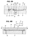
- Fig. 6A and Fig. 6B are third action views showing a process for manufacturing a fuel cell separator according to the invention, Fig. 6A being an enlarged view of the part 6B in Fig. 5B.
- the peripheral part cavity 58 is filled with the molten resin 57.
- a core 59 is made to project slightly into the peripheral part cavity 58 from the fixed die 51
- projections 52a of the first movable die 52 are made to project as far as the core 59
- shoulder parts 52b are made to project slightly into the peripheral part cavity 58, whereby a thin part 37 is formed and second openings 38 are formed in the thin part 37.
- Fig. 7A and Fig. 7B are fourth action views showing a process for manufacturing a fuel cell separator according to the invention.
- the fixed die 51 and the second movable die 61 form an elastic member mold for injection-molding the elastic member 40 of the separator 20 shown in Fig. 1 and Fig. 2.
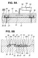
- Fig. 8A and Fig. 8B are fifth action views showing a process for manufacturing a fuel cell separator according to the invention.
- an elastic member cavity 67 is formed by the fixed die 51 and the second movable die 61, and seal cavities 68 are formed by the second movable die 61 and the peripheral part 30.
- the central part 22 is a metal member, because the primer-treated parts 25a, 25b have been provided at the periphery of the central part 22, the elastic member 40 can be adhered well to the central part 22.
- first anchors 42 and second anchors 43 can be formed in the first openings 26 and the second openings 38 respectively.
- the central part 22 can be prevented from detaching from the elastic member 40, and the peripheral part 30 can be prevented from detaching from the elastic member 40.
- the passage seal parts 34 and the central seal part 41 can be molded from silicone rubber (rubber material) simultaneously.
- the elastic member 40, the passage seal parts 34 and the central seal part 41 can be formed easily in a short time.
- Fig. 9A and Fig. 9B are sixth action views showing a process for manufacturing a fuel cell separator according to the invention.
- Fig. 9B after the elastic member mold is opened, by the turntable 50 being turned as shown with an arrow, the fixed die 51 is brought to rest at a loading/unloading area 69. Next, the fuel cell separator 20 is removed from the fixed die 51 as shown with an arrow. By this means, the process of manufacturing a fuel cell separator 20 is completed.
- the separator 20 can be manufactured relatively easily. Therefore, the yield in the manufacture of separators 20 can be raised, and the productivity of separators 20 can be increased.
- silicone rubber is exemplified as the elastic member 40 and the passage seal parts 34 in the above embodiment, the elastic member 40 and the passage seal parts 34 are not limited to it and another rubber and resins may be used therefore.
- passage seal parts 34 may alternatively be not provided.
- the elastic member 40, the central seal part 41 and the passage seal parts 34 were formed integrally from a rubber material, there is no restriction to this, and the elastic member 40, the central seal part 41 and the passage seal parts 34 can also each be formed individually, and the respective members 40, 41, 34 can also be each formed from a different material.
Landscapes
- Life Sciences & Earth Sciences (AREA)
- Engineering & Computer Science (AREA)
- Manufacturing & Machinery (AREA)
- Sustainable Development (AREA)
- Sustainable Energy (AREA)
- Chemical & Material Sciences (AREA)
- Chemical Kinetics & Catalysis (AREA)
- Electrochemistry (AREA)
- General Chemical & Material Sciences (AREA)
- Fuel Cell (AREA)
Abstract
Description
Claims (4)
- In a fuel cell separator having provided in a peripheral part gas passages for guiding reaction gases and a reaction product passage for guiding a reaction product, reaction gases being guided from the gas passages to a central part and reaction product produced at the central part being guided to the reaction product passage,
a fuel cell separator characterized in that the central part is made a metal member and the peripheral part is made a resin member and this resin member is connected to the metal member by an elastic member. - A fuel cell separator according to claim 1, characterized in that a projecting central seal part surrounding the central part is provided on the elastic member.
- A fuel cell separator according to claim 1 or claim 2, characterized in that projecting passage seal parts severally surrounding the gas passages and the reaction product passage are provided on the peripheral part.
- A fuel cell separator according to claim 2, characterized in that the elastic member and the central seal part are formed integrally from a rubber material.
Applications Claiming Priority (3)
| Application Number | Priority Date | Filing Date | Title |
|---|---|---|---|
| JP2002127385 | 2002-04-26 | ||
| JP2002127385A JP3990592B2 (en) | 2002-04-26 | 2002-04-26 | Fuel cell separator |
| PCT/JP2003/005095 WO2003092104A1 (en) | 2002-04-26 | 2003-04-22 | Separator for fuel cell |
Publications (3)
| Publication Number | Publication Date |
|---|---|
| EP1501141A1 true EP1501141A1 (en) | 2005-01-26 |
| EP1501141A4 EP1501141A4 (en) | 2007-08-22 |
| EP1501141B1 EP1501141B1 (en) | 2008-10-29 |
Family
ID=29267648
Family Applications (1)
| Application Number | Title | Priority Date | Filing Date |
|---|---|---|---|
| EP03723165A Expired - Lifetime EP1501141B1 (en) | 2002-04-26 | 2003-04-22 | Separator for fuel cell |
Country Status (9)
| Country | Link |
|---|---|
| US (1) | US7553576B2 (en) |
| EP (1) | EP1501141B1 (en) |
| JP (1) | JP3990592B2 (en) |
| KR (1) | KR100966710B1 (en) |
| CN (1) | CN100364159C (en) |
| AU (1) | AU2003235340A1 (en) |
| CA (1) | CA2480973C (en) |
| DE (1) | DE60324412D1 (en) |
| WO (1) | WO2003092104A1 (en) |
Cited By (2)
| Publication number | Priority date | Publication date | Assignee | Title |
|---|---|---|---|---|
| EP1536501A4 (en) * | 2002-07-03 | 2008-03-12 | Honda Motor Co Ltd | FUEL CELL DISTRIBUTOR AND METHOD FOR THE PRODUCTION OF THE DISPENSER |
| EP2071653A1 (en) * | 2007-12-14 | 2009-06-17 | TB&C Outsert Center GmbH | Bipolar plate comprising gasket with positioning aid for MEA in a fuel cell stack |
Families Citing this family (24)
| Publication number | Priority date | Publication date | Assignee | Title |
|---|---|---|---|---|
| US7405019B2 (en) * | 2003-03-14 | 2008-07-29 | Matsushita Electric Industrial Co., Ltd. | Polymer electrolyte fuel cell |
| JP4739685B2 (en) * | 2003-03-14 | 2011-08-03 | パナソニック株式会社 | Polymer electrolyte fuel cell |
| JP4664611B2 (en) * | 2004-03-16 | 2011-04-06 | 本田技研工業株式会社 | Fuel cell separator and method for producing the same |
| JP4494057B2 (en) * | 2004-03-26 | 2010-06-30 | 本田技研工業株式会社 | Fuel cell separator and fuel cell manufacturing method using the same |
| JP4634737B2 (en) * | 2004-04-28 | 2011-02-16 | 本田技研工業株式会社 | Fuel cell stack |
| JP4525195B2 (en) * | 2004-06-16 | 2010-08-18 | カシオ計算機株式会社 | Keyboard device |
| JP4771271B2 (en) * | 2004-09-24 | 2011-09-14 | トヨタ自動車株式会社 | Single cell, method for manufacturing single cell, fuel cell, method for manufacturing fuel cell |
| JP4953415B2 (en) * | 2005-09-12 | 2012-06-13 | 内山工業株式会社 | Gasket integrated molding method and component for fuel cell component |
| US7771181B2 (en) * | 2005-11-14 | 2010-08-10 | 3M Innovative Properties Company | Gasket molding system for membrane electrode assemblies |
| JP4886280B2 (en) * | 2005-11-24 | 2012-02-29 | 本田技研工業株式会社 | Humidifier for reactive gas |
| JP5344786B2 (en) * | 2005-12-21 | 2013-11-20 | 日産自動車株式会社 | Fuel cell separator and manufacturing method thereof |
| JP4848824B2 (en) * | 2006-04-21 | 2011-12-28 | パナソニック株式会社 | Polymer electrolyte fuel cell |
| CN100499239C (en) * | 2006-05-31 | 2009-06-10 | 新源动力股份有限公司 | Fuel cell unit structure and electric pile assembly thereof |
| US8133591B2 (en) * | 2006-06-27 | 2012-03-13 | GM Global Technology Operations LLC | Adhesion of polymeric coatings to bipolar plate surfaces using silane coupling agents |
| US20080050639A1 (en) * | 2006-08-23 | 2008-02-28 | Michael Medina | Bipolar flow field plate assembly and method of making the same |
| US8221930B2 (en) * | 2006-08-23 | 2012-07-17 | Daimler Ag | Bipolar separators with improved fluid distribution |
| US7771885B2 (en) | 2007-03-30 | 2010-08-10 | Panasonic Corporation | Polymer electrolyte fuel cell and manufacturing method for electrode-membrane-frame assembly |
| JP5306615B2 (en) | 2007-08-09 | 2013-10-02 | 本田技研工業株式会社 | Fuel cell |
| JP4416038B2 (en) * | 2008-02-21 | 2010-02-17 | トヨタ自動車株式会社 | Fuel cell |
| JP5099352B2 (en) * | 2008-05-23 | 2012-12-19 | Nok株式会社 | Manufacturing method of seal parts |
| JP5666396B2 (en) * | 2011-07-14 | 2015-02-12 | 本田技研工業株式会社 | Manufacturing method of metal separator for fuel cell |
| JP6383203B2 (en) * | 2014-07-25 | 2018-08-29 | Nok株式会社 | Manufacturing method of plate-integrated gasket |
| JP6657974B2 (en) * | 2016-01-12 | 2020-03-04 | トヨタ紡織株式会社 | Metal-resin integrated molded product and method of manufacturing the same |
| DE102020116848A1 (en) * | 2020-06-26 | 2021-12-30 | Audi Aktiengesellschaft | Bipolar plate and fuel cell stack |
Family Cites Families (11)
| Publication number | Priority date | Publication date | Assignee | Title |
|---|---|---|---|---|
| US5514487A (en) * | 1994-12-27 | 1996-05-07 | Ballard Power Systems Inc. | Edge manifold assembly for an electrochemical fuel cell stack |
| JP3331117B2 (en) * | 1996-04-18 | 2002-10-07 | 三菱電機株式会社 | Fuel cell, method of manufacturing fuel cell, composite gas separator, and method of manufacturing the same |
| JP3054600B2 (en) * | 1997-03-14 | 2000-06-19 | 株式会社東芝 | Separator for solid polymer electrolyte fuel cell and method for producing the same |
| JP3809491B2 (en) | 1997-10-29 | 2006-08-16 | アイシン高丘株式会社 | Fuel cell separator |
| WO2000011741A1 (en) * | 1998-08-20 | 2000-03-02 | Matsushita Electric Industrial Co., Ltd. | Fuel cell and method of menufacture thereof |
| CA2352443C (en) * | 2000-07-07 | 2005-12-27 | Nippon Steel Corporation | Separators for solid polymer fuel cells and method for producing same, and solid polymer fuel cells |
| JP4420159B2 (en) * | 2000-08-04 | 2010-02-24 | Nok株式会社 | Fuel cell separator |
| JP3785909B2 (en) | 2000-08-24 | 2006-06-14 | トヨタ自動車株式会社 | Manufacturing method of fuel cell separator |
| JP3707384B2 (en) * | 2000-11-20 | 2005-10-19 | トヨタ自動車株式会社 | Fuel cell |
| JP3571687B2 (en) * | 2000-12-07 | 2004-09-29 | 本田技研工業株式会社 | Method for manufacturing seal-integrated separator |
| JP3601029B2 (en) * | 2002-01-31 | 2004-12-15 | 本田技研工業株式会社 | Metal separator for fuel cell and method of manufacturing the same |
-
2002
- 2002-04-26 JP JP2002127385A patent/JP3990592B2/en not_active Expired - Fee Related
-
2003
- 2003-04-22 CN CNB038093987A patent/CN100364159C/en not_active Expired - Fee Related
- 2003-04-22 DE DE60324412T patent/DE60324412D1/en not_active Expired - Lifetime
- 2003-04-22 WO PCT/JP2003/005095 patent/WO2003092104A1/en not_active Ceased
- 2003-04-22 KR KR1020047016403A patent/KR100966710B1/en not_active Expired - Fee Related
- 2003-04-22 CA CA2480973A patent/CA2480973C/en not_active Expired - Fee Related
- 2003-04-22 AU AU2003235340A patent/AU2003235340A1/en not_active Abandoned
- 2003-04-22 US US10/511,220 patent/US7553576B2/en not_active Expired - Fee Related
- 2003-04-22 EP EP03723165A patent/EP1501141B1/en not_active Expired - Lifetime
Cited By (2)
| Publication number | Priority date | Publication date | Assignee | Title |
|---|---|---|---|---|
| EP1536501A4 (en) * | 2002-07-03 | 2008-03-12 | Honda Motor Co Ltd | FUEL CELL DISTRIBUTOR AND METHOD FOR THE PRODUCTION OF THE DISPENSER |
| EP2071653A1 (en) * | 2007-12-14 | 2009-06-17 | TB&C Outsert Center GmbH | Bipolar plate comprising gasket with positioning aid for MEA in a fuel cell stack |
Also Published As
| Publication number | Publication date |
|---|---|
| CN1650455A (en) | 2005-08-03 |
| WO2003092104A1 (en) | 2003-11-06 |
| JP3990592B2 (en) | 2007-10-17 |
| CA2480973A1 (en) | 2003-11-06 |
| KR100966710B1 (en) | 2010-06-29 |
| CA2480973C (en) | 2011-05-31 |
| DE60324412D1 (en) | 2008-12-11 |
| KR20040101473A (en) | 2004-12-02 |
| US7553576B2 (en) | 2009-06-30 |
| AU2003235340A1 (en) | 2003-11-10 |
| CN100364159C (en) | 2008-01-23 |
| JP2003323900A (en) | 2003-11-14 |
| EP1501141B1 (en) | 2008-10-29 |
| US20050142414A1 (en) | 2005-06-30 |
| EP1501141A4 (en) | 2007-08-22 |
Similar Documents
| Publication | Publication Date | Title |
|---|---|---|
| EP1501141B1 (en) | Separator for fuel cell | |
| EP1536501B1 (en) | Method of manufacturing a fuel cell separator | |
| US7491355B2 (en) | Method for fabricating a seal-integrated separator | |
| EP1595676B1 (en) | Method and device for injection molding | |
| KR101230892B1 (en) | Metallic porous media for fuel cell | |
| US20020117780A1 (en) | Method for fabricating a seal-integrated separator | |
| CN107534166B (en) | Seal member for solid polymer electrolyte fuel cell | |
| US20140065509A1 (en) | Compressible fuel cell subgasket with integrated seal | |
| CN102468456B (en) | There is the fuel cell separator plate of liner and the method for manufacturing it | |
| CN113690459A (en) | A kind of membrane electrode frame glue injection sealing structure and glue injection method | |
| US6855446B1 (en) | Fuel cell, separator for fuel cell, and manufacturing method of separator | |
| EP3503273B1 (en) | Production method for separator integrated gasket for fuel cells | |
| JP2001266910A (en) | Solid polymer electrolyte fuel cell and method for manufacturing the same | |
| US7001687B1 (en) | Unitized MEA assemblies and methods for making same | |
| CN117962244A (en) | Method for manufacturing gasket | |
| JP4611653B2 (en) | Fuel cell separator and method for producing the same | |
| CN120481183A (en) | Method for manufacturing case member for power storage device, and power storage device | |
| CN119340419A (en) | Method and mold for forming a seal on a flow field plate of an electrochemical cell | |
| JP2009043646A (en) | Molding method of seal part-integrated membrane-electrode assembly |
Legal Events
| Date | Code | Title | Description |
|---|---|---|---|
| PUAI | Public reference made under article 153(3) epc to a published international application that has entered the european phase |
Free format text: ORIGINAL CODE: 0009012 |
|
| 17P | Request for examination filed |
Effective date: 20041005 |
|
| AK | Designated contracting states |
Kind code of ref document: A1 Designated state(s): AT BE BG CH CY CZ DE DK EE ES FI FR GB GR HU IE IT LI LU MC NL PT RO SE SI SK TR |
|
| AX | Request for extension of the european patent |
Extension state: AL LT LV MK |
|
| A4 | Supplementary search report drawn up and despatched |
Effective date: 20070720 |
|
| GRAP | Despatch of communication of intention to grant a patent |
Free format text: ORIGINAL CODE: EPIDOSNIGR1 |
|
| GRAS | Grant fee paid |
Free format text: ORIGINAL CODE: EPIDOSNIGR3 |
|
| GRAA | (expected) grant |
Free format text: ORIGINAL CODE: 0009210 |
|
| AK | Designated contracting states |
Kind code of ref document: B1 Designated state(s): DE FR GB |
|
| REG | Reference to a national code |
Ref country code: GB Ref legal event code: FG4D |
|
| REF | Corresponds to: |
Ref document number: 60324412 Country of ref document: DE Date of ref document: 20081211 Kind code of ref document: P |
|
| PLBE | No opposition filed within time limit |
Free format text: ORIGINAL CODE: 0009261 |
|
| STAA | Information on the status of an ep patent application or granted ep patent |
Free format text: STATUS: NO OPPOSITION FILED WITHIN TIME LIMIT |
|
| 26N | No opposition filed |
Effective date: 20090730 |
|
| PGFP | Annual fee paid to national office [announced via postgrant information from national office to epo] |
Ref country code: GB Payment date: 20110420 Year of fee payment: 9 |
|
| PGFP | Annual fee paid to national office [announced via postgrant information from national office to epo] |
Ref country code: FR Payment date: 20120504 Year of fee payment: 10 |
|
| GBPC | Gb: european patent ceased through non-payment of renewal fee |
Effective date: 20120422 |
|
| PG25 | Lapsed in a contracting state [announced via postgrant information from national office to epo] |
Ref country code: GB Free format text: LAPSE BECAUSE OF NON-PAYMENT OF DUE FEES Effective date: 20120422 |
|
| REG | Reference to a national code |
Ref country code: FR Ref legal event code: ST Effective date: 20131231 |
|
| PG25 | Lapsed in a contracting state [announced via postgrant information from national office to epo] |
Ref country code: FR Free format text: LAPSE BECAUSE OF NON-PAYMENT OF DUE FEES Effective date: 20130430 |
|
| PGFP | Annual fee paid to national office [announced via postgrant information from national office to epo] |
Ref country code: DE Payment date: 20140430 Year of fee payment: 12 |
|
| REG | Reference to a national code |
Ref country code: DE Ref legal event code: R119 Ref document number: 60324412 Country of ref document: DE |
|
| PG25 | Lapsed in a contracting state [announced via postgrant information from national office to epo] |
Ref country code: DE Free format text: LAPSE BECAUSE OF NON-PAYMENT OF DUE FEES Effective date: 20151103 |