EP1502494A1 - Vorrichtung zum Unhüllen oder Verpacken von insbesondere landwirtschaflichen Erntegutballen - Google Patents
Vorrichtung zum Unhüllen oder Verpacken von insbesondere landwirtschaflichen Erntegutballen Download PDFInfo
- Publication number
- EP1502494A1 EP1502494A1 EP04017615A EP04017615A EP1502494A1 EP 1502494 A1 EP1502494 A1 EP 1502494A1 EP 04017615 A EP04017615 A EP 04017615A EP 04017615 A EP04017615 A EP 04017615A EP 1502494 A1 EP1502494 A1 EP 1502494A1
- Authority
- EP
- European Patent Office
- Prior art keywords
- clamping
- clamping element
- wrapping
- movable
- packaging material
- Prior art date
- Legal status (The legal status is an assumption and is not a legal conclusion. Google has not performed a legal analysis and makes no representation as to the accuracy of the status listed.)
- Granted
Links
Images


Classifications
-
- A—HUMAN NECESSITIES
- A01—AGRICULTURE; FORESTRY; ANIMAL HUSBANDRY; HUNTING; TRAPPING; FISHING
- A01F—PROCESSING OF HARVESTED PRODUCE; HAY OR STRAW PRESSES; DEVICES FOR STORING AGRICULTURAL OR HORTICULTURAL PRODUCE
- A01F15/00—Baling presses for straw, hay or the like
- A01F15/07—Rotobalers, i.e. machines for forming cylindrical bales by winding and pressing
- A01F15/071—Wrapping devices
Definitions
- the invention relates to a device for wrapping or packaging of in particular agricultural crop bales of hay, straw or wilted Green waste.
- the invention relates to a, comprising a pressing chamber agricultural picking press for the production of harvested bales, with a wrapping or packaging material receiving winding unit, the one a movable actuating means having clamping device for fixing a Associated with packaging or wrapping material web, which is one of the movable Having actuating means in a clamping position convertible clamping element.
- a device of the type mentioned in the form of an agricultural Round baler in which the pressing chamber a winding unit with a Changing table and rotatably displaceable, carrying a winding roll Winding bodies are arranged downstream, wherein a Erntegutballen with the wrapping material is wrapped by the winding body until it is completely wrapped.
- a clamping element provided by a lifting cylinder moved into its clamping position and is moved out of this again.
- the respective lifting cylinder is to be controlled separately, both for Exercise the corresponding stroke movement until the clamping position is taken, but also by acting on the opposing piston surface in a lifting movement back to release the web.
- This is also in terms of time Adjusting winding process control technology, which in practice coordination expenses caused.
- the device of the type mentioned is characterized characterized in that the clamping element of the adjusting means against the force of a Force accumulator in its clamping position and transferred from the energy storage in a located outside of the clamping position and predetermined by the energy storage Operating position is movable.
- a device in which the clamping element is not by a controlled lifting movement of the actuating means in a Hüllstoff- or packaging material web releasing operating position is to be transferred, as this movement through the Power storage itself can be exercised. It is easier in control technology It is therefore possible, after a certain time interval after the start of a wrapping process to put the actuating means in a state that it is the clamping element no longer holds in its clamping position. For example, an as Hydraulic cylinder trained actuating means simply depressurized, so that in the Depressurize this actuator the energy storage reset the clamping element can not in an operating position in the Hüllstoff- or packaging material web is more clamped.
- the power storage not only has the task that Clamping element in this, no clamping force more exerting operating position convict, but also the position of the clamping element after the return movement to determine from the clamping position.
- This is in a structurally simple way by to perform a compression spring, so that this predetermined by the energy storage Operating position by the degree of deflection of this pressure spring can be predetermined.
- the energy storage device can during the transfer of the clamping element in the clamping position store the corresponding force, e.g. a compression spring compressed becomes. With this stored force, the clamping element is then in the predetermined operating position transferred, after which the wrapping or packaging material web can rest relatively loosely on the clamping element and pull out as needed is.
- the coordination of control tasks during the Envelopment process is thus considerably simplified, since only after a relative short time interval after the beginning of the winding process, in which the wrapping or Packaging material or its corresponding webs securely on the to be wrapped or to be packaged crop, the adjusting means e.g. simply depressurized is to make. The resulting movement is automatically from the energy storage initiated, without further control tasks are to be done.
- a device for wrapping or packaging of particular agricultural crop bales provided with a diminished Tax expense and manage a wrapping or packaging material web in the Clamping reliably holds, but even if the e.g. as a hydraulic cylinder trained adjusting means is depressurized, in a simple way, a repeal the clamping action and thus a removal of the film web from the device allows. Threading a material sheet, e.g. after replacing one Film roll material is also much easier in the device according to the invention to accomplish than in the prior art.
- the clamping element is designed as a clamping pliers that with a Clamping bar cooperates.
- This clamping bar can have a spring on this have supported clamping rail.
- On the clamping bar is beyond the Force memory interchangeable set.
- the clamping element and in the rest of the clamping bar as a whole so designed that they like a Schnabels are open, with the clamping element of the clamping bar high can be pivoted into an operating position in which a maximum opening angle exists between clamping element and clamping bar.
- the clamping element facing away from the wrapping or packaging material web End guided translationally movable in a slot-shaped longitudinal guide, so that it in a pivoting movement of the clamping element from an open position in its clamping position can be moved translationally away to close the pliers.
- Such closing is especially necessary when a Hüllstoff- or Packaging material web to be folded on each other, wherein the folded Track sections by the pivotal movement of the clamping element and the associated Clamping bar should lie on each other. This is also beneficial for one subsequent separation or cutting process, since no longer the entire Hüllstoffbahnbreite a cutting tool or separating element is to be supplied.
- a cutting or Separating element provided for the Hüllstoff- or packaging material, namely such, for the intended separation or cutting process in the web the Hüllstoff- or packaging material can be pivoted.
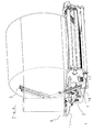
- the clamping device 1 has in the illustrated embodiment a movable actuating means 2 in the form of a lifting cylinder.
- she comprises a clamping element 3, which at its rear end 4 a Bolzenschraubtagen 5, which is guided in a slot-like longitudinal guide 6 in a housing is, on which also designed as a hydraulic cylinder actuating means 2 is supported.
- the clamping device 1 has next to the clamping element 3 nor a clamping bar 7, on which via a driver 8 acts as the lifting cylinder designed actuating means 2, wherein the clamping element 3 and the clamping bar 7 form a clamping pliers.
- the Clamping element 3 is in turn fork-shaped and acts with the clamping bar 7 together, which in turn has a clamping rail 12, the interposition supported by spring elements 13 and 14 on the clamping bar interchangeable is.
- the fork-shaped clamping element 3 can therefore the clamping rail 12 and partially overlap the clamping bar 7 and in between a piece of track Wrap wrapping or packaging material on the clamping rail 12, when the trained as a lifting cylinder actuating means 2 brought into its extended position is, as shown in FIG. 1. In this position, the rear end 4 and the bolt is the fifth of the clamping element within the longitudinal guide 6 completely moved backwards, so that the clamping element together with the clamping bar 7 is an approximately horizontal position occupies.
- an energy storage 15 in the form of a Compression spring provided on the clamping bar 7 .
- the clamping element 3 After the transfer of the clamping element 3 in the in Fig.1 shown clamping position presses the clamping element 3 on the energy storage 15 us spurs this forward. If the actuating means 2 is depressurized, can under the action of the energy accumulator 15, the clamping element 3 in such an operating position raise or slightly swivel that the clamping of the wrapping or packaging material no longer persists. However, the clamping element will also be only to raise such an area as the deflection of the energy storage 15th allows. Thereafter, the wrapping or packaging material is still running, however not clamped by the clamping element 3.
- Fig. 2 designed as a hydraulic cylinder actuating means 2 is shown retracted and has thus moved the driver 8 in the direction of the actuating means 2, so that due the pivotal support by the bolt 19 within the housing 11th the clamping bar 7 together with the clamping rail 12, the spring elements 13 and 14th and the energy storage 15 in the swung up, illustrated open position is pivoted. Due to its articulated connection at 16, the clamping element 3 pivoted in the pivoted-open position, and under appeal of the end 4 and the pin 5 in the slot guide 6.
Landscapes
- Life Sciences & Earth Sciences (AREA)
- Environmental Sciences (AREA)
- Basic Packing Technique (AREA)
- Storage Of Harvested Produce (AREA)
- Packaging Of Special Articles (AREA)
Abstract
Description
- Fig. 1
- ein Ausführungsbeispiel eines Klemmelementes mit zugehörigem Kraftspeicher in der Klemmstellung in einer perspektivischen Darstellung,
- Fig. 2
- eine zu Fig. 1 analoge Darstellung in geöffnetem hochverschwenktem Zustand des Klemmelementes, und
- Fig. 3
- eine Einzelteildarstellung der in den Fig. 1 und 2 veranschaulichten Teile der Vorrichtung in einer auseinander gezogenen Darstellung,
- Fig.4
- eine perspektivische Ansicht einer Vorrichtung zum Umhüllen und Verpacken in eine Phase vor dem Zusammenfalten und Abtrennen einer Verpackungsmaterialbahn.
Claims (12)
- Vorrichtung zum Umhüllen oder Verpacken von insbesondere landwirtschaftlichen Erntegutballen, vorzugsweise eine, eine Presskammer umfassende landwirtschaftliche Aufsammelpresse für zu umhüllendes Erntegut, mit einer ein Umhüllungs- bzw. Verpackungsmaterial aufnehmenden Wickeleinheit, der eine ein bewegliches Stellmittel (2) aufweisende Klemmeinrichtung zur Festlegung einer Verpackungs- bzw. Umhüllungsmaterialbahn zugeordnet ist, wobei die Klemmeinrichtung ein von dem beweglichen Stellmittel (2) in eine Klemmstellung überführbares Klemmelement (3) aufweist, dadurch gekennzeichnet, dass das Klemmelement (3) von dem Stellmittel (2) gegen die Kraft eines Kraftspeichers (15) in seine Klemmstellung überführbar und von dem Kraftspeicher (15) in eine außerhalb der Klemmstellung gelegene sowie von dem Kraftspeicher (15) vorgebbare Betriebsstellung bewegbar ist.
- Vorrichtung nach Anspruch 1, dadurch gekennzeichnet, dass das Klemmelement (3) von dem Kraftspeicher (15) in einer Drucklosstellung des Stellmittels (2) in seine von dem Kraftspeicher (15) vorgebbare Betriebsstellung bewegbar ist.
- Vorrichtung nach Anspruch 1 oder 2, dadurch gekennzeichnet, dass der Kraftspeicher (15) als Druckfeder ausgebildet ist.
- Vorrichtung nach einem der Ansprüche 1 bis 3, dadurch gekennzeichnet, dass das Klemmelement (3) relativ zu einem den Kraftspeicher (15) tragenden Klemmbalken (7) bewegbar ist und eine Klemmzange ausgebildet.
- Vorrichtung nach einem der Ansprüche 1 bis 4, dadurch gekennzeichnet, dass das Klemmelement (3) einenends in einer Führung (6) geführt und in dieser translatorisch bewegbar ist.
- Vorrichtung nach einem der Ansprüche 1 bis 5, dadurch gekennzeichnet, dass das Klemmelement (3) von dem Stellmittel (2) in eine hochverschwenkte Öffnungsstellung und aus dieser von dem Stellmittel (2) in seine Klemmstellung überführbar ist.
- Vorrichtung nach einem der Ansprüche 4 bis 6, dadurch gekennzeichnet, dass das Klemmelement (3) über den Klemmbalken (7) in die hochverschwenkte Öffnungsstellung verschwenkbar ist.
- Vorrichtung nach einem der Ansprüche 4 bis 7, dadurch gekennzeichnet, dass der Klemmbalken (7) und das Klemmelement (3) schnabelförmig auf und zu bewegbar sind und dass der Klemmbalken (7) eine elastisch abgestützte Klemmschiene (12) trägt.
- Vorrichtung nach einem der Ansprüche 4 bis 8, dadurch gekennzeichnet, dass das Klemmelement (3) gabelförmig ausgebildet ist und den Klemmbalken (7) bereichsweise übergreift.
- Vorrichtung nach einem der Ansprüche 1 bis 9, dadurch gekennzeichnet, dass mittels des Klemmelementes (3) und des Klemmbalkens (7) bei ihrer Überführung aus der Öffnungsstellung in die Klemmstellung eine Faltung des Umhüllungs- oder Verpackungsmaterials erreichbar ist.
- Vorrichtung nach einem der Ansprüche 1 bis 10, dadurch gekennzeichnet, dass an der Vorrichtung (1) ein Schneid- oder Trennelement (17) zum Abtrennen einer Umhüllungs- oder Verpackungsmaterialbahn abstützbar ist.
- Vorrichtung nach Anspruch 11, dadurch gekennzeichnet, dass das Schneidoder Trennelement (17) aus einer im wesentlichen parallel zu dem Klemmelement (3) gelegenen Ausgangsstellung in eine Schneidstellung hochschwenkbar ist.
Applications Claiming Priority (2)
| Application Number | Priority Date | Filing Date | Title |
|---|---|---|---|
| DE10334679 | 2003-07-30 | ||
| DE10334679A DE10334679B4 (de) | 2003-07-30 | 2003-07-30 | Vorrichtung zum Umhüllen oder Verpacken von insbesondere landwirtschaftlichen Erntegutballen |
Publications (2)
| Publication Number | Publication Date |
|---|---|
| EP1502494A1 true EP1502494A1 (de) | 2005-02-02 |
| EP1502494B1 EP1502494B1 (de) | 2007-09-26 |
Family
ID=33521472
Family Applications (1)
| Application Number | Title | Priority Date | Filing Date |
|---|---|---|---|
| EP04017615A Expired - Lifetime EP1502494B1 (de) | 2003-07-30 | 2004-07-26 | Vorrichtung zum Umhüllen oder Verpacken von insbesondere landwirtschaftlichen Erntegutballen |
Country Status (3)
| Country | Link |
|---|---|
| EP (1) | EP1502494B1 (de) |
| AT (1) | ATE373949T1 (de) |
| DE (2) | DE10334679B4 (de) |
Cited By (1)
| Publication number | Priority date | Publication date | Assignee | Title |
|---|---|---|---|---|
| EP3138384A1 (de) * | 2015-09-07 | 2017-03-08 | Usines Claas France S.A.S | Wickelvorrichtung für eine ballenpresse und betriebsverfahren dafür |
Families Citing this family (2)
| Publication number | Priority date | Publication date | Assignee | Title |
|---|---|---|---|---|
| DE102009010547B3 (de) * | 2009-02-25 | 2010-06-24 | Siegfried Unseld | Schneideinrichtung für Wickelmaterialbahnen |
| DE202016004710U1 (de) | 2016-08-01 | 2017-11-03 | Pöttinger Landtechnik Gmbh | Ballenwickler |
Citations (3)
| Publication number | Priority date | Publication date | Assignee | Title |
|---|---|---|---|---|
| EP0367529A1 (de) * | 1988-10-31 | 1990-05-09 | Kverneland Underhaug A/S | Automatische Umhüllvorrichtung für Rundballen |
| GB2249077A (en) * | 1990-09-19 | 1992-04-29 | Wellmount Ltd | Bale wrapping apparatus |
| FR2679105A1 (fr) * | 1991-07-17 | 1993-01-22 | Doucet Freres | Machine a emballer des balles rondes de fourrage. |
Family Cites Families (2)
| Publication number | Priority date | Publication date | Assignee | Title |
|---|---|---|---|---|
| GB2242667B (en) * | 1990-04-03 | 1994-02-16 | Lawrence Edwards & Co | Improvements in or relating to wrapping apparatus |
| DE9414220U1 (de) * | 1994-09-02 | 1994-11-24 | Bräutigam, Klaus, Dipl.-Ing., 34281 Gudensberg | Vorrichtung zum Einwickeln von Siloballen |
-
2003
- 2003-07-30 DE DE10334679A patent/DE10334679B4/de not_active Expired - Fee Related
-
2004
- 2004-07-26 EP EP04017615A patent/EP1502494B1/de not_active Expired - Lifetime
- 2004-07-26 AT AT04017615T patent/ATE373949T1/de active
- 2004-07-26 DE DE502004005065T patent/DE502004005065D1/de not_active Expired - Lifetime
Patent Citations (3)
| Publication number | Priority date | Publication date | Assignee | Title |
|---|---|---|---|---|
| EP0367529A1 (de) * | 1988-10-31 | 1990-05-09 | Kverneland Underhaug A/S | Automatische Umhüllvorrichtung für Rundballen |
| GB2249077A (en) * | 1990-09-19 | 1992-04-29 | Wellmount Ltd | Bale wrapping apparatus |
| FR2679105A1 (fr) * | 1991-07-17 | 1993-01-22 | Doucet Freres | Machine a emballer des balles rondes de fourrage. |
Cited By (1)
| Publication number | Priority date | Publication date | Assignee | Title |
|---|---|---|---|---|
| EP3138384A1 (de) * | 2015-09-07 | 2017-03-08 | Usines Claas France S.A.S | Wickelvorrichtung für eine ballenpresse und betriebsverfahren dafür |
Also Published As
| Publication number | Publication date |
|---|---|
| DE502004005065D1 (de) | 2007-11-08 |
| DE10334679B4 (de) | 2005-10-20 |
| ATE373949T1 (de) | 2007-10-15 |
| EP1502494B1 (de) | 2007-09-26 |
| DE10334679A1 (de) | 2005-03-03 |
Similar Documents
| Publication | Publication Date | Title |
|---|---|---|
| DE69709981T2 (de) | Rundballenpresse | |
| DE1782382C3 (de) | Ladewagen mit einer ballenbildenden Ladeeinrichtung | |
| EP0157898B1 (de) | Vorrichtung zum Binden von Rollballen aus landwirtschaftlichem Erntegut | |
| EP0075252B1 (de) | Automatische Bindeeinrichtung für Maschinen zum Herstellen von zylindrischen Ballen aus Erntegut in einer Wickelkammer | |
| EP4108069B1 (de) | Rundballenpresse | |
| DE3418681A1 (de) | Rollballenpresse fuer landwirtschaftliche halmgueter mit einer huellvorrichtung | |
| DE202018101650U1 (de) | Garnknoteranordnung zum Knoten von Garn und Ballenpressvorrichtung | |
| EP3391728B1 (de) | Ballenpresse | |
| DE3436883A1 (de) | Verfahren zum herstellen von rechteckigen grossballen aus geschnittenem halmgut und grossballenpresse | |
| DE3445060C2 (de) | ||
| DE68911838T2 (de) | Riemenspannungsvorrichtung für eine Rundballenpresse. | |
| DE102005055375B4 (de) | Rundballenpresse | |
| EP1401710B1 (de) | Knoterhaken und damit ausgerüsteter garnknoter | |
| DE10153517B4 (de) | Bindevorrichtung für eine Rundballenpresse | |
| EP1502494A1 (de) | Vorrichtung zum Unhüllen oder Verpacken von insbesondere landwirtschaflichen Erntegutballen | |
| EP4261028B1 (de) | Kanalballenpresse mit kreuzabbindung | |
| EP1502495B1 (de) | Vorrichtung zum Umhüllen oder Verpacken von insbesondere landwirtschaftlichen Erntegutballen | |
| EP1982576B1 (de) | Ballenpresse mit Knotereinrichtung | |
| DE102017003884B4 (de) | Ballenpresse | |
| DE2457087A1 (de) | Vorrichtung und verfahren zum pressen und einbinden von ballen | |
| DE10139450A1 (de) | Ballenpresse | |
| DE4031695C2 (de) | Vorrichtung zur Erhöhung der Bindesicherheit und -qualität an Großballenpressen | |
| DE102021106209A1 (de) | Ballenpresse | |
| DE20211580U1 (de) | Maschine zum Aufnehmen und Pressen von landwirtschaftlichem Erntegut | |
| DD150833A1 (de) | Presse zur herstellung von grossballen aus kleinballen |
Legal Events
| Date | Code | Title | Description |
|---|---|---|---|
| PUAI | Public reference made under article 153(3) epc to a published international application that has entered the european phase |
Free format text: ORIGINAL CODE: 0009012 |
|
| AK | Designated contracting states |
Kind code of ref document: A1 Designated state(s): AT BE BG CH CY CZ DE DK EE ES FI FR GB GR HU IE IT LI LU MC NL PL PT RO SE SI SK TR |
|
| AX | Request for extension of the european patent |
Extension state: AL HR LT LV MK |
|
| 17P | Request for examination filed |
Effective date: 20050718 |
|
| AKX | Designation fees paid |
Designated state(s): AT BE BG CH CY CZ DE DK EE ES FI FR GB GR HU IE IT LI LU MC NL PL PT RO SE SI SK TR |
|
| GRAP | Despatch of communication of intention to grant a patent |
Free format text: ORIGINAL CODE: EPIDOSNIGR1 |
|
| GRAS | Grant fee paid |
Free format text: ORIGINAL CODE: EPIDOSNIGR3 |
|
| RIN1 | Information on inventor provided before grant (corrected) |
Inventor name: MARTENSEN, KLAUS, DR.-ING. Inventor name: KRONE, BERNARD, DR.-ING. E.H. |
|
| GRAA | (expected) grant |
Free format text: ORIGINAL CODE: 0009210 |
|
| AK | Designated contracting states |
Kind code of ref document: B1 Designated state(s): AT BE BG CH CY CZ DE DK EE ES FI FR GB GR HU IE IT LI LU MC NL PL PT RO SE SI SK TR |
|
| REG | Reference to a national code |
Ref country code: GB Ref legal event code: FG4D Free format text: NOT ENGLISH |
|
| REG | Reference to a national code |
Ref country code: CH Ref legal event code: EP |
|
| REF | Corresponds to: |
Ref document number: 502004005065 Country of ref document: DE Date of ref document: 20071108 Kind code of ref document: P |
|
| REG | Reference to a national code |
Ref country code: DE Ref legal event code: R096 Ref document number: 502004005065 Country of ref document: DE Effective date: 20071108 |
|
| REG | Reference to a national code |
Ref country code: IE Ref legal event code: FG4D Free format text: LANGUAGE OF EP DOCUMENT: GERMAN |
|
| PG25 | Lapsed in a contracting state [announced via postgrant information from national office to epo] |
Ref country code: PL Free format text: LAPSE BECAUSE OF FAILURE TO SUBMIT A TRANSLATION OF THE DESCRIPTION OR TO PAY THE FEE WITHIN THE PRESCRIBED TIME-LIMIT Effective date: 20070926 |
|
| GBV | Gb: ep patent (uk) treated as always having been void in accordance with gb section 77(7)/1977 [no translation filed] | ||
| PG25 | Lapsed in a contracting state [announced via postgrant information from national office to epo] |
Ref country code: GR Free format text: LAPSE BECAUSE OF FAILURE TO SUBMIT A TRANSLATION OF THE DESCRIPTION OR TO PAY THE FEE WITHIN THE PRESCRIBED TIME-LIMIT Effective date: 20071227 Ref country code: ES Free format text: LAPSE BECAUSE OF FAILURE TO SUBMIT A TRANSLATION OF THE DESCRIPTION OR TO PAY THE FEE WITHIN THE PRESCRIBED TIME-LIMIT Effective date: 20080106 |
|
| PG25 | Lapsed in a contracting state [announced via postgrant information from national office to epo] |
Ref country code: SK Free format text: LAPSE BECAUSE OF FAILURE TO SUBMIT A TRANSLATION OF THE DESCRIPTION OR TO PAY THE FEE WITHIN THE PRESCRIBED TIME-LIMIT Effective date: 20070926 Ref country code: PT Free format text: LAPSE BECAUSE OF FAILURE TO SUBMIT A TRANSLATION OF THE DESCRIPTION OR TO PAY THE FEE WITHIN THE PRESCRIBED TIME-LIMIT Effective date: 20080226 Ref country code: CZ Free format text: LAPSE BECAUSE OF FAILURE TO SUBMIT A TRANSLATION OF THE DESCRIPTION OR TO PAY THE FEE WITHIN THE PRESCRIBED TIME-LIMIT Effective date: 20070926 |
|
| ET | Fr: translation filed | ||
| PG25 | Lapsed in a contracting state [announced via postgrant information from national office to epo] |
Ref country code: RO Free format text: LAPSE BECAUSE OF FAILURE TO SUBMIT A TRANSLATION OF THE DESCRIPTION OR TO PAY THE FEE WITHIN THE PRESCRIBED TIME-LIMIT Effective date: 20070926 Ref country code: SE Free format text: LAPSE BECAUSE OF FAILURE TO SUBMIT A TRANSLATION OF THE DESCRIPTION OR TO PAY THE FEE WITHIN THE PRESCRIBED TIME-LIMIT Effective date: 20071226 |
|
| PG25 | Lapsed in a contracting state [announced via postgrant information from national office to epo] |
Ref country code: DK Free format text: LAPSE BECAUSE OF FAILURE TO SUBMIT A TRANSLATION OF THE DESCRIPTION OR TO PAY THE FEE WITHIN THE PRESCRIBED TIME-LIMIT Effective date: 20070926 |
|
| PLBE | No opposition filed within time limit |
Free format text: ORIGINAL CODE: 0009261 |
|
| STAA | Information on the status of an ep patent application or granted ep patent |
Free format text: STATUS: NO OPPOSITION FILED WITHIN TIME LIMIT |
|
| 26N | No opposition filed |
Effective date: 20080627 |
|
| REG | Reference to a national code |
Ref country code: DE Ref legal event code: R097 Ref document number: 502004005065 Country of ref document: DE Effective date: 20080627 |
|
| PG25 | Lapsed in a contracting state [announced via postgrant information from national office to epo] |
Ref country code: GB Free format text: LAPSE BECAUSE OF FAILURE TO SUBMIT A TRANSLATION OF THE DESCRIPTION OR TO PAY THE FEE WITHIN THE PRESCRIBED TIME-LIMIT Effective date: 20070926 |
|
| REG | Reference to a national code |
Ref country code: CH Ref legal event code: PL |
|
| PG25 | Lapsed in a contracting state [announced via postgrant information from national office to epo] |
Ref country code: MC Free format text: LAPSE BECAUSE OF NON-PAYMENT OF DUE FEES Effective date: 20080731 |
|
| PG25 | Lapsed in a contracting state [announced via postgrant information from national office to epo] |
Ref country code: EE Free format text: LAPSE BECAUSE OF FAILURE TO SUBMIT A TRANSLATION OF THE DESCRIPTION OR TO PAY THE FEE WITHIN THE PRESCRIBED TIME-LIMIT Effective date: 20070926 |
|
| PG25 | Lapsed in a contracting state [announced via postgrant information from national office to epo] |
Ref country code: SI Free format text: LAPSE BECAUSE OF FAILURE TO SUBMIT A TRANSLATION OF THE DESCRIPTION OR TO PAY THE FEE WITHIN THE PRESCRIBED TIME-LIMIT Effective date: 20070926 Ref country code: LI Free format text: LAPSE BECAUSE OF NON-PAYMENT OF DUE FEES Effective date: 20080731 Ref country code: CH Free format text: LAPSE BECAUSE OF NON-PAYMENT OF DUE FEES Effective date: 20080731 |
|
| PG25 | Lapsed in a contracting state [announced via postgrant information from national office to epo] |
Ref country code: CY Free format text: LAPSE BECAUSE OF FAILURE TO SUBMIT A TRANSLATION OF THE DESCRIPTION OR TO PAY THE FEE WITHIN THE PRESCRIBED TIME-LIMIT Effective date: 20070926 |
|
| PG25 | Lapsed in a contracting state [announced via postgrant information from national office to epo] |
Ref country code: BG Free format text: LAPSE BECAUSE OF FAILURE TO SUBMIT A TRANSLATION OF THE DESCRIPTION OR TO PAY THE FEE WITHIN THE PRESCRIBED TIME-LIMIT Effective date: 20071226 |
|
| PG25 | Lapsed in a contracting state [announced via postgrant information from national office to epo] |
Ref country code: LU Free format text: LAPSE BECAUSE OF NON-PAYMENT OF DUE FEES Effective date: 20080726 Ref country code: HU Free format text: LAPSE BECAUSE OF FAILURE TO SUBMIT A TRANSLATION OF THE DESCRIPTION OR TO PAY THE FEE WITHIN THE PRESCRIBED TIME-LIMIT Effective date: 20080327 |
|
| PG25 | Lapsed in a contracting state [announced via postgrant information from national office to epo] |
Ref country code: TR Free format text: LAPSE BECAUSE OF FAILURE TO SUBMIT A TRANSLATION OF THE DESCRIPTION OR TO PAY THE FEE WITHIN THE PRESCRIBED TIME-LIMIT Effective date: 20070926 |
|
| REG | Reference to a national code |
Ref country code: FR Ref legal event code: PLFP Year of fee payment: 13 |
|
| REG | Reference to a national code |
Ref country code: FR Ref legal event code: PLFP Year of fee payment: 14 |
|
| REG | Reference to a national code |
Ref country code: FR Ref legal event code: PLFP Year of fee payment: 15 |
|
| REG | Reference to a national code |
Ref country code: BE Ref legal event code: HC Owner name: MASCHINENFABRIK BERNARD KRONE GMBH & CO. KG; DE Free format text: DETAILS ASSIGNMENT: CHANGE OF OWNER(S), CHANGE OF OWNER(S) NAME Effective date: 20210209 |
|
| REG | Reference to a national code |
Ref country code: DE Ref legal event code: R081 Ref document number: 502004005065 Country of ref document: DE Owner name: KRONE AGRICULTURE SE, DE Free format text: FORMER OWNER: MASCHINENFABRIK BERNARD KRONE GMBH, 48480 SPELLE, DE |
|
| REG | Reference to a national code |
Ref country code: FI Ref legal event code: PCE Owner name: KRONE AGRICULTURE SE |
|
| REG | Reference to a national code |
Ref country code: DE Ref legal event code: R084 Ref document number: 502004005065 Country of ref document: DE |
|
| REG | Reference to a national code |
Ref country code: AT Ref legal event code: PC Ref document number: 373949 Country of ref document: AT Kind code of ref document: T Owner name: KRONE AGRICULTURE SE, DE Effective date: 20211022 |
|
| REG | Reference to a national code |
Ref country code: NL Ref legal event code: PD Owner name: KRONE AGRICULTURE SE; DE Free format text: DETAILS ASSIGNMENT: CHANGE OF OWNER(S), MERGE; FORMER OWNER NAME: MASCHINENFABRIK KRONE BETEILIGUNGS-GMBH Effective date: 20211126 Ref country code: NL Ref legal event code: HC Owner name: MASCHINENFABRIK KRONE BETEILIGUNGS-GMBH; DE Free format text: DETAILS ASSIGNMENT: CHANGE OF OWNER(S), CHANGE OF OWNER(S) NAME; FORMER OWNER NAME: MASCHINENFABRIK BERNARD KRONE GMBH Effective date: 20211126 |
|
| PGFP | Annual fee paid to national office [announced via postgrant information from national office to epo] |
Ref country code: NL Payment date: 20220720 Year of fee payment: 19 |
|
| PGFP | Annual fee paid to national office [announced via postgrant information from national office to epo] |
Ref country code: IT Payment date: 20220729 Year of fee payment: 19 Ref country code: IE Payment date: 20220720 Year of fee payment: 19 Ref country code: FI Payment date: 20220719 Year of fee payment: 19 Ref country code: DE Payment date: 20220621 Year of fee payment: 19 Ref country code: AT Payment date: 20220718 Year of fee payment: 19 |
|
| PGFP | Annual fee paid to national office [announced via postgrant information from national office to epo] |
Ref country code: FR Payment date: 20220727 Year of fee payment: 19 Ref country code: BE Payment date: 20220720 Year of fee payment: 19 |
|
| P01 | Opt-out of the competence of the unified patent court (upc) registered |
Effective date: 20230517 |
|
| REG | Reference to a national code |
Ref country code: DE Ref legal event code: R119 Ref document number: 502004005065 Country of ref document: DE |
|
| REG | Reference to a national code |
Ref country code: NL Ref legal event code: MM Effective date: 20230801 |
|
| REG | Reference to a national code |
Ref country code: AT Ref legal event code: MM01 Ref document number: 373949 Country of ref document: AT Kind code of ref document: T Effective date: 20230726 |
|
| REG | Reference to a national code |
Ref country code: BE Ref legal event code: MM Effective date: 20230731 |
|
| PG25 | Lapsed in a contracting state [announced via postgrant information from national office to epo] |
Ref country code: NL Free format text: LAPSE BECAUSE OF NON-PAYMENT OF DUE FEES Effective date: 20230801 |
|
| PG25 | Lapsed in a contracting state [announced via postgrant information from national office to epo] |
Ref country code: AT Free format text: LAPSE BECAUSE OF NON-PAYMENT OF DUE FEES Effective date: 20230726 |
|
| REG | Reference to a national code |
Ref country code: IE Ref legal event code: MM4A |
|
| PG25 | Lapsed in a contracting state [announced via postgrant information from national office to epo] |
Ref country code: NL Free format text: LAPSE BECAUSE OF NON-PAYMENT OF DUE FEES Effective date: 20230801 Ref country code: FI Free format text: LAPSE BECAUSE OF NON-PAYMENT OF DUE FEES Effective date: 20230726 Ref country code: DE Free format text: LAPSE BECAUSE OF NON-PAYMENT OF DUE FEES Effective date: 20240201 Ref country code: AT Free format text: LAPSE BECAUSE OF NON-PAYMENT OF DUE FEES Effective date: 20230726 |
|
| PG25 | Lapsed in a contracting state [announced via postgrant information from national office to epo] |
Ref country code: FR Free format text: LAPSE BECAUSE OF NON-PAYMENT OF DUE FEES Effective date: 20230731 Ref country code: BE Free format text: LAPSE BECAUSE OF NON-PAYMENT OF DUE FEES Effective date: 20230731 |
|
| PG25 | Lapsed in a contracting state [announced via postgrant information from national office to epo] |
Ref country code: IE Free format text: LAPSE BECAUSE OF NON-PAYMENT OF DUE FEES Effective date: 20230726 |
|
| PG25 | Lapsed in a contracting state [announced via postgrant information from national office to epo] |
Ref country code: IT Free format text: LAPSE BECAUSE OF NON-PAYMENT OF DUE FEES Effective date: 20230726 Ref country code: IE Free format text: LAPSE BECAUSE OF NON-PAYMENT OF DUE FEES Effective date: 20230726 |