EP1502794A2 - Vorrichtung zum Vermeiden einer Fehlbetankung bei Kraftfahrzeugen - Google Patents
Vorrichtung zum Vermeiden einer Fehlbetankung bei Kraftfahrzeugen Download PDFInfo
- Publication number
- EP1502794A2 EP1502794A2 EP04017171A EP04017171A EP1502794A2 EP 1502794 A2 EP1502794 A2 EP 1502794A2 EP 04017171 A EP04017171 A EP 04017171A EP 04017171 A EP04017171 A EP 04017171A EP 1502794 A2 EP1502794 A2 EP 1502794A2
- Authority
- EP
- European Patent Office
- Prior art keywords
- neck
- filler neck
- insert
- flange
- tank
- Prior art date
- Legal status (The legal status is an assumption and is not a legal conclusion. Google has not performed a legal analysis and makes no representation as to the accuracy of the status listed.)
- Granted
Links
Images


Classifications
-
- B—PERFORMING OPERATIONS; TRANSPORTING
- B60—VEHICLES IN GENERAL
- B60K—ARRANGEMENT OR MOUNTING OF PROPULSION UNITS OR OF TRANSMISSIONS IN VEHICLES; ARRANGEMENT OR MOUNTING OF PLURAL DIVERSE PRIME-MOVERS IN VEHICLES; AUXILIARY DRIVES FOR VEHICLES; INSTRUMENTATION OR DASHBOARDS FOR VEHICLES; ARRANGEMENTS IN CONNECTION WITH COOLING, AIR INTAKE, GAS EXHAUST OR FUEL SUPPLY OF PROPULSION UNITS IN VEHICLES
- B60K15/00—Arrangement in connection with fuel supply of combustion engines or other fuel consuming energy converters, e.g. fuel cells; Mounting or construction of fuel tanks
- B60K15/03—Fuel tanks
- B60K15/04—Tank inlets
-
- B—PERFORMING OPERATIONS; TRANSPORTING
- B60—VEHICLES IN GENERAL
- B60K—ARRANGEMENT OR MOUNTING OF PROPULSION UNITS OR OF TRANSMISSIONS IN VEHICLES; ARRANGEMENT OR MOUNTING OF PLURAL DIVERSE PRIME-MOVERS IN VEHICLES; AUXILIARY DRIVES FOR VEHICLES; INSTRUMENTATION OR DASHBOARDS FOR VEHICLES; ARRANGEMENTS IN CONNECTION WITH COOLING, AIR INTAKE, GAS EXHAUST OR FUEL SUPPLY OF PROPULSION UNITS IN VEHICLES
- B60K15/00—Arrangement in connection with fuel supply of combustion engines or other fuel consuming energy converters, e.g. fuel cells; Mounting or construction of fuel tanks
- B60K15/03—Fuel tanks
- B60K2015/03328—Arrangements or special measures related to fuel tanks or fuel handling
- B60K2015/03348—Arrangements or special measures related to fuel tanks or fuel handling for supplying additives to fuel
-
- B—PERFORMING OPERATIONS; TRANSPORTING
- B60—VEHICLES IN GENERAL
- B60K—ARRANGEMENT OR MOUNTING OF PROPULSION UNITS OR OF TRANSMISSIONS IN VEHICLES; ARRANGEMENT OR MOUNTING OF PLURAL DIVERSE PRIME-MOVERS IN VEHICLES; AUXILIARY DRIVES FOR VEHICLES; INSTRUMENTATION OR DASHBOARDS FOR VEHICLES; ARRANGEMENTS IN CONNECTION WITH COOLING, AIR INTAKE, GAS EXHAUST OR FUEL SUPPLY OF PROPULSION UNITS IN VEHICLES
- B60K15/00—Arrangement in connection with fuel supply of combustion engines or other fuel consuming energy converters, e.g. fuel cells; Mounting or construction of fuel tanks
- B60K15/03—Fuel tanks
- B60K2015/03328—Arrangements or special measures related to fuel tanks or fuel handling
- B60K2015/03361—Arrangements or special measures related to fuel tanks or fuel handling for checking the quality or quantity of fuel during filling of fuel tank
-
- B—PERFORMING OPERATIONS; TRANSPORTING
- B60—VEHICLES IN GENERAL
- B60K—ARRANGEMENT OR MOUNTING OF PROPULSION UNITS OR OF TRANSMISSIONS IN VEHICLES; ARRANGEMENT OR MOUNTING OF PLURAL DIVERSE PRIME-MOVERS IN VEHICLES; AUXILIARY DRIVES FOR VEHICLES; INSTRUMENTATION OR DASHBOARDS FOR VEHICLES; ARRANGEMENTS IN CONNECTION WITH COOLING, AIR INTAKE, GAS EXHAUST OR FUEL SUPPLY OF PROPULSION UNITS IN VEHICLES
- B60K15/00—Arrangement in connection with fuel supply of combustion engines or other fuel consuming energy converters, e.g. fuel cells; Mounting or construction of fuel tanks
- B60K15/03—Fuel tanks
- B60K15/04—Tank inlets
- B60K2015/0458—Details of the tank inlet
- B60K2015/0483—Means to inhibit the introduction of too small or too big filler nozzles
-
- F—MECHANICAL ENGINEERING; LIGHTING; HEATING; WEAPONS; BLASTING
- F01—MACHINES OR ENGINES IN GENERAL; ENGINE PLANTS IN GENERAL; STEAM ENGINES
- F01N—GAS-FLOW SILENCERS OR EXHAUST APPARATUS FOR MACHINES OR ENGINES IN GENERAL; GAS-FLOW SILENCERS OR EXHAUST APPARATUS FOR INTERNAL-COMBUSTION ENGINES
- F01N2610/00—Adding substances to exhaust gases
- F01N2610/14—Arrangements for the supply of substances, e.g. conduits
- F01N2610/1406—Storage means for substances, e.g. tanks or reservoirs
- F01N2610/1413—Inlet and filling arrangements therefore
Definitions
- the invention relates to a device for avoiding a Misfuelling in motor vehicles with one on the one component the tank body in a fluid tank in motor vehicles forming Tankstutzen to be attached insert for receiving a to the Forming the insert adapted dispensing gun, wherein the annular Insert in its wall a nozzle enclosing and with a arranged in the fuel nozzle locking mechanism cooperating magnet absorbs.
- the invention is therefore based on the object to a possibility create a misfueling insert in the filler neck, without making any changes to the design of conventional fluid tanks , including a retrofitting or conversion existing, already in Trucks built-in tanks for the absorption of urea possible should be.
- the invention provides in its basic idea that in the Tankstutzen to be used on one of the tank neck of the Tank body attached filler neck is replaceable held.
- the invention thus has a separate, in the filler neck of a for example, the storage of urea serving tanks insertable and to be determined on the filler neck insert for Subject arranged to be related to the Insertion length of the fuel nozzle correct position with respect to the assignment of Ring magnet to the fuel nozzle adopts.
- the Expand use for example, to replace the ring magnet, the holder of the insert is designed to be detachable on the filler neck.
- the invention is in each case to all fluid tanks, also in the form of Liquid and in particular fuel tanks applicable.
- a first embodiment of the invention is to determine the in the filler neck reaching insert at the filler neck one provided separate bracket, which consists of a with a wall in the Tank neck to be used and with one at its upper end trained circumferential flange on the tank neck supporting neck piece consists, wherein in an area of the neck opening for receiving of fasteners for the interchangeable mounting of the insert the neck piece are formed, and wherein the openings receiving Area of the neck piece of the tank neck is solvable.
- the Attachment of the assembly formed from throat and filler neck proposed on a metal tank that the Attachment of the assembly formed from throat and filler neck On a metal tank, the filler neck on the outside with the tank body is welded and the flange of the neck piece in two parts with two themselves is formed in a partial region overlapping partial flanges, wherein a partial flange over the edge fixed to the filler neck is connected and the other partial flange firmly with the use enclosing wall, and being the use of the supporting partial flange on the partial flange and in the Overlap area releasably connected and out of the filler neck is removable.
- the Neckpiece a cylindrical shape with one insert at least Partially enclosing wall and the Fasteners pierce the wall of the neck piece and into the Extend the wall of the insert.
- the neck piece a stepped shape with an outer diameter of the inner diameter of the Tank neck adapted upper cylinder section and with a with the formation of an internally receding circumferential step subsequent lower cylinder section with a for recording the nozzle set inside diameter of the insert matched outer diameter has such that the insert with its inner diameter on the lower cylinder section of the Neckpiece is slidable and the fasteners through in the area the stage arranged openings frontally into the wall of the Insert are insertable.
- This has the advantage that the upper edge of possibly existing plastic insert lies outside the lead-in area of the fuel nozzle and through is protected inside reentrant step of the neck piece, the Fuel nozzle only when inserted in the filler neck or the neck piece can strike the level.
- the neckpiece with an upper and a lower cylinder portion can after a Embodiment of the invention be provided that the Internal thread in the upper cylinder portion of the filler neck trained neckpiece is arranged.
- the upper flange of the Filler neck formed the upper edge of the neck Envelope bent bent around and attached to it.
- one of the embodiment of the invention provides that in the Production of the plastic tank on the filler neck a reinforcing ring with a circumferential the upper edge of the filler neck forming Flange and a reaching into the filler neck wall section is enclosed in the plastic, the attachment of the later in the filler neck to be used bracket to the flange of Reinforcement ring is executable.
- the Reinforcing ring with the plastic tank can continue to be provided be that the reinforcing ring on the outside of his Wall section with protruding and in the plastic material protruding tabs is provided.
- a compact insert for holding the Magnet forming embodiment that the use consists of two telescoping parts, with outer part and Inner part each of a cylindrical section with a larger one Diameter and an adjoining cylindrical section exist with a smaller diameter and outer part and inner part fit into each other can be inserted, and wherein the longitudinal extent of the larger diameter cylindrical portion of the Inside to form a free space in the area between the Sections of different diameters existing stages shorter is dimensioned as the longitudinal extent of the associated portion of the Outer part, wherein it can be further provided that the magnet in between the inner part and the outer part in the area of their steps formed free space is arranged.
- an attachment of the Use of a metal tank body is in question, is provided according to an embodiment that the use retaining filler neck overlaps the filler neck and the outside with welded to the tank body.
- a reinforcing ring already in the manufacture of the Plastic tank body in the upper edge of the filler neck is enclosed, with the patch on the filler neck Filler neck with the reinforcing ring by means of screw connections is connectable.
- the filler supports with the inner flange formed on it on the reinforcing ring of the Tankstutzens auflagert and the fittings, including the Use of attachment of the filler neck on the filler neck serve.
- an additional Seal is arranged between the filler neck and the filler neck.
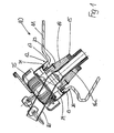
- a liquid tank 10 made of plastic, suitable for the Urea intake is provided, the tank body 11 a Tank neck 12 has, which is arranged in a neck extension 26 and has an upper edge 13.
- a separate filler neck 24 as a carrier a closure lid 25 in a manner to be described attached is on the filler neck 12 .
- a misfueling insert 14 in held in a manner to be described, which in its wall a ring magnet 15 holds.
- One in the filler neck 12 and in the insert 14 servesstckende fuel nozzle 16 extends with the trunk 16a so deep into the insert 14, that the ring magnet 15 is not further Locking device shown in the trunk 16a can act upon.
- the insert 14 is on a serving as a support neck 17th fastened, wherein the neck piece 17 with an upper peripheral flange 18 on the upper edge 13 of the neck extension 26 of the filler neck 12th auflagert and with a wall 19 inside the tank neck 12th protrudes.
- neck 17 results in the flange 18 of the retaining piece 17 screw holes 20th formed by which screws 21 in the upper edge 13 of the Neck neck 26 of the fuel filler neck 12 are screwed, so that the Neck 17 fixed to the plastic tank body 11th is fixed. Furthermore, in the wall 19 of the neck piece 17th Screw holes 22 through which screws 23 are rotated, which extend into the insert 14 or its wall and so the Set insert 14 on the neck piece 17.
- the for the attachment of the insert provided screw holes 22 are here formed in the stage 31, so that the appropriate provided Screws 23 from above into the front side of the insert 14th can be screwed.
- the neck piece 17 has at its upper flange 18th in the manner described for Figures 2 and 3 screw holes 20 for Screw 21, by means of which the neck piece 17 on the tank body 11th is fastened.
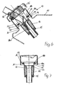
- FIG. 6 and 7 shows the Training of the neck 17 and filler neck 24 formed Assembly when mounting this assembly to a metal tank.
- the flange is 18th formed divided, wherein the one partial flange 18 a fixed over the edge 27 connected to the filler neck 24 and remains, while the inner Flange portion 18b as part of the insert 14 supporting part of the neck piece 17 is superimposed on the sub-flange 18 a from above, so that the partial flange 18b with the insert 14 hanging from the latter Partial flange 18a can be lifted and removed from the filler neck 24.
- connection of the two partial flanges 18a, 18b can, for example be made by a screw 41, either the thread in one or both partial flanges 18a, 18b cut may be, or on the underside of the partial flange 18 a a associated nut is permanently attached, in the one correspondingly guided through the sub-flange 18b screw 41st can be screwed.
- Other suitable attachment methods are alternatively conceivable.
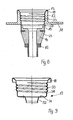
- FIGs 8 and 9 is another type of connection of a Filler neck shown to a liquid tank 10 and for the Application of the holder of the invention is based, in which the Filler is integrated into the filler neck 12 and in turn a Internal thread for receiving a screw cap has.
- throat piece 17 integrally formed as a filler neck be by the upper portion of the wall 19 of the neck piece 17 with the internal thread 33 is provided.
- the attachment of such as Filler neck neck 17 formed on the tank neck happens in principle such that the upper flange 18 of the neck piece 17 bent around the upper edge 13 of the filler neck and it is attached.
- the Attachment done in such a way that the bent flange 18 at its outside edge welded to the tank neck 12 on the outside, preferably spot-welded.
- Made of plastic Tanks can connect the trained as a filler neck Neckpiece 17 already in the production of the plastic tank by take place that the upper flange of the neck piece 17, the upper edge 13th of the filler neck 12 press-fit surrounds and thereby with this connected is.
- FIG. 9 shows that in FIG. 4 illustrated embodiment of the neck piece 17 in a simultaneous Training as a filler neck, wherein the upper cylinder portion 30 for Training the internal thread 33 is used.
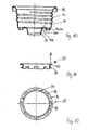
- the insert 14 from the tank neck 12 for replacement or repair removed is to be, is according to the embodiment shown in Figure 10 the level 31 divided by two overlapping in a subarea Sub-stages 31 a, 31 b executed, the detachable arrangement of Use over the separate sub-stages 31a, 31b corresponding to the Figure 6 and 7 described embodiment is formed. So is the lower part 31 a integral part of the from bent flange 18 and from the upper cylinder portion 30th existing section of the neck piece 17, and as far as this Part of the bent flange 18 fixed to the filler neck is connected to the tank, the lower sub-level 31 a is fixed.
- the use 14 becomes in FIGS. 6 and 7 and FIG.
- a reinforcing ring 35 is shown as he in plastic fluid tanks for improving the Connection of the neck piece 17 by means of a screw connection (FIG. 1 to 5) already in the production of the fluid tank 10 in the neck 26th or the tank neck 12 can be integrated.
- the reinforcing ring 35 consists of a wall portion 37 with a at its upper edge circumferential flange 36, and it is so in the manufacture of the Plastic tanks 10 integrated, that the flange 36, the upper edge 13 of the Tank neck 12 forms, while the wall portion 37 the inner Reinforced edge region of the filler neck 12.
- the Reinforcement ring 35 protrude outwardly projecting from the Wall section 37 out bent tabs 38 out.
- In the flange 36 are still holes 39 for receiving the mounting screws 21st formed for the throat 17.
- the insert 14 can be made in two parts be with an outer part 40, which two-stage with a section 41st larger diameter and an adjoining section 42 smaller diameter is formed, wherein between the sections 41, 42 is an inwardly projecting step 43.
- the outer part 40 is an inner part 44th provided with a section 45 of larger diameter and a Section 46 of smaller diameter, where also between the Sections 45 and 46, a step 47 is formed.
- Inner part 44 and Outer part 40 are coordinated so that the two Parts 40, 44 fit into each other with an exact fit. It is the Magnet 48 before inserting the inner part 44 in the section 41st Larger diameter of the outer part 40 inserted so that he on the Level 43 of the outer part 40 superimposed. Will now the inner part 44 in the Inserted outer part 40, so sets the level 47 of the inner part 44 the surface of the magnet 48 so that the magnet between the steps 43 and 47 and, moreover, completely from inner part 44 and Outer part 40 enclosed and thereby held.
- a flange 51 is formed on the upper edge of the outer part 40.
- the insert 14 in a metal existing Tank body is to be used, is on the tank neck 12 of the Metal existing tank body 11 according to Figure 14 of the filler neck 24th placed on the outside and welded to the tank body 11.
- the Filler neck 24 has an inner flange 57, on which the insert 14th superimposed with its outer flange 51, so that a screw by means of screws 56 between the insert 14 and the filler neck 24th can be produced.
- the insert 14 rests with its outer flange 51 on the Inner flange 55 of the Einglall Alns 24, wherein the provided Screw connection over both the outer flange 51 of the insert 14, the inner flange 55 of the filler neck 24 and the reinforcing ring 57th detecting screws 56 may be given.
Landscapes
- Engineering & Computer Science (AREA)
- Life Sciences & Earth Sciences (AREA)
- Sustainable Development (AREA)
- Sustainable Energy (AREA)
- Chemical & Material Sciences (AREA)
- Combustion & Propulsion (AREA)
- Transportation (AREA)
- Mechanical Engineering (AREA)
- Cooling, Air Intake And Gas Exhaust, And Fuel Tank Arrangements In Propulsion Units (AREA)
- Loading And Unloading Of Fuel Tanks Or Ships (AREA)
Abstract
Description
- Fig. 1
- den Tankstutzen eines Fluidtanks mit aufgesetztem Einfüllstutzen und Einbauten im Schnitt für einen Kunststofftank,
- Fig. 2
- die Halterung für den Fehlbetankungseinsatz im Schnitt,
- Fig. 3
- die Halterung gemäß Figur 2 in einer Draufsicht,
- Fig. 4
- die Halterung gemäß Figur 2 in einer anderen Ausführungsform,
- Fig. 5
- die Halterung gemäß Figur 5 in einer Draufsicht,
- Fig. 6
- den Tankstutzen gemäß Figur 1 für einen Metalltank,
- Fig. 7
- den Einfüllstutzen gemäß Figur 6 mit Einbauten in einer Einzeldarstellung,
- Fig. 8
- den Tankstutzen eines Fluidtanks mit einem als Einfüllstutzen ausgebildeten Halsstück im Schnitt,
- Fig. 9
- das als Einfüllstutzen ausgebildete Halsstück gemäß Figur 4 in einer Einzeldarstellung,
- Fig. 10
- den Gegenstand der Figur 9 mit einem lösbaren Einsatz,
- Fig. 11
- ein an dem Fluidtank zu integrierender Verstärkungsring in einer Draufsicht,
- Fig. 12
- der Verstärkungsring gemäß Figur 11 in einer Draufsicht,
- Fig. 13
- ein den Magneten aufnehmender Einsatz in einer auseinander gezogenen, perspektivischen Darstellung,
- Fig. 14
- die Festlegung des Einsatzes an einem bei einem Metall-Tankkorpus verwendeten Einfüllstutzen,
- Fig. 15
- die Festlegung des Einsatzes an einem bei einem Kunststoff-Tankkorpus verwendeten Einfüllstutzen.
Claims (27)
- Vorrichtung zur Vermeidung einer Fehlbetankung bei Kraftfahrzeugen mit einem an dem einen Bestandteil des Tankkorpus (10) bei einem Fluidtank in Kraftfahrzeugen bildenden Tankstutzen (11) anzubringenden Einsatz (14) zur Aufnahme einer an die Formgebung des Einsatzes (14) angepaßten Zapfpistole, wobei der ringförmige Einsatz (14) in seiner Wandung einen die Zapfpistole umschließenden und mit einem in der Zapfpistole angeordneten Schließmechanismus zusammenwirkenden Magneten (15,48) aufnimmt, dadurch gekennzeichnet, daß der in den Tankstutzen (12) einzusetzende Einsatz (14) an einem an dem Tankstutzen (12) des Tankkorpus (11) befestigten Einfüllstutzen (24) auswechselbar gehaltert ist.
- Vorrichtung nach Anspruch 1, dadurch gekennzeichnet, daß der Einsatz (14) an einer als ein mit einer Wandung (19) in den Tankstutzen (12) einzusetzendes und sich mit einem an seinem oberen Ende ausgebildeten umlaufenden Flansch (18) am Tankstutzen (12) abstützendes Halsstück (17) ausgebildeten Halterung gehaltert ist, wobei in einem Bereich des Halsstücks (17) Öffnungen (22) zur Aufnahme von Befestigungsmitteln (23) für eine auswechselbare Halterung des Einsatzes (14) an dem Halsstück (17) ausgebildet sind, und wobei der die Öffnungen (22) aufnehmende Bereich des Halsstücks (17) von dem Tankstutzen (12) lösbar ist.
- Vorrichtung nach Anspruch 2, dadurch gekennzeichnet, daß der obere Flansch (18) des Halsstücks (17) an seinem äußeren umlaufenden Rand einen aufstehenden Rand (27) aufweist und das Halsstück (17) mit einem seinen Rand (27) übergreifenden Einfüllstutzen (24) als Träger eines Verschlußdeckels (25) zu einer auf den Tankstutzen (12) des Tankkorpus (11) aufzusetzenden Baueinheit verbunden ist.
- Vorrichtung nach Anspruch 3, dadurch gekennzeichnet, daß zur Befestigung der aus Halsstück (17) und Einfüllstutzen (24) bestehenden Baueinheit an einem Kunststofftank der obere Flansch (18) des Halsstücks (17) auf dem oberen Rand (13) des Tankstutzens (12) aufsitzt und an dem Rand (13) befestigt ist.
- Vorrichtung nach Anspruch 4, dadurch gekennzeichnet, daß die Befestigung aus einer Schraubverbindung besteht.
- Vorrichtung nach Anspruch 4 oder 5, dadurch gekennzeichnet, daß die Schraubverbindung aus wenigstens einer den Flansch (18) durchgreifenden und stirnseitig in den oberen Rand (13) des Tankstutzens (12) eingeschraubten Schraube besteht.
- Vorrichtung nach Anspruch 3, dadurch gekennzeichnet, daß zur Befestigung der aus Halsstück (17) und Einfüllstutzen (24) gebildeten Baugruppe an einem Metalltank der Einfüllstutzen (24) außenseitig mit dem Tankkorpus (11) verschweißt ist und der Flansch (18) des Halsstücks zweiteilig mit zwei sich in einem Teilbereich überlappenden Teilflanschen (18a, 18b) ausgebildet ist, wobei der eine Teilflansch (18a) über den Rand (27) fest mit dem Einfüllstutzen (24) verbunden ist und der andere Teilflansch (18b) fest mit der den Einsatz (14) umschließenden Wandung (19) verbunden ist, und wobei der den Einsatz (14) tragende Teilflansch (18b) auf dem Teilflansch (18a) auflagert und im Überlappungsbereich lösbar damit verbunden und aus dem Einfüllstutzen (24) entnehmbar ist.
- Vorrichtung nach einem der Ansprüche 2 bis 7, dadurch gekennzeichnet, daß das Halsstück (17) eine zylindrische Form mit einer den Einsatz (14) wenigstens teilweise außen umschließenden Wandung (19) aufweist und die Befestigungsmittel (23) die Wandung (13) des Halsstücks (17) durchstoßen und in die Wandung des Einsatzes (14) hineinreichen.
- Vorrichtung nach einem der Ansprüche 2 bis 7, dadurch gekennzeichnet, daß das Halsstück (17) eine gestufte Form mit einem in seinem Außendurchmesser dem Innendurchmesser des Tankstutzens (12) angepaßten oberen Zylinderabschnitt (30) und mit einem daran unter Ausbildung einer nach Innen einspringenden Stufe (31) anschließenden unteren Zylinderabschnitt (32) mit einem dem zur Aufnahme der Zapfpistole (16) eingerichteten Innendurchmesser des Einsatzes (14) angepaßten Außendurchmesser aufweist derart, daß der Einsatz (14) mit seinem Innendurchmesser auf den unteren Zylinderabschnitt (32) des Halsstücks (17) aufschiebbar ist und die Befestigungsmittel (23) durch im Bereich der Stufe (31) angeordnete Öffnungen (22) stirnseitig in die Wandung des Einsatzes (14) einbringbar sind.
- Vorrichtung nach einem der Ansprüche 2 bis 9, dadurch gekennzeichnet, daß das Halsstück (17) als integraler Einfüllstutzen ausgebildet und in dem oberen Bereich seiner Wandung (19) mit einem Innengewinde (33) zum Einschrauben eines Verschlußdeckels versehen ist.
- Vorrichtung nach Anspruch 9 und 10, dadurch gekennzeichnet, daß das Innengewinde (33) in dem oberen Zylinderabschnitt (30) des als Einfüllstutzen ausgebildeten Halsstücks (17) angeordnet ist.
- Vorrichtung nach Anspruch 10 oder 11, dadurch gekennzeichnet, daß der obere Flansch (18) des als Einfüllstutzen ausgebildeten Halsstücks (17) den oberen Rand (13) des Tankstutzens (12) umgreifend umgebogen und daran befestigt ist.
- Vorrichtung nach Anspruch 12, dadurch gekennzeichnet, daß bei einem Metalltank der umgebogene Flansch (18) des Halsstücks (17) an seinem äußeren Rand außenseitig mit dem Tankstutzen (12) des Tankkorpus (11) verschweißt ist.
- Vorrichtung nach Anspruch 12, dadurch gekennzeichnet, daß bei aus Kunststoff bestehendem Tank der umgebogene Flansch (18) des Halsstücks (17) im Preßsitz mit dem Tankstutzen (12) verbunden ist.
- Halterung nach einem der Ansprüche 10 bis 14, dadurch gekennzeichnet, dass das Halsstück (17) eine Stufe (31) zur Halterung des Einsatzes (14) aufweist, wobei die Stufe (31) mit zwei sich in einem Teilbereich überlappenden Teilstufen (31 a, 31 b) ausgebildet ist, wobei die eine Teilstufe (31a) über den oberen Zylinderabschnitt (30) integraler Bestandteil des umgebogenen Flansches (18) und damit am Tankstutzen (12) festgelegt ist und die andere Teilstufe (31b) den Einsatz (14) trägt, und wobei die Teilstufe (31 b) auf der Teilstufe (31 a) auflagert und im Überlappungsbereich damit lösbar verbunden und aus dem mit dem Tankstutzen fest verbundenen Halsstück (17) entnehmbar ist.
- Aus Kunststoff bestehender Flüssigkeitstank (10) zur Verwendung mit einer nach einem der Ansprüche 1 bis 13 ausgebildeten Halterung (17), bei welchem bei der Herstellung des Kunststofftanks am Tankstutzen (12) ein Verstärkungsring (35) mit einem den oberen Rand (13) des Tankstutzens (12) ausbildenden umlaufenden Flansch (36) und einem in den Tankstutzen (12) hineinreichenden Wandabschnitt (37) in dem Kunststoff eingeschlossen wird, wobei die Befestigung der Halterung (17) an dem Tankstutzen (12) an dem Flansch (36) des Verstärkungsringes (35) ausführbar ist.
- Kunststofftank nach Anspruch 16, dadurch gekennzeichnet, daß der Verstärkungsring (35) auf der Außenseite seines Wandabschnitts (37) mit davon abragenden und in das Kunststoffmaterial hineinragenden Laschen (38) versehen ist.
- Vorrichtung nach Anspruch 1, dadurch gekennzeichnet, daß der Einsatz (14) aus zwei ineinander einschiebbaren Teilen (40, 44) besteht, wobei Außenteil (40) und Innenteil (44) jeweils aus einem zylindrischen Abschnitt mit einem größeren Durchmesser (41, 45) und einem daran anschließenden zylindrischen Abschnitt (42, 46) mit einem geringeren Durchmesser bestehen und Außenteil (40) und Innenteil (44) passgenau ineinander einsteckbar sind, und wobei die Längserstreckung des den größeren Durchmesser aufweisenden zylindrischen Abschnitts (45) des Innenteils (44) zur Ausbildung eines Freiraums im Bereich der zwischen den Abschnitten unterschiedlichen Durchmessers bestehenden Stufen (43, 47) kürzer bemessen ist als die Längserstreckung des zugeordneten Abschnitts (41) des Außenteils (40).
- Vorrichtung nach Anspruch 18, dadurch gekennzeichnet, daß der Magnet (48) in dem zwischen Innenteil (44) und Außenteil (40) im Bereich von deren Stufen (43, 47) gebildeten Freiraum angeordnet ist.
- Vorrichtung nach Anspruch 18 oder 19, dadurch gekennzeichnet, daß an der im Außenteil (40) gebildeten Stufe (43) eine den bei in das Außenteil (40) eingesetztem Innenteil (44) zwischen den ineinandersteckenden Abschnitten (42, 46) mit kleinerem Durchmesser bestehenden Zwischenraum abdichtende Dichtung (49) angeordnet ist, auf der der Magnet (48) auflagert, und daß oberhalb des Magneten (48) auf den Abschnitt (46) kleineren Durchmessers des Innenteils (44) eine weitere Dichtung (50) aufgesteckt ist.
- Vorrichtung nach einem der Ansprüche 18 bis 20, dadurch gekennzeichnet, daß der Einsatz (14) mit einem am oberen Rand seines Außenteils (40) ausgebildeten Flansch (51) auf einem an der Innenseite des Einfüllstutzens (24) ausgebildeten Innenflansch (55) auflagert und mit dem Einfüllstutzen (24) verbunden ist.
- Vorrichtung nach einem der Ansprüche 18 bis 21, dadurch gekennzeichnet, daß in die von Außenteil (40) und Innenteil (44) gemeinsam gebildete Aufnahmeöffnung des Einsatzes (14) ein der Aufnahme der Zapfpistole dienender und die Zapfpistole beim Einstecken führender Schutzeinsatz (52) aus einem hochschlagfesten, temperaturbeständigen Kunststoff eingesetzt ist.
- Vorrichtung nach Anspruch 22, dadurch gekennzeichnet, daß der Schutzeinsatz (52) mit dem am Außenteil (40) des Einsatzes (14) ausgebildeten Flansch (51) im Formschluss verbunden und dadurch am Einsatz (14) festgelegt ist.
- Vorrichtung nach einem der Ansprüche 18 bis 23, dadurch gekennzeichnet, dass bei aus Metall bestehendem Tankkorpus (11) der Einfüllstutzen (24) den Tankstutzen (12) übergreift und außenseitig mit dem Tankkorpus (11) verschweißt ist.
- Vorrichtung nach einem der Ansprüche 18 bis 23, dadurch gekennzeichnet, dass bei einem aus Kunststoff bestehenden Tankkorpus (11) ein Verstärkungsring (57) in den oberen Rand des Tankstutzens (12) eingeschlossen und der auf den Tankstutzen (12) aufgesetzte Einfüllstutzen (24) mit dem Verstärkungsring (57) mittels Verschraubungen (56) verbindbar ist.
- Vorrichtung nach Anspruch 25, dadurch gekennzeichnet, dass der Einfüllstützen (24) mit dem an ihm ausgebildeten Innenflansch (55) auf dem Verstärkungsring (57) des Tankstutzens (12) auflagert und die Verschraubungen (56) unter Einschluss des Einsatzes (14) der Befestigung des Einfüllstutzens (24) auf dem Tankstutzen (12) dienen.
- Vorrichtung nach Anspruch 25 oder 26, dadurch gekennzeichnet, dass zwischen dem Tankstutzen (12) und dem Einfüllstutzen (24) eine zusätzliche Dichtung (58) angeordnet ist.
Applications Claiming Priority (4)
| Application Number | Priority Date | Filing Date | Title |
|---|---|---|---|
| DE20312178U | 2003-08-01 | ||
| DE20312178U DE20312178U1 (de) | 2003-08-01 | 2003-08-01 | Fehlbetankungseinsatz-Halterung für Flüssigkeitstanks an Kraftfahrzeugen |
| DE20315807U | 2003-10-10 | ||
| DE20315807U DE20315807U1 (de) | 2003-10-10 | 2003-10-10 | Fehlbetankungseinsatz-Halterung für Fluidtanks an Kraftfahrzeugen |
Publications (3)
| Publication Number | Publication Date |
|---|---|
| EP1502794A2 true EP1502794A2 (de) | 2005-02-02 |
| EP1502794A3 EP1502794A3 (de) | 2006-05-17 |
| EP1502794B1 EP1502794B1 (de) | 2008-11-12 |
Family
ID=33542409
Family Applications (1)
| Application Number | Title | Priority Date | Filing Date |
|---|---|---|---|
| EP20040017171 Expired - Lifetime EP1502794B1 (de) | 2003-08-01 | 2004-07-21 | Vorrichtung zum Vermeiden einer Fehlbetankung bei Kraftfahrzeugen |
Country Status (2)
| Country | Link |
|---|---|
| EP (1) | EP1502794B1 (de) |
| DE (1) | DE502004008441D1 (de) |
Cited By (13)
| Publication number | Priority date | Publication date | Assignee | Title |
|---|---|---|---|---|
| WO2007006451A1 (de) | 2005-07-13 | 2007-01-18 | Reutter Gmbh | Einfüllstutzen für einen behälter |
| DE202009001182U1 (de) | 2009-01-30 | 2009-04-30 | Jost Automotive Gmbh | Vorrichtung zur Verhinderung einer Fehlbetankung |
| WO2009150149A3 (de) * | 2008-06-09 | 2010-07-22 | Kt Projektentwicklungs-Gmbh | Einsatzelement für einen zur tankstellenseitigen befüllung mit harnstoff geeigneten behälter |
| WO2011029912A1 (de) | 2009-09-11 | 2011-03-17 | Erhard & Söhne GmbH | Behälter zur aufnahme eines kraft- und/oder betriebsstoffes für fahrzeuge |
| WO2011048016A1 (en) | 2009-10-21 | 2011-04-28 | Inergy Automotive Systems Research (Société Anonyme) | Improved filling system for vehicular fluid container |
| WO2012072529A3 (de) * | 2010-12-04 | 2012-07-26 | Reutter Gmbh | Einsatz für einen einfüllstutzen eines harnstoffbehälters |
| DE202011100846U1 (de) * | 2011-05-16 | 2012-08-17 | Reutter Gmbh | Einfüllstutzen für einen Harnstoffbehälter und einen damit versehenen Harnstoffbehälter |
| DE102011113101A1 (de) | 2011-09-09 | 2013-03-14 | Volkswagen Aktiengesellschaft | Einfüllstutzen für ein Fahrzeug |
| US20140110405A1 (en) * | 2011-06-29 | 2014-04-24 | Volkswagen Aktiengesellschaft | Misfuelling prevention device for a filler neck of a fuel tank |
| US20150069058A1 (en) * | 2013-09-06 | 2015-03-12 | Hyundai Motor Company | Misfuelling prevention apparatus for vehicles |
| WO2015167977A1 (en) * | 2014-04-29 | 2015-11-05 | Illinois Tool Works Inc. | Filling device, filling assembly, liquid tank, motor vehicle and implementing method |
| CN114673583A (zh) * | 2020-12-24 | 2022-06-28 | 长城汽车股份有限公司 | 控制方法、装置、存储介质、控制器及车辆 |
| US12085216B2 (en) | 2022-02-17 | 2024-09-10 | Arctic Cat Inc. | Multi-use fuel filler tube |
Family Cites Families (4)
| Publication number | Priority date | Publication date | Assignee | Title |
|---|---|---|---|---|
| DE3425461A1 (de) * | 1984-07-11 | 1986-01-23 | Robert Bosch Gmbh, 7000 Stuttgart | Schutzeinrichtung fuer kraftfahrzeuge |
| US5562133A (en) * | 1994-06-24 | 1996-10-08 | Hiesky Corporation | Fuel dispensing nozzle |
| US5474115A (en) * | 1994-08-04 | 1995-12-12 | Husky Corporation | Specialty fuel dispensing nozzle |
| DE10037824B4 (de) * | 2000-08-03 | 2009-06-10 | Daimler Ag | Vorrichtung zum Verhindern des Einführens einer Zapfpistole |
-
2004
- 2004-07-21 DE DE200450008441 patent/DE502004008441D1/de not_active Expired - Fee Related
- 2004-07-21 EP EP20040017171 patent/EP1502794B1/de not_active Expired - Lifetime
Cited By (27)
| Publication number | Priority date | Publication date | Assignee | Title |
|---|---|---|---|---|
| WO2007006451A1 (de) | 2005-07-13 | 2007-01-18 | Reutter Gmbh | Einfüllstutzen für einen behälter |
| US20110100985A1 (en) * | 2008-06-09 | 2011-05-05 | Kt Projektentwicklungs-Gmbh | Insert element for a container suitable for filling with urea at a filling station |
| WO2009150149A3 (de) * | 2008-06-09 | 2010-07-22 | Kt Projektentwicklungs-Gmbh | Einsatzelement für einen zur tankstellenseitigen befüllung mit harnstoff geeigneten behälter |
| US8800611B2 (en) * | 2008-06-09 | 2014-08-12 | Tecinnovation Gmbh | Insert element for a container suitable for filling with urea at a filling station |
| DE202009001182U1 (de) | 2009-01-30 | 2009-04-30 | Jost Automotive Gmbh | Vorrichtung zur Verhinderung einer Fehlbetankung |
| WO2011029912A1 (de) | 2009-09-11 | 2011-03-17 | Erhard & Söhne GmbH | Behälter zur aufnahme eines kraft- und/oder betriebsstoffes für fahrzeuge |
| DE102009029362A1 (de) | 2009-09-11 | 2011-03-24 | Erhard & Söhne GmbH | Behaelter zur Aufnahme eines Kraft- und/oder Betriebsstoffes fuer Fahrzeuge |
| RU2539615C2 (ru) * | 2009-10-21 | 2015-01-20 | Инержи Отомоутив Системз Рисерч (Сосьете Аноним) | Усовершенствованная система заправки емкости для текучей среды транспортного средства |
| KR20120089689A (ko) * | 2009-10-21 | 2012-08-13 | 이너지 오토모티브 시스템즈 리서치 (소시에떼 아노님) | 차량용 유체 용기를 위한 개선된 충전 시스템 |
| US10576819B2 (en) | 2009-10-21 | 2020-03-03 | Plastic Omnium Advanced Innovation And Research | Filling system for vehicular fluid container |
| EP2316685A1 (de) | 2009-10-21 | 2011-05-04 | Inergy Automotive Systems Research (Société Anonyme) | Verbessertes Füllsystem für Fahrzeugflüssigkeitsbehälter |
| US8919393B2 (en) | 2009-10-21 | 2014-12-30 | Inergy Automotive Systems Research S.A. | Filling system for vehicular fluid container |
| WO2011048016A1 (en) | 2009-10-21 | 2011-04-28 | Inergy Automotive Systems Research (Société Anonyme) | Improved filling system for vehicular fluid container |
| WO2012072529A3 (de) * | 2010-12-04 | 2012-07-26 | Reutter Gmbh | Einsatz für einen einfüllstutzen eines harnstoffbehälters |
| CN103415412A (zh) * | 2010-12-04 | 2013-11-27 | 罗伊特有限公司 | 用于尿素容器的注入连管的嵌件 |
| DE202011100846U1 (de) * | 2011-05-16 | 2012-08-17 | Reutter Gmbh | Einfüllstutzen für einen Harnstoffbehälter und einen damit versehenen Harnstoffbehälter |
| WO2012156292A1 (de) * | 2011-05-16 | 2012-11-22 | Reutter Gmbh | Einfüllstutzen für einen harnstoffbehälter und einen damit versehenen harnstoffbehälter |
| US9272618B2 (en) * | 2011-06-29 | 2016-03-01 | Volkswagen Aktiengesellschaft | Misfuelling prevention device for a filler neck of a fuel tank |
| US20140110405A1 (en) * | 2011-06-29 | 2014-04-24 | Volkswagen Aktiengesellschaft | Misfuelling prevention device for a filler neck of a fuel tank |
| DE102011113101A1 (de) | 2011-09-09 | 2013-03-14 | Volkswagen Aktiengesellschaft | Einfüllstutzen für ein Fahrzeug |
| WO2013034266A1 (de) | 2011-09-09 | 2013-03-14 | Volkswagen Aktiengesellschaft | Einfüllstutzen für ein fahrzeug |
| US20150069058A1 (en) * | 2013-09-06 | 2015-03-12 | Hyundai Motor Company | Misfuelling prevention apparatus for vehicles |
| US9481239B2 (en) * | 2013-09-06 | 2016-11-01 | Hyundai Motor Company | Misfuelling prevention apparatus for vehicles |
| WO2015167977A1 (en) * | 2014-04-29 | 2015-11-05 | Illinois Tool Works Inc. | Filling device, filling assembly, liquid tank, motor vehicle and implementing method |
| CN114673583A (zh) * | 2020-12-24 | 2022-06-28 | 长城汽车股份有限公司 | 控制方法、装置、存储介质、控制器及车辆 |
| CN114673583B (zh) * | 2020-12-24 | 2023-05-12 | 长城汽车股份有限公司 | 车辆加注控制方法、装置、存储介质、控制器及车辆 |
| US12085216B2 (en) | 2022-02-17 | 2024-09-10 | Arctic Cat Inc. | Multi-use fuel filler tube |
Also Published As
| Publication number | Publication date |
|---|---|
| EP1502794A3 (de) | 2006-05-17 |
| DE502004008441D1 (de) | 2008-12-24 |
| EP1502794B1 (de) | 2008-11-12 |
Similar Documents
| Publication | Publication Date | Title |
|---|---|---|
| DE4314923C2 (de) | Verschlußkappe zum Verschließen einer Flasche | |
| EP1502794A2 (de) | Vorrichtung zum Vermeiden einer Fehlbetankung bei Kraftfahrzeugen | |
| EP2102484B1 (de) | Kraftstofffilter eines fahrzeug-verbrennungsmotors | |
| DE3405105C1 (de) | OElbehaelter einer Kunststoff-Spritzgiessmaschine mit einem Luftfilter an einer Druckausgleichsoeffnung | |
| DE69103620T2 (de) | Flüssigkeitsbehälter mit abnehmbarer Verkleidung. | |
| DE102009026516A1 (de) | Werkzeugmaschine, insbesondere Handwerkzeugmaschine | |
| DE202011100846U1 (de) | Einfüllstutzen für einen Harnstoffbehälter und einen damit versehenen Harnstoffbehälter | |
| EP0011780B1 (de) | Verschlussdeckel für Kraftstofftankstutzen von Kraftfahrzeugen | |
| DE2718161C3 (de) | Kraftstoffbehälter für Kraftfahrzeuge, insbesondere für Motorräder | |
| EP0072945A1 (de) | Abschliessbarer Sicherheitsbehälter für Zweiräder | |
| EP1077824B1 (de) | Kraftstoffbehälter | |
| DE4240629A1 (de) | Befestigungsvorrichtung für Einbauteile eines Kunststoff-Flüssigkeitsbehälters, insbesondere des Kraftstoffbehälters eines Kraftfahrzeugs | |
| DE20315807U1 (de) | Fehlbetankungseinsatz-Halterung für Fluidtanks an Kraftfahrzeugen | |
| WO2018050237A1 (de) | Filtereinrichtung, insbesondere luftfilter, für eine frischluftanlage einer brennkraftmaschine | |
| DE20120143U1 (de) | Sprühdose | |
| DE3714890A1 (de) | Behaelter mit nicht abnehmbarem deckel | |
| DE19602819A1 (de) | Kraftstoffbehälter | |
| DE202005004189U1 (de) | Tankstutzen | |
| EP1138540A2 (de) | Einfüllstutzen | |
| EP1106225A1 (de) | Druckwasserfilter | |
| DE20312178U1 (de) | Fehlbetankungseinsatz-Halterung für Flüssigkeitstanks an Kraftfahrzeugen | |
| DE3926821A1 (de) | Spundbehaelter | |
| DE3735105C1 (de) | Demontierbares Kugelgelenk mit Deckeldichtung fuer Kraftfahrzeuge | |
| DE3705072A1 (de) | Luftfilter fuer fahrzeuge | |
| DE8805665U1 (de) | Verschlußkappe aus Kunststoff, insbesondere für Injektions- und Infusionsfläschchen |
Legal Events
| Date | Code | Title | Description |
|---|---|---|---|
| PUAI | Public reference made under article 153(3) epc to a published international application that has entered the european phase |
Free format text: ORIGINAL CODE: 0009012 |
|
| AK | Designated contracting states |
Kind code of ref document: A2 Designated state(s): AT BE BG CH CY CZ DE DK EE ES FI FR GB GR HU IE IT LI LU MC NL PL PT RO SE SI SK TR |
|
| AX | Request for extension of the european patent |
Extension state: AL HR LT LV MK |
|
| PUAL | Search report despatched |
Free format text: ORIGINAL CODE: 0009013 |
|
| AK | Designated contracting states |
Kind code of ref document: A3 Designated state(s): AT BE BG CH CY CZ DE DK EE ES FI FR GB GR HU IE IT LI LU MC NL PL PT RO SE SI SK TR |
|
| AX | Request for extension of the european patent |
Extension state: AL HR LT LV MK |
|
| 17P | Request for examination filed |
Effective date: 20061026 |
|
| 17Q | First examination report despatched |
Effective date: 20061207 |
|
| AKX | Designation fees paid |
Designated state(s): DE ES IT |
|
| GRAP | Despatch of communication of intention to grant a patent |
Free format text: ORIGINAL CODE: EPIDOSNIGR1 |
|
| RAP1 | Party data changed (applicant data changed or rights of an application transferred) |
Owner name: JOST AUTOMOTIVE GMBH |
|
| RIN1 | Information on inventor provided before grant (corrected) |
Inventor name: JOST, INGO |
|
| GRAS | Grant fee paid |
Free format text: ORIGINAL CODE: EPIDOSNIGR3 |
|
| GRAA | (expected) grant |
Free format text: ORIGINAL CODE: 0009210 |
|
| AK | Designated contracting states |
Kind code of ref document: B1 Designated state(s): DE ES IT |
|
| REF | Corresponds to: |
Ref document number: 502004008441 Country of ref document: DE Date of ref document: 20081224 Kind code of ref document: P |
|
| PG25 | Lapsed in a contracting state [announced via postgrant information from national office to epo] |
Ref country code: ES Free format text: LAPSE BECAUSE OF FAILURE TO SUBMIT A TRANSLATION OF THE DESCRIPTION OR TO PAY THE FEE WITHIN THE PRESCRIBED TIME-LIMIT Effective date: 20090223 |
|
| PLBE | No opposition filed within time limit |
Free format text: ORIGINAL CODE: 0009261 |
|
| STAA | Information on the status of an ep patent application or granted ep patent |
Free format text: STATUS: NO OPPOSITION FILED WITHIN TIME LIMIT |
|
| 26N | No opposition filed |
Effective date: 20090813 |
|
| PG25 | Lapsed in a contracting state [announced via postgrant information from national office to epo] |
Ref country code: DE Free format text: LAPSE BECAUSE OF NON-PAYMENT OF DUE FEES Effective date: 20100202 |
|
| PG25 | Lapsed in a contracting state [announced via postgrant information from national office to epo] |
Ref country code: IT Free format text: LAPSE BECAUSE OF FAILURE TO SUBMIT A TRANSLATION OF THE DESCRIPTION OR TO PAY THE FEE WITHIN THE PRESCRIBED TIME-LIMIT Effective date: 20081112 |