EP1503221B1 - Scanning range sensor - Google Patents
Scanning range sensor Download PDFInfo
- Publication number
- EP1503221B1 EP1503221B1 EP04018274A EP04018274A EP1503221B1 EP 1503221 B1 EP1503221 B1 EP 1503221B1 EP 04018274 A EP04018274 A EP 04018274A EP 04018274 A EP04018274 A EP 04018274A EP 1503221 B1 EP1503221 B1 EP 1503221B1
- Authority
- EP
- European Patent Office
- Prior art keywords
- rotary member
- light
- scanning
- rotational axis
- range sensor
- Prior art date
- Legal status (The legal status is an assumption and is not a legal conclusion. Google has not performed a legal analysis and makes no representation as to the accuracy of the status listed.)
- Expired - Lifetime
Links
- 230000003287 optical effect Effects 0.000 claims description 58
- 238000000034 method Methods 0.000 claims description 6
- 206010034972 Photosensitivity reaction Diseases 0.000 description 8
- 230000036211 photosensitivity Effects 0.000 description 8
- 230000008901 benefit Effects 0.000 description 7
- 238000004140 cleaning Methods 0.000 description 4
- 230000003247 decreasing effect Effects 0.000 description 4
- 238000005259 measurement Methods 0.000 description 4
- 239000002245 particle Substances 0.000 description 4
- 239000000428 dust Substances 0.000 description 3
- 239000000463 material Substances 0.000 description 3
- 230000007246 mechanism Effects 0.000 description 3
- 230000004048 modification Effects 0.000 description 3
- 238000012986 modification Methods 0.000 description 3
- 230000002093 peripheral effect Effects 0.000 description 3
- 238000006243 chemical reaction Methods 0.000 description 2
- 238000010586 diagram Methods 0.000 description 2
- 238000009434 installation Methods 0.000 description 2
- 229920003002 synthetic resin Polymers 0.000 description 2
- 239000000057 synthetic resin Substances 0.000 description 2
- 238000004804 winding Methods 0.000 description 2
- 229910052782 aluminium Inorganic materials 0.000 description 1
- XAGFODPZIPBFFR-UHFFFAOYSA-N aluminium Chemical compound [Al] XAGFODPZIPBFFR-UHFFFAOYSA-N 0.000 description 1
- 230000008859 change Effects 0.000 description 1
- 239000000470 constituent Substances 0.000 description 1
- 230000001419 dependent effect Effects 0.000 description 1
- 238000013461 design Methods 0.000 description 1
- 239000006185 dispersion Substances 0.000 description 1
- 230000000694 effects Effects 0.000 description 1
- 230000005611 electricity Effects 0.000 description 1
- 239000000696 magnetic material Substances 0.000 description 1
- 238000012423 maintenance Methods 0.000 description 1
- 229910052751 metal Inorganic materials 0.000 description 1
- 239000002184 metal Substances 0.000 description 1
- 239000013307 optical fiber Substances 0.000 description 1
- 108091008695 photoreceptors Proteins 0.000 description 1
- 230000008569 process Effects 0.000 description 1
- 238000000926 separation method Methods 0.000 description 1
- 230000001360 synchronised effect Effects 0.000 description 1
- 239000012780 transparent material Substances 0.000 description 1
- 230000000007 visual effect Effects 0.000 description 1
Images


Classifications
-
- G—PHYSICS
- G01—MEASURING; TESTING
- G01S—RADIO DIRECTION-FINDING; RADIO NAVIGATION; DETERMINING DISTANCE OR VELOCITY BY USE OF RADIO WAVES; LOCATING OR PRESENCE-DETECTING BY USE OF THE REFLECTION OR RERADIATION OF RADIO WAVES; ANALOGOUS ARRANGEMENTS USING OTHER WAVES
- G01S7/00—Details of systems according to groups G01S13/00, G01S15/00, G01S17/00
- G01S7/48—Details of systems according to groups G01S13/00, G01S15/00, G01S17/00 of systems according to group G01S17/00
- G01S7/481—Constructional features, e.g. arrangements of optical elements
- G01S7/4817—Constructional features, e.g. arrangements of optical elements relating to scanning
-
- G—PHYSICS
- G01—MEASURING; TESTING
- G01C—MEASURING DISTANCES, LEVELS OR BEARINGS; SURVEYING; NAVIGATION; GYROSCOPIC INSTRUMENTS; PHOTOGRAMMETRY OR VIDEOGRAMMETRY
- G01C15/00—Surveying instruments or accessories not provided for in groups G01C1/00 - G01C13/00
- G01C15/002—Active optical surveying means
-
- G—PHYSICS
- G01—MEASURING; TESTING
- G01S—RADIO DIRECTION-FINDING; RADIO NAVIGATION; DETERMINING DISTANCE OR VELOCITY BY USE OF RADIO WAVES; LOCATING OR PRESENCE-DETECTING BY USE OF THE REFLECTION OR RERADIATION OF RADIO WAVES; ANALOGOUS ARRANGEMENTS USING OTHER WAVES
- G01S17/00—Systems using the reflection or reradiation of electromagnetic waves other than radio waves, e.g. lidar systems
- G01S17/02—Systems using the reflection of electromagnetic waves other than radio waves
- G01S17/06—Systems determining position data of a target
- G01S17/42—Simultaneous measurement of distance and other co-ordinates
-
- G—PHYSICS
- G01—MEASURING; TESTING
- G01S—RADIO DIRECTION-FINDING; RADIO NAVIGATION; DETERMINING DISTANCE OR VELOCITY BY USE OF RADIO WAVES; LOCATING OR PRESENCE-DETECTING BY USE OF THE REFLECTION OR RERADIATION OF RADIO WAVES; ANALOGOUS ARRANGEMENTS USING OTHER WAVES
- G01S7/00—Details of systems according to groups G01S13/00, G01S15/00, G01S17/00
- G01S7/48—Details of systems according to groups G01S13/00, G01S15/00, G01S17/00 of systems according to group G01S17/00
- G01S7/481—Constructional features, e.g. arrangements of optical elements
- G01S7/4811—Constructional features, e.g. arrangements of optical elements common to transmitter and receiver
- G01S7/4813—Housing arrangements
-
- G—PHYSICS
- G01—MEASURING; TESTING
- G01S—RADIO DIRECTION-FINDING; RADIO NAVIGATION; DETERMINING DISTANCE OR VELOCITY BY USE OF RADIO WAVES; LOCATING OR PRESENCE-DETECTING BY USE OF THE REFLECTION OR RERADIATION OF RADIO WAVES; ANALOGOUS ARRANGEMENTS USING OTHER WAVES
- G01S17/00—Systems using the reflection or reradiation of electromagnetic waves other than radio waves, e.g. lidar systems
- G01S17/88—Lidar systems specially adapted for specific applications
- G01S17/93—Lidar systems specially adapted for specific applications for anti-collision purposes
- G01S17/931—Lidar systems specially adapted for specific applications for anti-collision purposes of land vehicles
Definitions
- the present invention relates to so-called scanning range sensors, which use a rotating or vibrating mirror or an equivalent to scan an object with a light beam within a predetermined angle range, and which receive light reflected by the object.
- U.S. Patent No. 5,808,727 discloses a vehicle optical radar apparatus with a light source for emitting a light-sending beam and a light-receiving element for receiving reflection light of a light-sending beam reflected from an object.
- the light source is arranged on one end side of a hollow rotational drive shaft of an actuator, i.e. pulse motor and the light-receiving element is arranged on the other end face side of the hollow rotational drive shaft.
- the apparatus further comprises a light-sending mirror for reflecting the light sending beam to irradiate the object and a light-receiving mirror for reflecting the reflected light and focusing the reflected light on the light-receiving element.
- the light-sending mirror and the light-receiving mirror are arranged on the same end face side of the rotational drive shaft of the actuator.
- the actuator drives the light-sending mirror and the light-receiving mirror synchronously and rotatably, thereby detecting a distance to the object on the basis of a light-sending signal from the light source and a light-receiving signal from the light-receiving element.
- a scanning range sensor that uses a rotating mirror for deflecting the axis of an optical beam over a full, 360-degree range of angles. Both configurations have a mirror whose optical axis coincides with the axis of a motor for rotating the mirror.
- the configuration shown in Fig. 5 uses a motor 52 having rotary shafts 51a and 51b that constitute a common shaft and extend upward and downward, respectively.
- a scanning mirror 53 and a reflecting mirror 54 are attached to respective shafts 51a and 51b so as to have identical phase.
- At numeral 55 in Fig. 5 is a light transmitter
- at numeral 56 is a photodetector
- at numerals 57 and 58 are lenses
- at numeral 63 is a light exit/entrance window 63.
- the sensor section of the scanning range sensor configuration shown in Fig. 6 has a motor 52 with a rotary shaft 51c protruding upward and a light scanning/reflecting mirror 59 that is attached to the rotary shaft 51c.
- Light from the light transmitter 55 passes through a lens 60, is reflected downward by a half-silvered mirror 61, and enters the scanning/reflecting mirror 59.
- This reflected light is reflected by the scanning/reflecting mirror 59, passes through the half-silvered mirror 61, passes through a lens 62, and enters the photodetector 56.
- the motor 52 is positioned between the scanning mirror 53 and the reflecting mirror 54, the distance between the optical axes of the scanning optics and the receiving optics is large. Therefore, if a target object is positioned within close range, light reflected from the object does not enter the photodetector 56, resulting in the occurrence of a blind spot.
- the center of the two optical systems is coincident with the center of the sensor. Therefore, when installing the vertically elongate sensor in a device, its center must be the optical axis. This limits the degrees of freedom for installation in a device.
- a drawback is that the outward-extending portions are large.
- the half-silvered mirror 61 is employed to make the optical axes of the scanning optics and the receiving optics identical to each other.
- the amount of light is reduced by half after being separated by the half-silvered mirror 61. Therefore, the power of the laser in the light transmitter 55, and the amplifying capability of the photodetector 56 must be enhanced by four times in total compared with an implementation in which the scanning optics and the receiving optics are separated as shown in Fig. 5 .
- the fact that the single scanning/reflecting mirror 59 is used means that the scanning beam may be reflected by the inner surface of, or by dust particles on, the light exit/entrance window 63, in which case the stray reflected light can enter the photodetector 56 after being transmitted by the scanning/reflecting mirror 59 and passing through the half-silvered mirror 61. If the photodetector 56 is of enhanced photosensitivity, the stray reflected light may generate noise that becomes added to image information. Consequently, the photosensitivity cannot be heightened without compensating for it.
- An object of the present invention is to shorten the distance between the optical axis of the beam projected from a scanning range sensor toward an object and the optical axis of light reflected by the object into the sensor, thus to make it possible to prevent the sensor from having a blind spot even when the distance from the sensor to the object is short.
- Another object of the present invention is to separate the scanning optical system from the receiving optical system, thus to make it possible to prevent the sensor from being disturbed by noise due to stray light reflected by the transmitting and receiving windows or by dust particles on the transmitting and receiving windows, to allow the photosensitivity of the sensor to be enhanced.
- the scanning range sensor has a structure including: a light receiving section situated on or near a stationary shaft of the motor, in a location where the center of the light receiving section coincides with the rotational axis of the motor; a rotary component having, surrounding the light receiving section, an top wall portion and a circumferential wall potion; and a motor drive mechanism for driving the rotary component.
- a scanning optical system for generating a scanning beam directed on the sensing target, and a receiving optical system for guiding to the light receiving section light reflected by the object are provided individually on the top wall portion of the rotary component.
- the scanning mirror and the reflecting mirror are constructed as entities separate from each other.
- scanning and receiving windows are provided along and in the circumferential wall potion of the rotary component for passing the scanning beam and the reflected light.
- the top wall portion and the circumferential wall portion not only may be walls constituted by boards having a close-packed structure, but also, for example, by mesh constructed with support columns extending along the rotational axis and radially.
- Another embodiment of a scanning sensor according to the present invention has the following structure in addition to the above structure. Namely, image signals obtained by the light receiving section go through space inside the stationary shaft of the motor and are led to an external computation circuit. Then, in order to calculate the position or related information on the object from the image signal, a motor rotational position signal is also led to the external computation circuit via the inside of the motor stationary shaft.
- the scanning mirror and the reflecting mirror are configured for being connected directly to the rotary shaft of the motor as shown in Fig. 5 and Fig. 6 .
- Adopting a configuration according to the present aspect of the invention makes it possible to dispose the photodetector and the light projector to one side of the motor without using a half-silvered mirror.
- the scanning and receiving optical systems can be integrated, while a scanning range sensor in which the distance between the optical axis of the beam projected from the sensor toward an object and the optical axis of light reflected by the object into the sensor is short can be realized.
- the light receiving section can be structured by disposing a photoelectric conversion element where the light receiving section is situated, or by collecting the received light and through an optical fiber or the like sending the collected light to another unit for carrying out photoelectric conversion and other processes.
- a representative application of a scanning sensor according to the present invention is as a visual sensor for a robot or the like.
- the scanning optical axis and the receiving optical axis extend substantially horizontally.
- the motor rotary shaft on the other hand extends substantially vertically. At least the light reflected by the reflecting mirror is guided along the rotational axis of the motor to the light receiving section.
- the scanning beam is emitted by the light projector (a light source) provided separately and is guided along the rotational axis of the motor so that the scanning mirror disposed on the top wall portion of the rotary component converts the orientation of the scanning beam into substantially horizontal.
- the present invention has the following effects.
- a vertically cylindrical outer cover 1 houses a main body of a scanning range sensor.
- the outer cover 1 is placed on the top of the head portion of the robot.
- the outer cover 1 is made of an appropriate material such as a synthetic resin.
- a transparent window 2 that has a horizontally annular form and a uniform vertical width is formed slightly above center.
- This transparent window 2 may be made of a transparent, annularly seamless, band-shaped constituent separate from the main material of the outer cover 1 and set into position as the transparent window.
- the outer cover 1 itself may be formed integrally of a transparent material, and then a portion except for the transparent window may be painted. Note that it is possible to make the entire of the outer cover 1 transparent so that the area of the transparent window is widened to the entirety. In that case, however, it would be necessary to prevent undesired external light from entering the photodetector.
- a light projector 3 is arranged at a position adjacent to the inner surface of the circumferential wall of the outer cover 1 so as to project light vertically upward.
- This light projector 3 has a light source such as a laser or an LED.
- An optical lens 4 for making the diameter of the beam constant is disposed at the upper end of the light projector 3.
- a first mirror 5 is fixed to the inner surface of the top plate 1a of the outer cover 1 and is positioned right above the light projector 3, while a second mirror 6 is fixed to the center position of the inner surface of the same top plate 1a.
- These mirrors 5 and 6 are arranged so that the first mirror 5 is inclined to the right ⁇ in terms of the orientation of the drawing ⁇ approximately 45 degrees from the vertical direction and the second mirror 6 is inclined to the left approximately 45 degrees.
- a cylindrical rotary member 10 is disposed in the outer cover 1 at a position shifted a little to the right in the Fig. 1 representation.
- This cylindrical rotary member 10 is made of an appropriate material such as a synthetic resin, and a light receiving window 11 having a circular shape is formed at an upper portion of the circumferential wall.
- An optical lens 12 is fixed into this light receiving window 11 and is adjusted so that its optical axis coincides with the radius there of the cylindrical rotary member 10.
- the lower portion of the cylindrical rotary member 10 has a rotating-member lower end portion 10b that has a reduced outer diameter. Meanwhile, a motor 15 is disposed in the bottom portion of the outer cover 1.
- This motor 15 includes a stator 15a having a winding coil and a core, a cylindrical portion 16 along the inner circumferential surface of which the stator 15a is fixed, a base plate portion 17 that is disposed in parallel with the bottom portion of the outer cover so as to form an inner bottom surface of the cylindrical portion 16, a motor stationary shaft 19 that is formed in the center of the base plate portion 17, and a horizontal disk portion 20 that is fixed to the upper end of the stationary shaft 19.
- a hollow through-hole 18 is proved inside the motor stationary shaft 19 so as to extend in the vertical direction.
- An inner circumferential surface of a bearing 21 is fixedly fitted to an outer cylindrical surface of the motor stationary shaft 19, and an inner cylindrical surface of the rotating-member lower end portion 10b of the cylindrical rotary member 10 is rotatably engaged with the outer circumferential surface of the bearing 21.
- the bearing 21 can be a ball bearing or a slide bearing, for example.
- magnets 22 are attached to the outside cylindrical surface of the rotary member lower end portion 10b so as to face the stator 15a via a slight gap.
- An external power source (not shown) supplies the stator 15a with a switching current so that a rotating magnetic field is generated in the stator's inner cylindrical space.
- This rotating magnetic field and the magnets 22 that are disposed at the lower end outer circumferential portion of the cylindrical rotary member 10 are attracted by each other, wherein a rotary drive force is generated between them.
- this motor is not limited to being a brushless DC motor but may be a synchronous motor or the like.
- a photodetector 25 is disposed along the rotational axis of the motor on the upper surface of the disk portion 20 as shown in Figs. 1 and 3 .
- This photodetector 25 is constituted by an optical sensor such as a photodiode, and the focal point of the optical lens 12 is adjusted to lie on the photodetector 25.
- the photodetector 25 is connected via a signal wire 26 to a distance computation circuit 27 that is disposed outside the outer cover 1 (in a control portion of the guarding robot or cleaning robot).
- a resolver 28 is arranged surrounding the photodetector 25 on the upper surface of the disk portion 20 for detecting precisely the rotational angle of the cylindrical rotary member 10.
- This resolver 28 includes: an undulating surface 28a as a rotor, made of a magnetic material and being, e.g., four smooth contours formed along the circuit of the inner circumferential surface of the cylindrical rotary member 10; and a resolver stator 28b opposed to the undulating surface 28a and having windings along the upper outer circumferential surface of the disk portion 20.
- an undulating surface 28a as a rotor, made of a magnetic material and being, e.g., four smooth contours formed along the circuit of the inner circumferential surface of the cylindrical rotary member 10
- a resolver stator 28b opposed to the undulating surface 28a and having windings along the upper outer circumferential surface of the disk portion 20.
- a simpler rotational position detector can be realized by providing a mechanism for generating a pulse per rotation of the cylindrical rotary member, and by dividing the pulse signal using a PLL circuit. In that case, the resolver 28 would not be necessary.
- the mechanism for generating the pulse may be realized by providing a Hall sensor at a position that is adjacent to the magnet 22 on the base plate portion 17 or by placing a photoreceptor in the vicinity of the transparent window 2 for the transmitted light, for example.
- a scanning mirror 30 and a reflecting mirror 31 are attached to the top plate portion 10a of the cylindrical rotary member 10 so that the optical axes thereof coincide with the rotational axis.
- the scanning mirror 30 and the reflecting mirror 31 are disposed so as to incline respectively to the left and the right by approximately 45 degrees each from the vertical.
- the beam from the light projector 3 is reflected by the second mirror 6 downward and is incident on the scanning mirror 30 with the optical axis coincident with the rotational axis. Then, the reflected light is radiated substantially in the horizontal direction, to outside the cylindrical rotary member 10 in the radial direction.
- the scanning mirror 30 rotates at a high speed together with the cylindrical rotary member 10. Therefore, a beam having been projected by the light projector 3 and reflected by the scanning mirror 30 after passing through the first mirror 5 and the second mirror 6 is scanned continuously over the entire circuit of peripheral space through the transparent window 2 in the outer cover 1, so as to scan external objects continuously. Then, the light reflected by the objects enters the outer cover 1 through the transparent window 2 to be incident on the reflecting mirror 31 substantially in the horizontal direction after passing through the optical lens 12 in the light receiving window 11.
- the light is reflected downward along the rotational axis by the reflecting mirror 31, and is focused on the photodetector 25, which converts quanta of the light into an electric signal (a phase signal).
- This electric signal is sent to the distance computation circuit 27 via the signal wire 26.
- the resolver 28b detects the rotational angle of the cylindrical rotary member 10 when the photodetector 25 receives the light, and information on the rotational angle is also sent to the distance computation circuit 27 via the signal wire 26.
- the distance computation circuit 27 calculates the distance to the objects in accordance with the phase signal and generates a plane two-dimensional map by combining the distance and the rotational angle information from the resolver 28.
- a scanning range sensor can be realized that has an outer shape much smaller and more compact than the conventional one by the effective and close arrangement of the motor and the optical system.
- the light projector is disposed inside the outer cover, and the beam from the light projector is reflected by the mirror on the inner surface of the outer cover so as to enter the scanning mirror of the rotary member along the direction of the rotational axis.
- the scanning optics is completely separate from the receiving optics, so that reflected light arising in the scanning optics does not enter the receiving optics. This configuration is advantageous for allowing photosensitivity to be increased.
- the scanning angle of the beam must be precisely detected scanning over 360 degrees.
- polar teeth are provided on the cylindrical rotary member of the resolver for detecting the rotational angle, and the stator of the resolver is supported together with the photodetector.
- the rotational angle of the cylindrical rotary member can be detected precisely, and the cylindrical rotary member has only optical elements such as its mirror and polar teeth of the resolver, which do not require electricity. Therefore, durability and reliability of the range sensor can be improved substantially.
- FIG. 4 This example is a variation in which the light projector 3 is arranged on the disk portion 20 inside the cylindrical rotary member 10. Because a half-silvered mirror 35 is used, if a laser is used as a light source, the photosensitivity must be limited for safety by restricting the output power. On the other hand, however, a significant advantage to this configuration is that the vertical height of the scanning range sensor can be further decreased because it is possible to eliminate the mirrors 5 and 6 on the inner surface of the outer cover 1 shown in Fig. 1 . In Fig.
- the beam reflected upward by the half-silvered mirror 35 is incident upon the lower surface of the scanning mirror 36 through a tiny optical through-hole 37 in the center of the reflecting mirror 31, and a tiny optical through-hole 38 in the center of the top plate portion 10a of the cylindrical rotary member 10 along the rotational axis of the cylindrical rotary member 10.
- the scanning mirror 36 is inclined to the right of the vertical by approximately 45 degrees, so that a beam incident on the scanning mirror 36 from directly below is reflected substantially in the horizontal direction to exit the transparent window 2.
- the remainder of the configuration is similar to that shown in Fig. 1 .
- a beam from the light projector 3 passes through the half-silvered mirror 35, the optical through-hole 37 and the optical through-hole 38, is deflected by the scanning mirror 36 and passes through the transparent window 2 to enter peripheral space; meanwhile light reflected from objects passes through the transparent window 2 and the optical lens 12, is reflected by the reflecting mirror 31 and passes through the half-silvered mirror 35 to be received by the photodetector 25.
- Generation of the two-dimensional map after that is the same as described above with reference to Fig. 1 .
- the photosensitivity is lowered a little because a half-silvered mirror is used.
- the scanning light and receiving light are separated from each other, there is no possibility that an inwardly reflected component of the scanning light will enter the photodetector.
- the range sensor can be made more compact because the light projector is disposed inside the cylindrical rotary member.
- the height of the range sensor can be further decreased because it is not necessary to attach a mirror to the inside of the outer cover.
- the above-described light projector typically uses a laser as the light source, it is possible to use an LED as the light source.
- a laser has little dispersion of light, and thus can pass through a narrow path easily. Therefore, the shape of the sensor can be minimized.
- an LED instead of a laser, it is better to use an LED that can be modulated at high frequency.
- An LED is more advantageous than a laser because an LED has a larger light spot than a laser, which is limited in power for safety reasons.
- the AM modulation method is a method in which laser light or LED light is modulated at a constant frequency, and the distance is determined from the difference between the phase of the modulated signal and the phase of light reflected by an object. Namely, if a beam that is modulated at a frequency f is reflected by an object and comes back, the return beam will have a phase difference ⁇ that is determined by the speed of light and the distance. The value of the phase difference ⁇ depends on the speed of light c and the distance L. Therefore, if the phase difference ⁇ is detected, the distance L can be determined.
- distance measurements within a two-dimensional area can be performed.
- the present invention can be applied to a two-dimensional range sensor.
- distance measurements within a three-dimensional region are also possible by scanning the scanning beam over a 360-degree circuit while continuously increasing or decreasing the vertical angle of the scanning mirror.
- peripheral space may be scanned by the beam in a helical fashion, for example.
- a scanning range sensor of the present invention is not limited to these embodiments, but various modifications can be added to the examples within the scope of the present invention as defined by the appended claims.
- the motors in the foregoing embodiments are considered to rotate in one direction at a constant speed, it is possible to control the motor 15 to rotate reversibly within a predetermined angle range.
- the range sensor scans an object only through a predetermined span that is an extension of the outer circumference. Furthermore, it is possible to realize wide angle scanning over a wide range vertically, i.e., three-dimensional scanning, by inclining and vibrating the entire sensor including the outer cover 1 around the rotational axis of the motor 15 with a predetermined periodicity.
Landscapes
- Engineering & Computer Science (AREA)
- Physics & Mathematics (AREA)
- General Physics & Mathematics (AREA)
- Radar, Positioning & Navigation (AREA)
- Remote Sensing (AREA)
- Computer Networks & Wireless Communication (AREA)
- Electromagnetism (AREA)
- Optical Radar Systems And Details Thereof (AREA)
- Measurement Of Optical Distance (AREA)
Description
- The present invention relates to so-called scanning range sensors, which use a rotating or vibrating mirror or an equivalent to scan an object with a light beam within a predetermined angle range, and which receive light reflected by the object.
- Scanning range sensors that are operated according to the above mentioned principle have recently become known. For example,
U.S. Patent No. 5,808,727 discloses a vehicle optical radar apparatus with a light source for emitting a light-sending beam and a light-receiving element for receiving reflection light of a light-sending beam reflected from an object. The light source is arranged on one end side of a hollow rotational drive shaft of an actuator, i.e. pulse motor and the light-receiving element is arranged on the other end face side of the hollow rotational drive shaft. The apparatus further comprises a light-sending mirror for reflecting the light sending beam to irradiate the object and a light-receiving mirror for reflecting the reflected light and focusing the reflected light on the light-receiving element. The light-sending mirror and the light-receiving mirror are arranged on the same end face side of the rotational drive shaft of the actuator. The actuator drives the light-sending mirror and the light-receiving mirror synchronously and rotatably, thereby detecting a distance to the object on the basis of a light-sending signal from the light source and a light-receiving signal from the light-receiving element. - Further, there are two different configurations, as shown respectively in
Figs. 5 and6 , known as a scanning range sensor that uses a rotating mirror for deflecting the axis of an optical beam over a full, 360-degree range of angles. Both configurations have a mirror whose optical axis coincides with the axis of a motor for rotating the mirror. - The configuration shown in
Fig. 5 uses amotor 52 havingrotary shafts scanning mirror 53 and a reflectingmirror 54 are attached torespective shafts numeral 55 inFig. 5 is a light transmitter, atnumeral 56 is a photodetector, atnumerals numeral 63 is a light exit/entrance window 63. There are two advantages to this configuration. One is that there is little diffraction of light from the scanning optics to the receiving optics, because the scanning optics and the receiving optics are completely separate from each other. Another advantage is that the photosensitivity of the sensor can be raised because there is no possibility of stray light being reflected by the inner surface of, or by dust particles on, the exit/entrance window 63 and then entering thephotodetector 56. - The sensor section of the scanning range sensor configuration shown in
Fig. 6 has amotor 52 with arotary shaft 51c protruding upward and a light scanning/reflectingmirror 59 that is attached to therotary shaft 51c. Light from thelight transmitter 55 passes through alens 60, is reflected downward by a half-silvered mirror 61, and enters the scanning/reflectingmirror 59. This reflected light is reflected by the scanning/reflectingmirror 59, passes through the half-silvered mirror 61, passes through alens 62, and enters thephotodetector 56. There are two advantages to this configuration. One is that there is no blind spot for an object even at a close distance from the sensor because onemirror 59 is used in common for both the scanning and the reflecting mirror. Another advantage is that when the sensor is installed in a device such as a robot, a high flexibility in installation can be obtained, for the reason just given. - However, there are some drawbacks to the configuration shown in
Fig. 5 . - First, since the
motor 52 is positioned between thescanning mirror 53 and the reflectingmirror 54, the distance between the optical axes of the scanning optics and the receiving optics is large. Therefore, if a target object is positioned within close range, light reflected from the object does not enter thephotodetector 56, resulting in the occurrence of a blind spot. - Secondly, the fact that the scanning and receiving optics are situated respectively above and below the motor renders the sensor as a unit elongate vertically. Meanwhile, the center of the two optical systems is coincident with the center of the sensor. Therefore, when installing the vertically elongate sensor in a device, its center must be the optical axis. This limits the degrees of freedom for installation in a device. In particular, if the sensor is to be installed in a low-profile device, a drawback is that the outward-extending portions are large.
- In addition, there are a few drawbacks to the configuration shown in
Fig. 6 . - First, the half-
silvered mirror 61 is employed to make the optical axes of the scanning optics and the receiving optics identical to each other. However, the amount of light is reduced by half after being separated by the half-silvered mirror 61. Therefore, the power of the laser in thelight transmitter 55, and the amplifying capability of thephotodetector 56 must be enhanced by four times in total compared with an implementation in which the scanning optics and the receiving optics are separated as shown inFig. 5 . - Secondly, the fact that the single scanning/reflecting
mirror 59 is used means that the scanning beam may be reflected by the inner surface of, or by dust particles on, the light exit/entrance window 63, in which case the stray reflected light can enter thephotodetector 56 after being transmitted by the scanning/reflectingmirror 59 and passing through the half-silvered mirror 61. If thephotodetector 56 is of enhanced photosensitivity, the stray reflected light may generate noise that becomes added to image information. Consequently, the photosensitivity cannot be heightened without compensating for it. - An object of the present invention is to shorten the distance between the optical axis of the beam projected from a scanning range sensor toward an object and the optical axis of light reflected by the object into the sensor, thus to make it possible to prevent the sensor from having a blind spot even when the distance from the sensor to the object is short.
- Another object of the present invention is to separate the scanning optical system from the receiving optical system, thus to make it possible to prevent the sensor from being disturbed by noise due to stray light reflected by the transmitting and receiving windows or by dust particles on the transmitting and receiving windows, to allow the photosensitivity of the sensor to be enhanced.
- In order to achieve these objects, a scanning range sensor having the features of
Claim 1 is proposed. Preferred embodiments are recited in the dependent claims. - According to an embodiment of the present invention the scanning range sensor has a structure including: a light receiving section situated on or near a stationary shaft of the motor, in a location where the center of the light receiving section coincides with the rotational axis of the motor; a rotary component having, surrounding the light receiving section, an top wall portion and a circumferential wall potion; and a motor drive mechanism for driving the rotary component. In addition, a scanning optical system for generating a scanning beam directed on the sensing target, and a receiving optical system for guiding to the light receiving section light reflected by the object are provided individually on the top wall portion of the rotary component. As an example of the specific means for realizing the separation of the scanning and receiving optics, the scanning mirror and the reflecting mirror are constructed as entities separate from each other. In addition, scanning and receiving windows are provided along and in the circumferential wall potion of the rotary component for passing the scanning beam and the reflected light.
- In this embodiment, the top wall portion and the circumferential wall portion not only may be walls constituted by boards having a close-packed structure, but also, for example, by mesh constructed with support columns extending along the rotational axis and radially.
- Another embodiment of a scanning sensor according to the present invention has the following structure in addition to the above structure. Namely, image signals obtained by the light receiving section go through space inside the stationary shaft of the motor and are led to an external computation circuit. Then, in order to calculate the position or related information on the object from the image signal, a motor rotational position signal is also led to the external computation circuit via the inside of the motor stationary shaft.
- In a conventional scanning sensor configuration, the scanning mirror and the reflecting mirror are configured for being connected directly to the rotary shaft of the motor as shown in
Fig. 5 andFig. 6 . For this reason, there was no alternative to separating the scanning optical system from the receiving optical system on the upper and the lower sides of the motor, or to integrating them by using a half-silvered mirror. Adopting a configuration according to the present aspect of the invention makes it possible to dispose the photodetector and the light projector to one side of the motor without using a half-silvered mirror. Thus, the scanning and receiving optical systems can be integrated, while a scanning range sensor in which the distance between the optical axis of the beam projected from the sensor toward an object and the optical axis of light reflected by the object into the sensor is short can be realized. It should be understood that the light receiving section can be structured by disposing a photoelectric conversion element where the light receiving section is situated, or by collecting the received light and through an optical fiber or the like sending the collected light to another unit for carrying out photoelectric conversion and other processes. - In addition, a representative application of a scanning sensor according to the present invention is as a visual sensor for a robot or the like. Therein, the scanning optical axis and the receiving optical axis extend substantially horizontally. The motor rotary shaft on the other hand extends substantially vertically. At least the light reflected by the reflecting mirror is guided along the rotational axis of the motor to the light receiving section. Meanwhile, the scanning beam is emitted by the light projector (a light source) provided separately and is guided along the rotational axis of the motor so that the scanning mirror disposed on the top wall portion of the rotary component converts the orientation of the scanning beam into substantially horizontal.
- According to this configuration, the present invention has the following effects.
- (1) Since the scanning mirror is separated completely from the reflecting mirror, it is possible to prevent diffraction of light and undesired reflection of light due to dirt particles on the light transmitting and receiving windows, which allows the photosensitivity of the sensor to be maximally enhanced. In particular, when scanning using a laser, a limitation on the power of the light source in the light projector is that it cannot be increased over a predetermined value for assuring safety to the human eye. Therefore, it is a significant advantage that the sensing distance can be increased over what has been conventional using a light source of the same power.
- (2) In addition, the scanning optical axis of the beam from the sensor toward an object and the receiving optical axis of light reflected by the object into the sensor can be close to each other. Therefore, a size of the blind spot can be decreased to a extent such that it presents no problems in practical use even if a target object is close to the sensor.
- (3) The scanning mirror and the reflecting mirror are disposed on the same side with respect to the photodetector along the rotational axis of the motor. Therefore, there is high flexibility for placing the sensor inside a device. Especially in the case of a robot or an automatic guided vehicle (AGV) having a low profile, the position of objects can be detected omnidirectionally with merely a tip portion of the sensor extended from the device. Therefore, this is an advantageous form for a sensor when the sensor is used in a cleaning robot that moves around freely under chairs and tables.
- (4) What are disposed on the rotary, moving component are only such optical elements as the scanning mirror, the reflecting mirror, and a rotational-angle detecting device such as an encoder or a resolver. Thus it is unnecessary to mount any electrical devices, such as a light receiving element, on the rotary component. Therefore, a design with high reliability can be implemented, and maintenance is facilitated.
- (5) Optical systems and the photodetector as necessary for the scanning range sensor can be located efficiently within the motor. Therefore, a very small and compact sensor can be realized.
- (6) Wires for output signals of from photodetector and the rotational position detector can be led to an external distance computation circuit via a through-hole inside the stationary shaft of the motor, so a very small and compact outer form can be realized compared with what has been conventional.
- From the following detailed description in conjunction with the accompanying drawings, the foregoing and other objects, features, aspects and advantages of the present invention will become readily apparent to those skilled in the art.
-
-
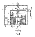
Fig. 1 is a vertical cross section of a scanning range sensor according to the present invention; -
Fig. 2 is a perspective view of the outer form of the scanning range sensor according to the present invention; -
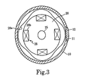
Fig. 3 is a horizontal cross section of a cylindrical rotary member of the scanning range sensor according to the present invention; -
Fig. 4 is a vertical cross section of a scanning range sensor according to a modification of the present invention; -
Fig. 5 is an idealized diagram of a conventional scanning range sensor; and -
Fig. 6 is an idealized diagram of another conventional scanning range sensor. - Hereinafter, three embodiments of the present invention will be described with reference to the attached drawings.
- First,
Figs. 1-3 show a first example of the present invention. In this example, a vertically cylindricalouter cover 1 houses a main body of a scanning range sensor. When using the scanning range sensor of the present invention for a guarding robot or a cleaning robot, theouter cover 1 is placed on the top of the head portion of the robot. Theouter cover 1 is made of an appropriate material such as a synthetic resin. As indicated inFigs. 1 and2 , midway height-wise along the circumferential wall of theouter cover 1, atransparent window 2 that has a horizontally annular form and a uniform vertical width is formed slightly above center. Thistransparent window 2 may be made of a transparent, annularly seamless, band-shaped constituent separate from the main material of theouter cover 1 and set into position as the transparent window. Alternatively, theouter cover 1 itself may be formed integrally of a transparent material, and then a portion except for the transparent window may be painted. Note that it is possible to make the entire of theouter cover 1 transparent so that the area of the transparent window is widened to the entirety. In that case, however, it would be necessary to prevent undesired external light from entering the photodetector. - As shown in
Fig. 1 , inside theouter cover 1, alight projector 3 is arranged at a position adjacent to the inner surface of the circumferential wall of theouter cover 1 so as to project light vertically upward. Thislight projector 3 has a light source such as a laser or an LED. Anoptical lens 4 for making the diameter of the beam constant is disposed at the upper end of thelight projector 3. A first mirror 5 is fixed to the inner surface of the top plate 1a of theouter cover 1 and is positioned right above thelight projector 3, while asecond mirror 6 is fixed to the center position of the inner surface of the same top plate 1a. Thesemirrors 5 and 6 are arranged so that the first mirror 5 is inclined to the right―in terms of the orientation of the drawing―approximately 45 degrees from the vertical direction and thesecond mirror 6 is inclined to the left approximately 45 degrees. - A
cylindrical rotary member 10 is disposed in theouter cover 1 at a position shifted a little to the right in theFig. 1 representation. This cylindricalrotary member 10 is made of an appropriate material such as a synthetic resin, and alight receiving window 11 having a circular shape is formed at an upper portion of the circumferential wall. Anoptical lens 12 is fixed into thislight receiving window 11 and is adjusted so that its optical axis coincides with the radius there of thecylindrical rotary member 10. The lower portion of thecylindrical rotary member 10 has a rotating-memberlower end portion 10b that has a reduced outer diameter. Meanwhile, amotor 15 is disposed in the bottom portion of theouter cover 1. Thismotor 15 includes astator 15a having a winding coil and a core, acylindrical portion 16 along the inner circumferential surface of which thestator 15a is fixed, abase plate portion 17 that is disposed in parallel with the bottom portion of the outer cover so as to form an inner bottom surface of thecylindrical portion 16, a motorstationary shaft 19 that is formed in the center of thebase plate portion 17, and ahorizontal disk portion 20 that is fixed to the upper end of thestationary shaft 19. In addition, a hollow through-hole 18 is proved inside the motorstationary shaft 19 so as to extend in the vertical direction. - An inner circumferential surface of a
bearing 21 is fixedly fitted to an outer cylindrical surface of the motorstationary shaft 19, and an inner cylindrical surface of the rotating-memberlower end portion 10b of thecylindrical rotary member 10 is rotatably engaged with the outer circumferential surface of thebearing 21. The bearing 21 can be a ball bearing or a slide bearing, for example. In addition,magnets 22 are attached to the outside cylindrical surface of the rotary memberlower end portion 10b so as to face thestator 15a via a slight gap. An external power source (not shown) supplies thestator 15a with a switching current so that a rotating magnetic field is generated in the stator's inner cylindrical space. This rotating magnetic field and themagnets 22 that are disposed at the lower end outer circumferential portion of thecylindrical rotary member 10 are attracted by each other, wherein a rotary drive force is generated between them. Note that this motor is not limited to being a brushless DC motor but may be a synchronous motor or the like. - A
photodetector 25 is disposed along the rotational axis of the motor on the upper surface of thedisk portion 20 as shown inFigs. 1 and3 . Thisphotodetector 25 is constituted by an optical sensor such as a photodiode, and the focal point of theoptical lens 12 is adjusted to lie on thephotodetector 25. Thephotodetector 25 is connected via asignal wire 26 to adistance computation circuit 27 that is disposed outside the outer cover 1 (in a control portion of the guarding robot or cleaning robot). Aresolver 28 is arranged surrounding thephotodetector 25 on the upper surface of thedisk portion 20 for detecting precisely the rotational angle of thecylindrical rotary member 10. Thisresolver 28 includes: an undulatingsurface 28a as a rotor, made of a magnetic material and being, e.g., four smooth contours formed along the circuit of the inner circumferential surface of thecylindrical rotary member 10; and aresolver stator 28b opposed to the undulatingsurface 28a and having windings along the upper outer circumferential surface of thedisk portion 20. By detecting change in permeance between theresolver stator 28b and the undulatingsurface 28a, theresolver 28 functions to detect the rotational position of the motor with high accuracy. Theresolver 28 has a structure that is simpler than a rotary encoder or the like, so it has good durability, good reliability and low cost. Note that a simpler rotational position detector can be realized by providing a mechanism for generating a pulse per rotation of the cylindrical rotary member, and by dividing the pulse signal using a PLL circuit. In that case, theresolver 28 would not be necessary. Note that the mechanism for generating the pulse may be realized by providing a Hall sensor at a position that is adjacent to themagnet 22 on thebase plate portion 17 or by placing a photoreceptor in the vicinity of thetransparent window 2 for the transmitted light, for example. - A
scanning mirror 30 and a reflectingmirror 31 are attached to the top plate portion 10a of thecylindrical rotary member 10 so that the optical axes thereof coincide with the rotational axis. Thescanning mirror 30 and the reflectingmirror 31 are disposed so as to incline respectively to the left and the right by approximately 45 degrees each from the vertical. The beam from thelight projector 3 is reflected by thesecond mirror 6 downward and is incident on thescanning mirror 30 with the optical axis coincident with the rotational axis. Then, the reflected light is radiated substantially in the horizontal direction, to outside thecylindrical rotary member 10 in the radial direction. Meanwhile, light having entered thecylindrical rotary member 10 substantially in the horizontal direction through theoptical lens 12 of thelight receiving window 11 is reflected downward by the reflectingmirror 31 with the optical axis coincident with the rotational axis, and becomes focused so that its focal point is on the center of thephotodetector 25. - Next, operation of a scanning range sensor having the foregoing configuration will be described below. The
scanning mirror 30 rotates at a high speed together with thecylindrical rotary member 10. Therefore, a beam having been projected by thelight projector 3 and reflected by thescanning mirror 30 after passing through the first mirror 5 and thesecond mirror 6 is scanned continuously over the entire circuit of peripheral space through thetransparent window 2 in theouter cover 1, so as to scan external objects continuously. Then, the light reflected by the objects enters theouter cover 1 through thetransparent window 2 to be incident on the reflectingmirror 31 substantially in the horizontal direction after passing through theoptical lens 12 in thelight receiving window 11. After that, the light is reflected downward along the rotational axis by the reflectingmirror 31, and is focused on thephotodetector 25, which converts quanta of the light into an electric signal (a phase signal). This electric signal is sent to thedistance computation circuit 27 via thesignal wire 26. Meanwhile, theresolver 28b detects the rotational angle of thecylindrical rotary member 10 when thephotodetector 25 receives the light, and information on the rotational angle is also sent to thedistance computation circuit 27 via thesignal wire 26. Thedistance computation circuit 27 calculates the distance to the objects in accordance with the phase signal and generates a plane two-dimensional map by combining the distance and the rotational angle information from theresolver 28. Thus, a two-dimensional distribution or a two-dimensional contour of objects throughout 360 degrees around the rotational axis of thecylindrical rotary member 10 is determined, so that basic data can be obtained for deciding direction in which and distance to which a guarding robot or a cleaning robot, for example, can move. A scanning range sensor can be realized that has an outer shape much smaller and more compact than the conventional one by the effective and close arrangement of the motor and the optical system. - In addition, the light projector is disposed inside the outer cover, and the beam from the light projector is reflected by the mirror on the inner surface of the outer cover so as to enter the scanning mirror of the rotary member along the direction of the rotational axis. Thus, the scanning optics is completely separate from the receiving optics, so that reflected light arising in the scanning optics does not enter the receiving optics. This configuration is advantageous for allowing photosensitivity to be increased.
- In addition, for distance measurements in a two-dimensional or three-dimensional region the scanning angle of the beam must be precisely detected scanning over 360 degrees. In the present invention, polar teeth are provided on the cylindrical rotary member of the resolver for detecting the rotational angle, and the stator of the resolver is supported together with the photodetector. Thus, the rotational angle of the cylindrical rotary member can be detected precisely, and the cylindrical rotary member has only optical elements such as its mirror and polar teeth of the resolver, which do not require electricity. Therefore, durability and reliability of the range sensor can be improved substantially.
- Next, a second embodiment of the present invention will be described with reference to
Fig. 4 . This example is a variation in which thelight projector 3 is arranged on thedisk portion 20 inside thecylindrical rotary member 10. Because a half-silveredmirror 35 is used, if a laser is used as a light source, the photosensitivity must be limited for safety by restricting the output power. On the other hand, however, a significant advantage to this configuration is that the vertical height of the scanning range sensor can be further decreased because it is possible to eliminate themirrors 5 and 6 on the inner surface of theouter cover 1 shown inFig. 1 . InFig. 4 , the beam reflected upward by the half-silveredmirror 35 is incident upon the lower surface of thescanning mirror 36 through a tiny optical through-hole 37 in the center of the reflectingmirror 31, and a tiny optical through-hole 38 in the center of the top plate portion 10a of thecylindrical rotary member 10 along the rotational axis of thecylindrical rotary member 10. Thescanning mirror 36 is inclined to the right of the vertical by approximately 45 degrees, so that a beam incident on thescanning mirror 36 from directly below is reflected substantially in the horizontal direction to exit thetransparent window 2. The remainder of the configuration is similar to that shown inFig. 1 . - In this example, a beam from the
light projector 3 passes through the half-silveredmirror 35, the optical through-hole 37 and the optical through-hole 38, is deflected by thescanning mirror 36 and passes through thetransparent window 2 to enter peripheral space; meanwhile light reflected from objects passes through thetransparent window 2 and theoptical lens 12, is reflected by the reflectingmirror 31 and passes through the half-silveredmirror 35 to be received by thephotodetector 25. Generation of the two-dimensional map after that is the same as described above with reference toFig. 1 . - In the above configuration, the photosensitivity is lowered a little because a half-silvered mirror is used. However, since the scanning light and receiving light are separated from each other, there is no possibility that an inwardly reflected component of the scanning light will enter the photodetector. In addition, the range sensor can be made more compact because the light projector is disposed inside the cylindrical rotary member. Furthermore, the height of the range sensor can be further decreased because it is not necessary to attach a mirror to the inside of the outer cover.
- Though the above-described light projector typically uses a laser as the light source, it is possible to use an LED as the light source. A laser has little dispersion of light, and thus can pass through a narrow path easily. Therefore, the shape of the sensor can be minimized. When using an LED instead of a laser, it is better to use an LED that can be modulated at high frequency. An LED is more advantageous than a laser because an LED has a larger light spot than a laser, which is limited in power for safety reasons.
- In addition, though the method for measuring the distance to objects is not limited, an AM modulation method is typically adopted. The AM modulation method is a method in which laser light or LED light is modulated at a constant frequency, and the distance is determined from the difference between the phase of the modulated signal and the phase of light reflected by an object. Namely, if a beam that is modulated at a frequency f is reflected by an object and comes back, the return beam will have a phase difference ϕ that is determined by the speed of light and the distance. The value of the phase difference ϕ depends on the speed of light c and the distance L. Therefore, if the phase difference ϕ is detected, the distance L can be determined. Accordingly, by rotating the scanning beam over 360 degrees in the horizontal direction using a scanning mirror, distance measurements within a two-dimensional area can be performed. The present invention can be applied to a two-dimensional range sensor. However, distance measurements within a three-dimensional region are also possible by scanning the scanning beam over a 360-degree circuit while continuously increasing or decreasing the vertical angle of the scanning mirror. In the case of the three-dimensional measurement, peripheral space may be scanned by the beam in a helical fashion, for example.
- Though embodiments of the present invention have been described above, a scanning range sensor of the present invention is not limited to these embodiments, but various modifications can be added to the examples within the scope of the present invention as defined by the appended claims. For example, it is possible to dispose the
light projector 3 shown inFig. 1 so as to contact acylindrical portion 16 that is made of a metal such as aluminum having a high thermal conductivity and is located on the outer circumferential portion of thestator 15a of themotor 15, so that thelight projector 3 can be cooled easily. Although the motors in the foregoing embodiments are considered to rotate in one direction at a constant speed, it is possible to control themotor 15 to rotate reversibly within a predetermined angle range. In this case, the range sensor scans an object only through a predetermined span that is an extension of the outer circumference. Furthermore, it is possible to realize wide angle scanning over a wide range vertically, i.e., three-dimensional scanning, by inclining and vibrating the entire sensor including theouter cover 1 around the rotational axis of themotor 15 with a predetermined periodicity. - While the presently preferred embodiments of the present invention have been shown and described, it will be understood that the present invention is not limited thereto, and that various changes and modifications may be made by those skilled in the art without departing from the scope of the invention as set forth in the appended claims.
Claims (14)
- A scanning range sensor for determining distance to an object by scanning a beam from a light projector (3) onto said object and receiving in a light receiving section connected to a distance computation circuit (27) light reflected from said object, said scanning range sensor comprising:a light projector (3) having a light source;a rotary member (10) separate from said light projector (3) and rotative about a rotational axis, said rotary member (10) having at least a circumferential wall portion and a top wall portion (10a);a scanning mirror (30) disposed on said top wall portion (10a) of said rotary member (10), for deflecting a beam from said light projector (3) radially outward;a reflecting mirror (31) disposed on said top wall portion (10a) of said rotary member (10), for guiding to the light receiving section light reflected from an object;a stator (15a) disposed coaxially with, for imparting rotational driving force to, said rotary member (10);a stationary shaft (19) disposed at the center of said stator (15a) along said rotational axis of said rotary member (10), said stationary shaft (19) having a through hole (18) extending in an axial direction;a rotational position detector (28) for detecting rotational position of said rotary member (10) and connected to said distance computation circuit (27) with a wire (26) extending in said through hole (18) of said stationary shaft (19); anda photodetector (25) as a component of said light receiving section, disposed on said stationary shaft (19) and connected to said distance computation circuit (27) with a wire (26) extending in said through hole (18) of said stationary shaft (19); whereinsaid circumferential and top wall portions (10a) of said rotary member (10) surround said photodetector (25),output signals from said photodetector (25) and said rotational position detector (28) are transmitted to said distance computation circuit (27) interiorly through said stationary shaft (19).
- A scanning range sensor according to claim 1, further comprising:a light transmitting window (2) formed alongside said circumferential wall portion of said rotary member (10), wherein said beam from said light projector (3) is projected radially outward through said light transmitting window (2).
- A scanning range sensor according to claim 1 or 2, said light receiving section having an upper surface intersecting at the center thereof said rotational axis of said rotary member (10), further comprising:a scanning optical system for guiding said beam from said light projector (3) to said scanning mirror (30); anda receiving optical system for condensing onto the center of said light-receiving-section upper surface receiving light reflected by said reflecting mirror (31); whereinat least one of said scanning optical system and said receiving optical system is housed in a space enclosed by said top and circumferential wall portions of said rotary member (10), and said photodetector (25).
- A scanning range sensor according to claim 2, wherein:said scanning optical system guides along said rotational axis said beam from said light projector (3) so that said beam is while held on said rotational axis incident on said scanning mirror (30); andsaid receiving optical system guides along said rotational axis light reflected by said reflecting mirror (31) so as to focus along said rotational axis said light onto said photodetector (25).
- A scanning range sensor according to claim 1, wherein said light receiving section comprising said photodetector (25), said scanning range sensor further comprising:an optical system for guiding along said rotational axis said beam from said light projector (3) so that said beam is held on said rotational axis while being incident on said scanning mirror (30); whereinsaid photodetector (25) being fixed arranged proximate to one end of said stationary shaft (19), in a position where the center of said photodetector (25) coincides with said rotational axis, and said wire (26) axially extending in said through hole (18) of said stationary shaft (19);said scanning mirror (30) being fixed to one wall surface of said top wall portion (10a) of said rotary member (10) so as to be inclined at a predetermined angle with respect to said rotational axis, for deflecting said beam from said light projector (3) to project said beam radially out of said rotary member (10) into space surrounding said scanning range sensor;said reflecting mirror (31) being fixed to another wall surface of said top wall portion (10a) of said rotary member (10) so as to be inclined at a predetermined angle with respect to said rotational axis, for reflecting light receiving into said scanning range sensor from an object in said surrounding space and guiding said light onto said photodetector (25); andbased on said output signals generated by said photodetector (25) and said rotational position detector (28) said distance computation circuit (27) calculates distance to said object.
- A scanning range sensor according to claim 5, wherein said distance computation circuit (27) calculates distance to objects using an AM modulation method.
- A scanning range sensor according to claim 1, wherein said light receiving section comprising said photodetector (25), said scanning range sensor further comprising:an outer cover (1) including a cylindrical wall and an annular transparent window (2) in a portion of said cylindrical wall;a light receiving window (11) including an optical lens (12) and formed in said circumferential wall portion of said rotary member (10) at the same height as said annular transparent window (2), said optical lens (12) for guiding through said annular transparent window (2) and said light receiving window (11), radially into said rotary member (10), light reflected from said object in said space surrounding said scanning range sensor;an optical system including at least one mirror (5, 6) arranged on an inner surface of said outer cover (1), for guiding along said rotational axis said beam from said light projector (3) so as to be along said rotational axis incident on said scanning mirror (30), whereinsaid rotary member (10) is a cylindrical rotary member (10) arranged inside said outer cover (1) for being rotated about its rotational axis by a motor unit (15);said light projector (3) being arranged between said outer cover (1) and said cylindrical rotary member (10);said photodetector (25) being fixedly arranged proximate an upper portion of said stationary shaft (19), in a position where the center of said photodetector (25) coincides with said rotational axis;said scanning mirror (30) being fixed to an outer surface of said top wall portion (10a) of said cylindrical rotary member (10) so as to be inclined at a predetermined angle with respect to said rotational axis, for deflecting said beam from said light projector (3) to project said beam radially out of said cylindrical rotary member (10) and through said annular transparent window (2) into said surrounding space; andsaid reflecting mirror (31) being fixed to an inner surface of said top wall portion (10a) of said rotary member (10) so as to be inclined at a predetermined angle with respect to said rotational axis, for reflecting light receiving into said cylindrical rotary member (10) from said optical lens (12) and guiding said light onto said photodetector (25) to allow said distance computation circuit (27) to calculate distance to said object.
- A scanning range sensor according to any one of claims 1 to 7, wherein said rotary member (10) is rotated in one direction continuously.
- A scanning range sensor according to any one of claims 1 to 7, wherein said rotary member (10) is swung in a reciprocating movement within a predetermined angle range.
- A scanning range sensor according to any one of claim 1 to 9, wherein said rotational position detector (28) is a resolver for detecting rotational angle.
- A scanning range sensor according to claims 1 to 10, said scanning range sensor further comprising:a bearing (21) disposed on said outer circumferential surface of said stationary shaft (19) for rotatably supporting said rotary member (10);a rotor magnet (22) fixed onto said rotary member (10) so as to face said stator (15a) for generating rotational force, said rotor magnet (22) and said stator (15a) therein constituting a motor unit (15); and whereinsaid through hole (18) is formed in said stationary shaft (19) to allow signal wires (26) from said photodetector (25) and said rotational position detector (28) to be connected to said distance computation circuit (27) via said through hole (18).
- A scanning range sensor according to claim 1, wherein said light receiving section comprising said photodetector (25), said scanning range sensor further comprising:a motor (15), said motor (15) includingsaid stationary shaft (19) andsaid stator (15a); anda light receiving window (11) including an optical lens (12) and being formed in said circumferential wall portion of said rotary member (10), said optical lens (12) for guiding through said light receiving window (11), radially into said rotary member (10), light reflected form an object in said space surrounding said scanning range sensor;a half-silvered mirror (35) for deflecting onto said rotational axis said beam from said light projector (3) so as to be along said rotational axis incident on said scanning mirror (36), whereinsaid rotary member (10) being rotative on a rotational axis of said motor (15) and having a first optical through-hole (38) encompassing said rotational axis;said light projector (3)being arranged on and fixed on said stationary shaft (19);said photodetector (25) being fixedly arranged proximate an upper portion of said stationary shaft (19), in a position where the center of said photodetector (25) coincides with said rotational axis;said scanning mirror (30) being fixed to an outer wall surface of said top wall portion (10a) of said rotary member (10) so as to be inclined at a predetermined angle with respect to said rotational axis, for deflecting said beam from said light projector (3) to project said beam radially out of said cylindrical rotary member (10) and through said annular transparent window (2) into said surrounding spacesaid reflecting mirror (31) being fixed to an inner wall of said top wall portion (10a) of said rotary member (10) so as to be inclined at a predetermined angle with respect to said rotational axis, said reflecting mirror (31) having a second optical through-hole (37) encompassing said rotational axis for together with said first optical through-hole (38) permitting said beam deflected by said half-silvered mirror (35) to travel along said rotational axis to said scanning mirror (36), said reflecting mirror (31) for reflecting light received into said rotary member (10) from said optical lens (12) and guiding said light onto said photodetector (25) to allow said distance computation circuit (27) to calculate distance to said object.
- A scanning range sensor according to claim 12, wherein a through hole (18) is formed in said stationary shaft (19) to allow signal wires (26) from said photodetector (25) and said rotational position detector (28) to be connected to said distance computation circuit (27) via said through-hole (18).
- A scanning range sensor according to any one of claims 1 to 13, wherein said light source is one selected from a laser and an LED.
Applications Claiming Priority (2)
| Application Number | Priority Date | Filing Date | Title |
|---|---|---|---|
| JP2003284441A JP3875665B2 (en) | 2003-07-31 | 2003-07-31 | Scanning range sensor |
| JP2003284441 | 2003-07-31 |
Publications (2)
| Publication Number | Publication Date |
|---|---|
| EP1503221A1 EP1503221A1 (en) | 2005-02-02 |
| EP1503221B1 true EP1503221B1 (en) | 2009-04-29 |
Family
ID=33535720
Family Applications (1)
| Application Number | Title | Priority Date | Filing Date |
|---|---|---|---|
| EP04018274A Expired - Lifetime EP1503221B1 (en) | 2003-07-31 | 2004-08-02 | Scanning range sensor |
Country Status (5)
| Country | Link |
|---|---|
| US (1) | US7136153B2 (en) |
| EP (1) | EP1503221B1 (en) |
| JP (1) | JP3875665B2 (en) |
| CN (1) | CN1278098C (en) |
| DE (1) | DE602004020843D1 (en) |
Families Citing this family (100)
| Publication number | Priority date | Publication date | Assignee | Title |
|---|---|---|---|---|
| JP3908226B2 (en) * | 2004-02-04 | 2007-04-25 | 日本電産株式会社 | Scanning range sensor |
| JP3935897B2 (en) * | 2004-06-15 | 2007-06-27 | 北陽電機株式会社 | Lightwave ranging device |
| DE102005043931A1 (en) * | 2005-09-15 | 2007-03-29 | Fraunhofer-Gesellschaft zur Förderung der angewandten Forschung e.V. | laser scanner |
| JP2007108009A (en) * | 2005-10-13 | 2007-04-26 | Hokuyo Automatic Co | Optical device |
| DE102006022733A1 (en) * | 2006-05-12 | 2007-11-15 | Fraunhofer-Gesellschaft zur Förderung der angewandten Forschung e.V. | Fast double scanner for high speed profilometer |
| DE102006031580A1 (en) | 2006-07-03 | 2008-01-17 | Faro Technologies, Inc., Lake Mary | Method and device for the three-dimensional detection of a spatial area |
| GB2443856A (en) * | 2006-11-18 | 2008-05-21 | Stephen George Nunney | Distance and position measuring system for producing a model of a structure or topography |
| EP1956391B1 (en) * | 2007-02-06 | 2011-10-05 | Denso Wave Incorporated | Laser radar apparatus that measures direction and distance of an object |
| JP5056362B2 (en) * | 2007-02-06 | 2012-10-24 | 株式会社デンソーウェーブ | Laser radar device |
| US7587832B2 (en) | 2007-09-10 | 2009-09-15 | Trimble Navigation Limited | Rotating laser transmitter |
| JP5181628B2 (en) * | 2007-11-12 | 2013-04-10 | 株式会社デンソーウェーブ | Laser radar equipment |
| JP5348449B2 (en) * | 2007-12-25 | 2013-11-20 | カシオ計算機株式会社 | Distance measuring device and projector |
| JP4579321B2 (en) * | 2008-08-29 | 2010-11-10 | 株式会社日本自動車部品総合研究所 | Position detection device |
| DE102009010465B3 (en) | 2009-02-13 | 2010-05-27 | Faro Technologies, Inc., Lake Mary | laser scanner |
| DE102009015920B4 (en) | 2009-03-25 | 2014-11-20 | Faro Technologies, Inc. | Device for optically scanning and measuring an environment |
| US9551575B2 (en) | 2009-03-25 | 2017-01-24 | Faro Technologies, Inc. | Laser scanner having a multi-color light source and real-time color receiver |
| DE102009035337A1 (en) | 2009-07-22 | 2011-01-27 | Faro Technologies, Inc., Lake Mary | Method for optically scanning and measuring an object |
| JP2011099816A (en) | 2009-11-09 | 2011-05-19 | Sony Corp | Condenser lens and three-dimensional distance measuring device |
| US9113023B2 (en) | 2009-11-20 | 2015-08-18 | Faro Technologies, Inc. | Three-dimensional scanner with spectroscopic energy detector |
| US9529083B2 (en) | 2009-11-20 | 2016-12-27 | Faro Technologies, Inc. | Three-dimensional scanner with enhanced spectroscopic energy detector |
| US9210288B2 (en) | 2009-11-20 | 2015-12-08 | Faro Technologies, Inc. | Three-dimensional scanner with dichroic beam splitters to capture a variety of signals |
| DE102009057101A1 (en) | 2009-11-20 | 2011-05-26 | Faro Technologies, Inc., Lake Mary | Device for optically scanning and measuring an environment |
| DE102009055989B4 (en) | 2009-11-20 | 2017-02-16 | Faro Technologies, Inc. | Device for optically scanning and measuring an environment |
| DE102009055988B3 (en) | 2009-11-20 | 2011-03-17 | Faro Technologies, Inc., Lake Mary | Device, particularly laser scanner, for optical scanning and measuring surrounding area, has light transmitter that transmits transmission light ray by rotor mirror |
| JP5488099B2 (en) * | 2009-12-08 | 2014-05-14 | 株式会社デンソーウェーブ | Laser radar equipment |
| CN101770031B (en) * | 2010-01-15 | 2012-09-05 | 北京航空航天大学 | Full effect scanning laser range finder based on semi-ring reflector |
| US9607239B2 (en) | 2010-01-20 | 2017-03-28 | Faro Technologies, Inc. | Articulated arm coordinate measurement machine having a 2D camera and method of obtaining 3D representations |
| US9163922B2 (en) | 2010-01-20 | 2015-10-20 | Faro Technologies, Inc. | Coordinate measurement machine with distance meter and camera to determine dimensions within camera images |
| US20110178753A1 (en) | 2010-01-20 | 2011-07-21 | Faro Technologies, Inc. | Portable Articulated Arm Coordinate Measuring Machine and Integrated Environmental Recorder |
| US9879976B2 (en) | 2010-01-20 | 2018-01-30 | Faro Technologies, Inc. | Articulated arm coordinate measurement machine that uses a 2D camera to determine 3D coordinates of smoothly continuous edge features |
| US9628775B2 (en) | 2010-01-20 | 2017-04-18 | Faro Technologies, Inc. | Articulated arm coordinate measurement machine having a 2D camera and method of obtaining 3D representations |
| EP2375266B1 (en) * | 2010-04-09 | 2012-05-16 | Sick AG | Opto-electronic sensor and securing method |
| DE102010020925B4 (en) | 2010-05-10 | 2014-02-27 | Faro Technologies, Inc. | Method for optically scanning and measuring an environment |
| DE102010032726B3 (en) | 2010-07-26 | 2011-11-24 | Faro Technologies, Inc. | Device for optically scanning and measuring an environment |
| DE102010032723B3 (en) | 2010-07-26 | 2011-11-24 | Faro Technologies, Inc. | Device for optically scanning and measuring an environment |
| DE102010032725B4 (en) | 2010-07-26 | 2012-04-26 | Faro Technologies, Inc. | Device for optically scanning and measuring an environment |
| US9168654B2 (en) | 2010-11-16 | 2015-10-27 | Faro Technologies, Inc. | Coordinate measuring machines with dual layer arm |
| DE102012100609A1 (en) | 2012-01-25 | 2013-07-25 | Faro Technologies, Inc. | Device for optically scanning and measuring an environment |
| EP2645125B1 (en) | 2012-03-27 | 2017-05-10 | Sick AG | Laser scanner and method for detecting objects in a surveillance area |
| US8997362B2 (en) | 2012-07-17 | 2015-04-07 | Faro Technologies, Inc. | Portable articulated arm coordinate measuring machine with optical communications bus |
| JP2014052366A (en) * | 2012-08-06 | 2014-03-20 | Ricoh Co Ltd | Optical measurement instrument and vehicle |
| DE102012107544B3 (en) | 2012-08-17 | 2013-05-23 | Faro Technologies, Inc. | Optical scanning device i.e. laser scanner, for evaluating environment, has planetary gears driven by motor over vertical motor shaft and rotating measuring head relative to foot, where motor shaft is arranged coaxial to vertical axle |
| US10067231B2 (en) | 2012-10-05 | 2018-09-04 | Faro Technologies, Inc. | Registration calculation of three-dimensional scanner data performed between scans based on measurements by two-dimensional scanner |
| DE102012109481A1 (en) | 2012-10-05 | 2014-04-10 | Faro Technologies, Inc. | Device for optically scanning and measuring an environment |
| US9513107B2 (en) | 2012-10-05 | 2016-12-06 | Faro Technologies, Inc. | Registration calculation between three-dimensional (3D) scans based on two-dimensional (2D) scan data from a 3D scanner |
| JP6069628B2 (en) * | 2012-12-03 | 2017-02-01 | 北陽電機株式会社 | Deflection device, optical scanning device, and scanning distance measuring device |
| US20150120555A1 (en) * | 2013-10-29 | 2015-04-30 | Elwha Llc | Exchange authorization analysis infused with network-acquired data stream information |
| CN104655097B (en) * | 2013-11-21 | 2017-04-19 | 科沃斯机器人股份有限公司 | Laser ranging sensor and ranging method thereof |
| JP5582432B1 (en) * | 2014-02-17 | 2014-09-03 | 健 中西 | Helical scanning mechanism and three-dimensional positioning device |
| JP5620603B1 (en) * | 2014-03-31 | 2014-11-05 | 中西 健 | Helical scanning mechanism and three-dimensional positioning device |
| EP3035076B1 (en) * | 2014-12-17 | 2020-08-19 | Leica Geosystems AG | Measuring device with positioning device |
| US10088557B2 (en) * | 2015-03-20 | 2018-10-02 | MSOTEK Co., Ltd | LIDAR apparatus |
| TWM506280U (en) | 2015-03-20 | 2015-08-01 | Arima Lasers Corp | Rotating optical range finder |
| KR101665938B1 (en) * | 2015-04-28 | 2016-10-13 | 전자부품연구원 | Optical system of multi lidar scanner using mirror rotation |
| CN105987686B (en) * | 2015-08-13 | 2019-03-05 | 小米科技有限责任公司 | Laser ranging equipment, wireless communication method and device |
| US11294038B2 (en) * | 2015-10-06 | 2022-04-05 | Pioneer Corporation | Light control device, light control method and program |
| JP6892734B2 (en) * | 2015-12-15 | 2021-06-23 | 株式会社トプコン | Light wave distance measuring device |
| DE102015122844A1 (en) | 2015-12-27 | 2017-06-29 | Faro Technologies, Inc. | 3D measuring device with battery pack |
| CN105738912A (en) * | 2016-02-05 | 2016-07-06 | 上海思岚科技有限公司 | Laser ranging device |
| JP6673716B2 (en) * | 2016-02-22 | 2020-03-25 | 株式会社キーエンス | Safety scanner |
| CN105807283A (en) * | 2016-04-01 | 2016-07-27 | 上海思岚科技有限公司 | Laser-scanning distance measuring device and mobile robot thereof |
| EP3447521B1 (en) * | 2016-04-20 | 2019-12-18 | Konica Minolta, Inc. | Laser sensor and method for manufacturing exterior component |
| CN106019293A (en) * | 2016-05-19 | 2016-10-12 | 上海思岚科技有限公司 | Laser scanning range unit |
| US10604120B2 (en) * | 2016-07-07 | 2020-03-31 | Nio Usa, Inc. | Sensor cleaning devices and systems |
| KR101978049B1 (en) * | 2016-08-30 | 2019-05-14 | 한양대학교 산학협력단 | ToF camera apparatus |
| DE102016118471A1 (en) * | 2016-09-29 | 2018-03-29 | Valeo Schalter Und Sensoren Gmbh | Detecting device for a motor vehicle, attachment and motor vehicle |
| CN107942337A (en) * | 2016-10-13 | 2018-04-20 | 北京飞思迈尔光电科技有限公司 | A kind of optical scanner sensor |
| US10962647B2 (en) | 2016-11-30 | 2021-03-30 | Yujin Robot Co., Ltd. | Lidar apparatus based on time of flight and moving object |
| KR101924266B1 (en) * | 2016-12-14 | 2018-11-30 | 전자부품연구원 | Lidar Device |
| DE102017101945B4 (en) * | 2017-02-01 | 2026-02-12 | OSRAM Opto Semiconductors Gesellschaft mit beschränkter Haftung | Measurement setup with an optical transmitter and an optical receiver |
| JP2018169546A (en) * | 2017-03-30 | 2018-11-01 | 日本電産株式会社 | Housing, housing unit, and casing unit |
| JP2019012104A (en) * | 2017-06-29 | 2019-01-24 | 日本電産株式会社 | Housing and housing unit |
| CN109387850A (en) * | 2017-08-02 | 2019-02-26 | 松下知识产权经营株式会社 | Distnace determination device |
| WO2019039728A1 (en) * | 2017-08-21 | 2019-02-28 | (주)유진로봇 | Ultra-small three-dimensional scanning lidar sensor |
| US11579298B2 (en) | 2017-09-20 | 2023-02-14 | Yujin Robot Co., Ltd. | Hybrid sensor and compact Lidar sensor |
| US12360242B2 (en) | 2017-11-13 | 2025-07-15 | Hangzhou Great Star Industrial Co., Ltd. | Laser ranging apparatus |
| EP3712643B1 (en) * | 2017-11-13 | 2024-02-21 | Hangzhou United Tools Co., Ltd. | Laser range finding device |
| JP6872472B2 (en) * | 2017-11-30 | 2021-05-19 | 株式会社ファルテック | Rider cover |
| KR102065640B1 (en) * | 2017-12-05 | 2020-01-13 | 광주과학기술원 | Lidar device |
| JP7035558B2 (en) * | 2018-01-24 | 2022-03-15 | 株式会社デンソー | Rider device |
| DE102018102601A1 (en) * | 2018-02-06 | 2019-08-08 | Sick Ag | Optoelectronic sensor and method for detecting objects in a surveillance area |
| WO2019205149A1 (en) * | 2018-04-28 | 2019-10-31 | 深圳市大疆创新科技有限公司 | Distance detection apparatus |
| US11874399B2 (en) | 2018-05-16 | 2024-01-16 | Yujin Robot Co., Ltd. | 3D scanning LIDAR sensor |
| DE102018116132A1 (en) | 2018-07-04 | 2020-01-09 | Minebea Mitsumi Inc. | Beam deflection device for an optical scanner |
| CN110873868A (en) * | 2018-08-31 | 2020-03-10 | 探维科技(北京)有限公司 | Laser radar system based on MEMS scanning mirror |
| CN110873867A (en) * | 2018-08-31 | 2020-03-10 | 探维科技(北京)有限公司 | Laser radar system based on MEMS scanning mirror |
| KR102280497B1 (en) * | 2018-09-04 | 2021-07-21 | 현대모비스 주식회사 | Lidar Sensor Assembly |
| JP6867736B2 (en) * | 2018-09-21 | 2021-05-12 | 株式会社トプコン | Light wave distance measuring device |
| CN109282754B (en) * | 2018-10-19 | 2020-09-25 | 嘉善美源服饰水洗有限公司 | Large-range 3D laser detection scanning device |
| US11460578B2 (en) * | 2018-12-28 | 2022-10-04 | Robert Bosch Gmbh | 3D lidar sensing unit with oscillating axis of rotation for autonomous driving |
| WO2020142965A1 (en) * | 2019-01-09 | 2020-07-16 | 深圳市大疆创新科技有限公司 | Scanning module, distance measurement device, and movable platform |
| JP7414829B2 (en) | 2019-01-09 | 2024-01-16 | エスゼット ディージェイアイ テクノロジー カンパニー リミテッド | Scanning modules, ranging devices and mobile platforms |
| WO2020142966A1 (en) * | 2019-01-09 | 2020-07-16 | 深圳市大疆创新科技有限公司 | Scanning module, ranging device and mobile platform |
| KR102299264B1 (en) * | 2019-01-16 | 2021-09-07 | 삼성전자주식회사 | Lidar device |
| DE102019106267A1 (en) | 2019-03-12 | 2020-09-17 | Valeo Schalter Und Sensoren Gmbh | Light signal deflecting device for an optical measuring system for detecting objects, measuring system and method for operating a light signal deflecting device |
| US11137485B2 (en) * | 2019-08-06 | 2021-10-05 | Waymo Llc | Window occlusion imager near focal plane |
| CN111090082B (en) * | 2019-08-30 | 2026-02-24 | 上海禾赛科技有限公司 | Laser radar and method for detecting by using same |
| CN111458694B (en) * | 2020-05-22 | 2024-12-24 | 武汉徕得智能技术有限公司 | Method and device for adjusting light output axis of laser ranging system |
| US12000676B2 (en) * | 2020-10-15 | 2024-06-04 | Raytheon Company | Optical sensor with Tx/Rx aperture sharing element (ASE) for processing passive and active signals |
| JP7531038B1 (en) * | 2023-08-30 | 2024-08-08 | 株式会社キーエンス | Optical Displacement Meter |
Family Cites Families (15)
| Publication number | Priority date | Publication date | Assignee | Title |
|---|---|---|---|---|
| US3813140A (en) * | 1971-12-13 | 1974-05-28 | Bendix Corp | Rotating prism scanning system having range compensation |
| JPS62254008A (en) | 1986-04-04 | 1987-11-05 | Toshihiro Tsumura | Apparatus for detecting position of moving body |
| US5455669A (en) * | 1992-12-08 | 1995-10-03 | Erwin Sick Gmbh Optik-Elektronik | Laser range finding apparatus |
| US5416321A (en) * | 1993-04-08 | 1995-05-16 | Coleman Research Corporation | Integrated apparatus for mapping and characterizing the chemical composition of surfaces |
| JP3137307B2 (en) | 1993-12-27 | 2001-02-19 | アステックス株式会社 | Omnidirectional distance detector |
| JPH07209080A (en) | 1993-12-28 | 1995-08-11 | Amberg Measuring Technik Ltd | Optical scanning device |
| DE19607345A1 (en) * | 1996-02-27 | 1997-08-28 | Sick Ag | Laser distance determination device |
| JPH10132934A (en) | 1996-10-29 | 1998-05-22 | Mitsubishi Electric Corp | Optical radar device for vehicles |
| DE19647152A1 (en) * | 1996-11-14 | 1998-05-28 | Sick Ag | Laser distance determination device |
| JP3417278B2 (en) | 1997-12-04 | 2003-06-16 | 日産自動車株式会社 | Laser distance measuring device |
| WO1999046614A1 (en) * | 1998-03-10 | 1999-09-16 | Riegl Laser Measurement Systems Gmbh | Method for monitoring objects or an object area |
| JP2000028715A (en) | 1998-07-14 | 2000-01-28 | Nippon Signal Co Ltd:The | Composite-type radar sensor |
| JP2000162318A (en) | 1998-11-24 | 2000-06-16 | Hamamatsu Photonics Kk | All direction distance detector |
| DE19917509C1 (en) * | 1999-04-17 | 2000-05-25 | Leuze Electronic Gmbh & Co | Optoelectronic device for detecting objects in a monitored area; has dimensions of monitored areas stored in evaluation unit for activation by one of several switches connected to inputs |
| DE10002090A1 (en) * | 2000-01-19 | 2001-07-26 | Sick Ag | Optical scanner |
-
2003
- 2003-07-31 JP JP2003284441A patent/JP3875665B2/en not_active Expired - Lifetime
-
2004
- 2004-07-30 CN CNB2004100557806A patent/CN1278098C/en not_active Expired - Lifetime
- 2004-07-30 US US10/710,726 patent/US7136153B2/en not_active Expired - Lifetime
- 2004-08-02 EP EP04018274A patent/EP1503221B1/en not_active Expired - Lifetime
- 2004-08-02 DE DE602004020843T patent/DE602004020843D1/en not_active Expired - Lifetime
Also Published As
| Publication number | Publication date |
|---|---|
| JP3875665B2 (en) | 2007-01-31 |
| JP2005055226A (en) | 2005-03-03 |
| US20050024625A1 (en) | 2005-02-03 |
| US7136153B2 (en) | 2006-11-14 |
| CN1580691A (en) | 2005-02-16 |
| EP1503221A1 (en) | 2005-02-02 |
| CN1278098C (en) | 2006-10-04 |
| DE602004020843D1 (en) | 2009-06-10 |
Similar Documents
| Publication | Publication Date | Title |
|---|---|---|
| EP1503221B1 (en) | Scanning range sensor | |
| US11802762B2 (en) | Laser-based measurement device and movable platform | |
| JP3908226B2 (en) | Scanning range sensor | |
| JP5443796B2 (en) | Dust collector for floors with sensor unit and capable of running independently and target | |
| CN112014827B (en) | Object detection device | |
| JP2019191149A (en) | Photoelectric sensor and method for detecting object in monitoring area | |
| JP2009236774A (en) | Three dimensional ranging device | |
| CN108627846B (en) | Distance measuring device | |
| KR20210041973A (en) | Lidar optical apparatus | |
| CN101031929A (en) | Monitoring light beam position in electro-optical readers and image projectors | |
| JP2002071809A (en) | Scanning device, scanning method and non-contact type measuring device | |
| EP0553698A1 (en) | Optical scanning device | |
| JP2006243538A (en) | Optical beam scanner | |
| JP3149102B2 (en) | Laser distance measuring device | |
| JP3730673B2 (en) | Optical information reader | |
| CN224035619U (en) | Optical ranging device and mobile robot | |
| CN113518729A (en) | Optical control device and head-up display device including the same | |
| JPWO2019220787A1 (en) | Distance measuring device | |
| US11726183B2 (en) | Micromachined mirror assembly with piezoelectric actuator | |
| CN120472593A (en) | Joint security method, device and system based on vibration sensing and visual recognition | |
| JPH0739055Y2 (en) | Optical head position detection mechanism | |
| JP2019039722A (en) | Distance measuring device | |
| JP2025151043A (en) | optical distance measuring device | |
| CN121348282A (en) | Laser radar and carrier | |
| JP2025151042A (en) | Deflection device, optical scanning device and optical distance measuring device |
Legal Events
| Date | Code | Title | Description |
|---|---|---|---|
| PUAI | Public reference made under article 153(3) epc to a published international application that has entered the european phase |
Free format text: ORIGINAL CODE: 0009012 |
|
| AK | Designated contracting states |
Kind code of ref document: A1 Designated state(s): AT BE BG CH CY CZ DE DK EE ES FI FR GB GR HU IE IT LI LU MC NL PL PT RO SE SI SK TR |
|
| AX | Request for extension of the european patent |
Extension state: AL HR LT LV MK |
|
| 17P | Request for examination filed |
Effective date: 20050722 |
|
| AKX | Designation fees paid |
Designated state(s): DE FR GB |
|
| 17Q | First examination report despatched |
Effective date: 20060424 |
|
| GRAP | Despatch of communication of intention to grant a patent |
Free format text: ORIGINAL CODE: EPIDOSNIGR1 |
|
| GRAS | Grant fee paid |
Free format text: ORIGINAL CODE: EPIDOSNIGR3 |
|
| GRAA | (expected) grant |
Free format text: ORIGINAL CODE: 0009210 |
|
| AK | Designated contracting states |
Kind code of ref document: B1 Designated state(s): DE FR GB |
|
| REG | Reference to a national code |
Ref country code: GB Ref legal event code: FG4D |
|
| REF | Corresponds to: |
Ref document number: 602004020843 Country of ref document: DE Date of ref document: 20090610 Kind code of ref document: P |
|
| PLBE | No opposition filed within time limit |
Free format text: ORIGINAL CODE: 0009261 |
|
| STAA | Information on the status of an ep patent application or granted ep patent |
Free format text: STATUS: NO OPPOSITION FILED WITHIN TIME LIMIT |
|
| 26N | No opposition filed |
Effective date: 20100201 |
|
| GBPC | Gb: european patent ceased through non-payment of renewal fee |
Effective date: 20090802 |
|
| REG | Reference to a national code |
Ref country code: FR Ref legal event code: ST Effective date: 20100430 |
|
| PG25 | Lapsed in a contracting state [announced via postgrant information from national office to epo] |
Ref country code: FR Free format text: LAPSE BECAUSE OF NON-PAYMENT OF DUE FEES Effective date: 20090831 |
|
| PG25 | Lapsed in a contracting state [announced via postgrant information from national office to epo] |
Ref country code: GB Free format text: LAPSE BECAUSE OF NON-PAYMENT OF DUE FEES Effective date: 20090802 |
|
| PGFP | Annual fee paid to national office [announced via postgrant information from national office to epo] |
Ref country code: DE Payment date: 20200819 Year of fee payment: 17 |
|
| REG | Reference to a national code |
Ref country code: DE Ref legal event code: R119 Ref document number: 602004020843 Country of ref document: DE |
|
| PG25 | Lapsed in a contracting state [announced via postgrant information from national office to epo] |
Ref country code: DE Free format text: LAPSE BECAUSE OF NON-PAYMENT OF DUE FEES Effective date: 20220301 |