EP1505188A2 - Washing machine basket construction - Google Patents
Washing machine basket construction Download PDFInfo
- Publication number
- EP1505188A2 EP1505188A2 EP04017184A EP04017184A EP1505188A2 EP 1505188 A2 EP1505188 A2 EP 1505188A2 EP 04017184 A EP04017184 A EP 04017184A EP 04017184 A EP04017184 A EP 04017184A EP 1505188 A2 EP1505188 A2 EP 1505188A2
- Authority
- EP
- European Patent Office
- Prior art keywords
- basket
- ring element
- basket construction
- band
- wedge
- Prior art date
- Legal status (The legal status is an assumption and is not a legal conclusion. Google has not performed a legal analysis and makes no representation as to the accuracy of the status listed.)
- Granted
Links
Images


Classifications
-
- D—TEXTILES; PAPER
- D06—TREATMENT OF TEXTILES OR THE LIKE; LAUNDERING; FLEXIBLE MATERIALS NOT OTHERWISE PROVIDED FOR
- D06F—LAUNDERING, DRYING, IRONING, PRESSING OR FOLDING TEXTILE ARTICLES
- D06F37/00—Details specific to washing machines covered by groups D06F21/00 - D06F25/00
- D06F37/02—Rotary receptacles, e.g. drums
- D06F37/04—Rotary receptacles, e.g. drums adapted for rotation or oscillation about a horizontal or inclined axis
Definitions
- the present invention relates to a basket construction for washing machines, dryer devices and the like.
- Baskets for washing, drying machines and the like including a basket body having a substantially drum-like configuration are already known.
- Such a basket conventionally comprises a perforated metal band forming the cylindric wall of the basket, a rear closing disc for closing the drum, supporting a supporting cross arrangement for bearing the basket shaft and a front ring-element defining a front loading mouth for loading linen therethrough, to arrange the latter inside the basket.
- the front ring is replaced by a closing or closure cover, whereas the side band comprises a linen introduction opening, for introducing linen to be washed into the basket or drum.
- a plurality of projections having a substantially wedge-shaped cross-section, and operating as "entraining or driving elements" are provided.
- Prior approaches for providing such an attachment provide to form welding or weld points or spots between respectively the walls of the front ring element or cover and basket wedge elements, formed at mutually engaging surfaces thereof.
- weldment joint which, for the above mentioned reasons, must be located at a very small spot of the basket, does not provide the required mechanical strength of the device.
- the mentioned attachment points which are generally unevenly distributed, do not provide a desired coupling structural continuity, but, owing to the above mentioned alterations of the basket material, can originate oxidation phenomena which are very noxious for the desired stability of the coupling.
- the ring element or cover can be displaced from a perfectly centered condition thereof, with respect to the cylindric band thereon it must be locked, with the consequence that the end product can comprise undesired clearances or gaps between the connected parts.
- the aim of the present invention is to provide such a basket construction for washing, drying machines and the like, which provides an improved constructional strength with respect to analogous prior baskets, mainly at a level of the mutual attachment sections of the wedge elements and front ring element or cover.
- a main object of the present invention is to provide such a basket construction, which is devoid of any unevennesses as frequently occurring at the attachment sections of the wedge elements and front ring or cover in conventional baskets.
- a further object of the present invention is to provide such a basket making method, which allows to greatly reduce the cost of a washing machine or the like basket construction.
- a basket construction for washing, drying machines and the like of the type comprising a cylindric band including a plurality of wedge elements facing the inside of the basket, a closure rear disc and a front ring element, and being characterized in that said basket construction further comprises coupling means adapted to provide a direct mechanical coupling between said ring element and band, at the wedge elements of said band, and at least a band holding belt arrangement.
- the basket construction according to the present invention which has been generally indicated by the reference number 1, has been specifically designed for application to a washing, drying machine or the like.
- the embodiment herein illustrated and disclosed is related to a front loaded basket construction.
- the invention can also be extended to a top loaded basket construction.
- the front ring element is replaced by a closure cover, and the perforated cylindric band has an access mouth for linen to be washed in the basket 1.
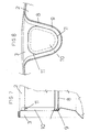
- Said basket is preferably made of a stainless steel material, or a chrome stainless steel material, AISI 430, and substantially comprises a perforated metal band 2, a front ring element 3, and a bottom member or disc 5 for closing the basket 1 and being applied at the rear side of the latter.
- the metal perforated band 2 in particular, forms the side cylindric wall 15 of the basket, whereas the front ring element 3 comprises a loading mouth 4 for front loading into the basket 1 the linen material to be washed and/or dried.
- the ring element would be replaced by an internally closed disc, i.e. a disc without loading mouth 4, whereas the band 2 would be provided with a door for introducing linen material to be washed.
- the bottom or disc element 5, provided for closing the basket construction 1 from its rear side, comprises a cross member 6 for supporting the drive shaft 7 for rotatively driving the basket construction.
- a plurality of entraining or driving wedge elements 8 are provided, made in a single-piece with said band.
- Said driving or entraining wedge elements are formed by a projection or lug and a deformed portion of the band 2, directed inward of the basket, and operating the latter to properly grip the linen material to be washed.
- each wedge element 8 facing the ring element 3, and provided for engaging therewith is prepared, before assembling, with an edge 9 formed by a wall facing the inside of the wedge element and being parallel to the surface of the front ring element 3, or substantially perpendicular to the axis of said wedge element.
- the edge 9 comprises material added by the front flange element or mouth.
- the surface of the ring element 3 comprises, at each wedge element 8, a window 10 substantially constituted by a hole having the configuration of the contour of the projecting edge 9 of the respective wedge element 8.
- edge portion or contour of the window 10 is so deformed as to provide an upturned or edge portion 11 facing the inside of the basket 1, i.e. a direction substantially perpendicular to the edge 9.
- connection of the ring element 3 on the band 2, at the level of the wedge elements 8 and windows 10, is better shown in figures 7 and 8, from which it should be apparent, in particular, that the ring element 3 is applied on the band 2, by engaging the edge portion 11 of the windows 10 inside the respective wedge element 8, by overlapping it, and arranging it cross-wise, with respect to the projecting edge 9 of the wedge element 8; thus, substantially providing a bridging arrangement.
- connection is made, in a centered manner, by abutting the edge portion 11 of the ring element 3 against the contour of the edge 9 of the wedge element 8, which is substantially arranged at 90°, with respect to the latter.
- the wedge portion 11, suitably guided by the bearing edge 9, is shown by a marked line in figure 8.
- This operation which is a cold operation, provides, in particular, that the edge portions 11 of the ring element 3 are at first inward or backward folded or bent and then pressed against the projecting edge 9 of the respective wedge element 8.
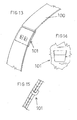
- At least a holding belt element 100 for strengthening or stiffening the assembly, so as to allow the basket to turn with a very high R.P.M. number is applied.
- the arrangement of the holding belt, with respect to the basket depth, can be changed, and will be determined by the thickness and height of the entraining or driving elements 8.
- Said belt will be pre-stretched depending on the test loads the basket will be subjected to.
- the joining point of the holding belt advantageously corresponds to the outer valley of the driving or entraining elements 8.
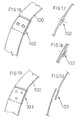
- Figures 13 to 15 show a joining performed by a clamping operation 101.
- This joining is advantageously carried out by performing a clamping operation at several points or spots.
- the joining can be carried out by clinching, as indicated by the reference number 102 in figures 16 to 18, or welding, as indicated by the reference number 103 in figures 19-10.
- the inventive method for making the improved basket 1, as above disclosed provides to prepare a cylindric band 2 including a plurality of wedge elements 8, having an edge 9 constituted by a wall inward projecting with respect to the wedge element and being substantially cross-oriented with respect to said wedge element, i.e. perpendicular to the surface of the above mentioned band 2.
- Said windows in particular, will be provided with an edge portion 11 perpendicular to the ring element 3 plane.
- the ring element 3 will be coupled on the cylindric band 2 by engaging the edge portions 11 inside the respective wedge elements 8, by arranging said edge portions in an overlapping relationship, substantially at 90° with respect to the related edge 9; thus the upsetting of each edge portion 11 against said edge 9, so as to be rearward bent and pressed against the surface of the latter, will provide a gripping action thereagainst; finally, one or more holding belts 100, as pre-stretched and joined by preferably a clamping, clinching, welding method or the like, will be applied.
- the wedge elements 8 can comprise an outward axially projecting portion 12, with respect to the band 2, thereby engaging within the windows 13 of the ring element or front cover 3.
- the mentioned windows are substantially analogous to the above disclosed windows, with a difference that they do not comprise projecting edge portions.
- connection is performed by upsetting the edge 12 of the wedge elements 8 inside the windows 13, by causing said edge 12 tc be rearward bent and then pressing it against the corresponding portion of the front ring element or cover 3.
- the projecting wall 9 provided to mutually engage the wedge element 8 and ring element 3 can be replaced by a simple ridge bead, to be engaged or gripped by the above disclosed upset portion of the edge part 11 of said ring element 3.
- said edge part 11 can be also formed in an independent manner from said windows 10.
- said windows 10 will provide an essential operating function only with reference to the modified embodiment shown in figures 10 and 11.
- the shape of the wedge elements 8 and the windows on the front ring element or cover can be any, depending on the specific designing requirements of the machine.
- the basket according to the present invention provides the advantage of a mechanical direct connection of the wedge elements and ring element or front cover, i.e. without any welding spots susceptible to alter the response of the material to oxidation phenomena, and its sealing properties with respect to the made connection.
- the mentioned mechanical sealing will be much more stable and efficient than conventional welded spot connections, since said mechanical sealing will extend to all the mutual attachment sections of the wedge elements and corresponding ring or front cover portion, and not only to a portion thereof, as it would occur in a conventional welding operation.
- the cold anchoring connection made by upsetting a projecting portion of the front ring or cover on the contour of the corresponding wedge element, provides the advantage of a "self-centering effect".
- the assembly cab be carried out in a very accurate automatic manner, owing to the mutual engagement of the parts involved in the connection, thereby providing a very accurate basket, finished to a very high finishing degree.
Landscapes
- Engineering & Computer Science (AREA)
- Textile Engineering (AREA)
- Main Body Construction Of Washing Machines And Laundry Dryers (AREA)
- Centrifugal Separators (AREA)
- Accessory Of Washing/Drying Machine, Commercial Washing/Drying Machine, Other Washing/Drying Machine (AREA)
- Detail Structures Of Washing Machines And Dryers (AREA)
- Cleaning By Liquid Or Steam (AREA)
Abstract
Description
Claims (15)
- A basket construction for washing, drying machines and the like, of the type comprising a cylindric band having a plurality of wedge elements facing an inside of the basket, a rear closure disc and a front ring element, characterized in that said basket construction further comprises coupling means for providing a mechanical direct connection of the ring element and band, at the wedge elements of said band, and at least a holding belt for said band.
- A basket construction, according to claim 1, characterized in that said at least a holding belt comprises a joining region arranged at an outer portion of a basket driving element.
- A basket construction, according to claim 1 or 2, characterized in that said belt joining region is made by a clamping operation.
- A basket construction, according to one or more of the preceding claims, characterized in that said belt joining region is made by a clamping operation at a plurality of clamping points.
- A basket construction, according to one or more of the preceding claims, characterized in that said joining of said belt is carried out by a clinching operation.
- A basket construction, according to one or more of the preceding claims, characterized in that said joining of said belt is carried out by a welding operation.
- A basket construction, according to one or more of the preceding claims, characterized in that said basket construction comprises two or more holding or restraining belts.
- A basket construction, according to one or more of the preceding claims, characterized in that said coupling means comprise projecting portions formed on an engagement section of each said wedge element with said ring element, said projecting portions cooperating with corresponding projecting portions of said ring element.
- A basket construction, according to one or more of the preceding claims, characterized in that said ring element projecting portions comprise a wall formed on an end portion of said wedge elements facing said ring element and oriented toward an inside of said wedge elements and at a position substantially parallel to the surface of said ring element thereon said wall is designed to be clamped.
- A basket construction, according to one or more of the preceding claims, characterized in that said ring element projecting portions comprise an edge portion formed at an attachment section on each said wedge element and having a shape and size adapted to be engaged inside each said wedge element, above and beyond said projecting wall.
- A basket construction, according to claim 10, characterized in that said edge portion comprises a wall oriented toward the inside of the basket.
- A basket construction, according to claim 10, characterized in that said edge portion, upon performing the mechanical connection, is rearward turned and clamped against the wall of the respective wedge element.
- A basket construction, according to claim 10, characterized in that said edge portion is formed by the sheared and upturned edge of a window arrangement formed on a surface portion of said ring element arranged at the level of each said wedge elements.
- A basket construction, according to one or more of the preceding claims, characterized in that said coupling means comprise a portion of said wedge elements axially projecting outside said cylindric band, designed for cooperating with a corresponding window arrangement of the front ring element, so as to be locked inside the latter, at its contour.
- A basket construction, according to one or more of the preceding claims, characterized in that, in replacement of said front ring element, a closed cover is provided, and that a mouth for laterally introducing into said basket linen material to be washed is formed on said cylindric band.
Applications Claiming Priority (2)
| Application Number | Priority Date | Filing Date | Title |
|---|---|---|---|
| ITMI20031631 | 2003-08-07 | ||
| IT001631A ITMI20031631A1 (en) | 2003-08-07 | 2003-08-07 | BASKET STRUCTURE FOR WASHING MACHINES, DRYERS AND THE LIKE. |
Publications (3)
| Publication Number | Publication Date |
|---|---|
| EP1505188A2 true EP1505188A2 (en) | 2005-02-09 |
| EP1505188A3 EP1505188A3 (en) | 2006-01-25 |
| EP1505188B1 EP1505188B1 (en) | 2009-04-08 |
Family
ID=33548868
Family Applications (1)
| Application Number | Title | Priority Date | Filing Date |
|---|---|---|---|
| EP04017184A Expired - Lifetime EP1505188B1 (en) | 2003-08-07 | 2004-07-21 | Washing machine basket construction |
Country Status (4)
| Country | Link |
|---|---|
| EP (1) | EP1505188B1 (en) |
| AT (1) | ATE428014T1 (en) |
| DE (1) | DE602004020430D1 (en) |
| IT (1) | ITMI20031631A1 (en) |
Cited By (11)
| Publication number | Priority date | Publication date | Assignee | Title |
|---|---|---|---|---|
| WO2006094902A1 (en) * | 2005-03-08 | 2006-09-14 | BSH Bosch und Siemens Hausgeräte GmbH | Drum for laundry washing machines |
| DE102005023444A1 (en) * | 2005-05-20 | 2006-11-23 | BSH Bosch und Siemens Hausgeräte GmbH | Drum with embossed seam |
| WO2007093466A1 (en) * | 2006-02-15 | 2007-08-23 | BSH Bosch und Siemens Hausgeräte GmbH | Washing machine laundry drum |
| WO2008122567A1 (en) * | 2007-04-04 | 2008-10-16 | BSH Bosch und Siemens Hausgeräte GmbH | Drum of a machine for the careful treatment of clothes |
| WO2009030638A1 (en) * | 2007-09-03 | 2009-03-12 | Arcelik Anonim Sirketi | A washer/dryer |
| EP1568812A3 (en) * | 2004-02-06 | 2010-08-11 | BSH Bosch und Siemens Hausgeräte GmbH | Reinforcing for a washing machine drum |
| CN101687287B (en) * | 2007-05-31 | 2011-08-03 | 空中客车控股有限公司 | Method for manufacturing composite skins in the field of aeronautics and aerospace |
| WO2011134736A1 (en) * | 2010-04-28 | 2011-11-03 | BSH Bosch und Siemens Hausgeräte GmbH | Drum of laundry care device |
| WO2016083073A1 (en) * | 2014-11-26 | 2016-06-02 | BSH Hausgeräte GmbH | Method for producing a folded connection in a domestic appliance component, and domestic appliance component |
| WO2020019935A1 (en) * | 2018-07-27 | 2020-01-30 | 青岛海尔滚筒洗衣机有限公司 | Drum hoop, drum and washing machine |
| WO2020076165A1 (en) * | 2018-10-12 | 2020-04-16 | Fisher & Paykel Appliances Limited | Laundry washing machine drum containment |
Families Citing this family (1)
| Publication number | Priority date | Publication date | Assignee | Title |
|---|---|---|---|---|
| US10676852B2 (en) | 2017-10-31 | 2020-06-09 | Haier Us Appliance Solutions, Inc. | Tub for a washing machine appliance |
Family Cites Families (7)
| Publication number | Priority date | Publication date | Assignee | Title |
|---|---|---|---|---|
| US1897615A (en) * | 1932-03-19 | 1933-02-14 | Robert L Logan | Cylinder for washing machines |
| GB853824A (en) * | 1957-11-22 | 1960-11-09 | Laden S A | Improvements in or relating to rotatable drums |
| FR1222378A (en) * | 1959-04-25 | 1960-06-09 | Centrifuge drum, in particular for washing machine and machine fitted with this drum | |
| FR2314963A1 (en) * | 1975-06-17 | 1977-01-14 | Thomson Brandt | DRUM LAUNDRY WASHING MACHINE, MANUFACTURING PROCESS AND DEVICES FOR IMPLEMENTING THIS PROCESS |
| IT1291667B1 (en) * | 1997-04-24 | 1999-01-19 | Miramondi Srl | PERFECTED BASKET FOR WASHING MACHINES, DRYERS AND SIMILAR AND PROCEDURE FOR ITS REALIZATION |
| DE19831274C1 (en) * | 1998-07-13 | 1999-09-30 | Whirlpool Co | Washing machine drum with laundry catches that are formed in one piece into the drum surface |
| DE10006975B4 (en) * | 2000-02-16 | 2004-08-12 | BSH Bosch und Siemens Hausgeräte GmbH | Washing drum for a washing machine |
-
2003
- 2003-08-07 IT IT001631A patent/ITMI20031631A1/en unknown
-
2004
- 2004-07-21 DE DE602004020430T patent/DE602004020430D1/en not_active Expired - Fee Related
- 2004-07-21 AT AT04017184T patent/ATE428014T1/en not_active IP Right Cessation
- 2004-07-21 EP EP04017184A patent/EP1505188B1/en not_active Expired - Lifetime
Cited By (24)
| Publication number | Priority date | Publication date | Assignee | Title |
|---|---|---|---|---|
| EP1568812A3 (en) * | 2004-02-06 | 2010-08-11 | BSH Bosch und Siemens Hausgeräte GmbH | Reinforcing for a washing machine drum |
| US7762109B2 (en) | 2005-03-08 | 2010-07-27 | Bsh Bosch Und Siemens Hausgeraete Gmbh | Drum for laundry washing machines |
| ES2284308A1 (en) * | 2005-03-08 | 2007-11-01 | Bsh Electrodomesticos España, S.A. | Drum for laundry washing machines |
| ES2284308B1 (en) * | 2005-03-08 | 2008-08-01 | Bsh Electrodomesticos España, S.A. | DRUM FOR CLOTHING WASHING MACHINE. |
| WO2006094902A1 (en) * | 2005-03-08 | 2006-09-14 | BSH Bosch und Siemens Hausgeräte GmbH | Drum for laundry washing machines |
| US8011210B2 (en) | 2005-05-20 | 2011-09-06 | Bsh Bosch Und Siemens Hausgeraete Gmbh | Washing drum for a laundry treating machine |
| DE102005023444A1 (en) * | 2005-05-20 | 2006-11-23 | BSH Bosch und Siemens Hausgeräte GmbH | Drum with embossed seam |
| CN101384765B (en) * | 2006-02-15 | 2011-03-30 | Bsh博世和西门子家用器具有限公司 | Washing machine laundry drum |
| WO2007093466A1 (en) * | 2006-02-15 | 2007-08-23 | BSH Bosch und Siemens Hausgeräte GmbH | Washing machine laundry drum |
| DE202007019494U1 (en) | 2006-02-15 | 2012-12-11 | BSH Bosch und Siemens Hausgeräte GmbH | Washing laundry drum |
| US8806904B2 (en) | 2006-02-15 | 2014-08-19 | Bsh Bosch Und Siemens Hausgeraete Gmbh | Washing machine laundry drum |
| WO2008122567A1 (en) * | 2007-04-04 | 2008-10-16 | BSH Bosch und Siemens Hausgeräte GmbH | Drum of a machine for the careful treatment of clothes |
| EA016057B1 (en) * | 2007-04-04 | 2012-01-30 | Бсх Бош Унд Сименс Хаусгерете Гмбх | Drum of a machine for the careful treatment of clothes |
| ES2306605B1 (en) * | 2007-04-04 | 2009-06-17 | Bsh Electrodomesticos España, S.A. | DRUM OF A CARE TREATY MACHINE OF CLOTHING. |
| ES2306605A1 (en) * | 2007-04-04 | 2008-11-01 | Bsh Electrodomesticos España, S.A. | Drum of a machine for the careful treatment of clothes |
| CN101687287B (en) * | 2007-05-31 | 2011-08-03 | 空中客车控股有限公司 | Method for manufacturing composite skins in the field of aeronautics and aerospace |
| US9314875B2 (en) | 2007-05-31 | 2016-04-19 | Airbus Operations Gmbh | Method for producing a composite skin in the field of aeronautics and astronautics |
| WO2009030638A1 (en) * | 2007-09-03 | 2009-03-12 | Arcelik Anonim Sirketi | A washer/dryer |
| WO2011134736A1 (en) * | 2010-04-28 | 2011-11-03 | BSH Bosch und Siemens Hausgeräte GmbH | Drum of laundry care device |
| WO2016083073A1 (en) * | 2014-11-26 | 2016-06-02 | BSH Hausgeräte GmbH | Method for producing a folded connection in a domestic appliance component, and domestic appliance component |
| CN107075770A (en) * | 2014-11-26 | 2017-08-18 | Bsh家用电器有限公司 | The method and home appliances component of connection are folded for being set up in family expenses furniture construction |
| CN107075770B (en) * | 2014-11-26 | 2019-08-30 | Bsh家用电器有限公司 | Method for producing a folded connection in a domestic appliance component and a domestic appliance component |
| WO2020019935A1 (en) * | 2018-07-27 | 2020-01-30 | 青岛海尔滚筒洗衣机有限公司 | Drum hoop, drum and washing machine |
| WO2020076165A1 (en) * | 2018-10-12 | 2020-04-16 | Fisher & Paykel Appliances Limited | Laundry washing machine drum containment |
Also Published As
| Publication number | Publication date |
|---|---|
| DE602004020430D1 (en) | 2009-05-20 |
| EP1505188B1 (en) | 2009-04-08 |
| ATE428014T1 (en) | 2009-04-15 |
| ITMI20031631A1 (en) | 2005-02-08 |
| EP1505188A3 (en) | 2006-01-25 |
Similar Documents
| Publication | Publication Date | Title |
|---|---|---|
| US6401363B1 (en) | Drum assembly for washing and drying machines and method for making it | |
| EP1505188B1 (en) | Washing machine basket construction | |
| EP1498536A2 (en) | Drum-type washing machine | |
| US20200032574A1 (en) | Welded steel door | |
| US5473798A (en) | Hose clip | |
| US20050028568A1 (en) | Externally supported lye tank | |
| JPH1045037A (en) | Panel reinforcement structure | |
| RU2394955C2 (en) | Linen drum for washing machine | |
| US2346619A (en) | Sheet metal container | |
| JPH0791723A (en) | Structure of air duct joints | |
| EP1550761B1 (en) | Washing machine | |
| EP1704274A1 (en) | A drum with stiffening corrugations along the seam | |
| AU635450B2 (en) | Casing of washing machine | |
| US20050005667A1 (en) | Cold-forged hitch receiver and method of making the same | |
| CA1165683A (en) | Attaching cover to sole-plate of steam iron | |
| JPH115125A (en) | Hydraulic bulge forming method | |
| JP2005349462A (en) | Panel joining structure and panel joining method | |
| KR200203345Y1 (en) | Hanger roller | |
| JPH05212468A (en) | Method and structure for joining with caulking | |
| JPH09250602A (en) | Transmission chain having welded joint pin and its manufacture | |
| EP3562982B1 (en) | A drum and its production method | |
| KR20050068527A (en) | Structure of reinforcement for base in clothes dryer | |
| KR100698255B1 (en) | Cabinet structure of drum type drying equipment | |
| KR100651984B1 (en) | Cabinet structure of drum type washing / drying device | |
| CA2047397A1 (en) | Simplified hinge apparatus and associated joining methods |
Legal Events
| Date | Code | Title | Description |
|---|---|---|---|
| PUAI | Public reference made under article 153(3) epc to a published international application that has entered the european phase |
Free format text: ORIGINAL CODE: 0009012 |
|
| AK | Designated contracting states |
Kind code of ref document: A2 Designated state(s): AT BE BG CH CY CZ DE DK EE ES FI FR GB GR HU IE IT LI LU MC NL PL PT RO SE SI SK TR |
|
| AX | Request for extension of the european patent |
Extension state: AL HR LT LV MK |
|
| PUAL | Search report despatched |
Free format text: ORIGINAL CODE: 0009013 |
|
| AK | Designated contracting states |
Kind code of ref document: A3 Designated state(s): AT BE BG CH CY CZ DE DK EE ES FI FR GB GR HU IE IT LI LU MC NL PL PT RO SE SI SK TR |
|
| AX | Request for extension of the european patent |
Extension state: AL HR LT LV MK |
|
| 17P | Request for examination filed |
Effective date: 20060420 |
|
| AKX | Designation fees paid |
Designated state(s): AT BE BG CH CY CZ DE DK EE ES FI FR GB GR HU IE IT LI LU MC NL PL PT RO SE SI SK TR |
|
| 17Q | First examination report despatched |
Effective date: 20080213 |
|
| GRAP | Despatch of communication of intention to grant a patent |
Free format text: ORIGINAL CODE: EPIDOSNIGR1 |
|
| GRAS | Grant fee paid |
Free format text: ORIGINAL CODE: EPIDOSNIGR3 |
|
| GRAA | (expected) grant |
Free format text: ORIGINAL CODE: 0009210 |
|
| AK | Designated contracting states |
Kind code of ref document: B1 Designated state(s): AT BE BG CH CY CZ DE DK EE ES FI FR GB GR HU IE IT LI LU MC NL PL PT RO SE SI SK TR |
|
| REG | Reference to a national code |
Ref country code: GB Ref legal event code: FG4D |
|
| REG | Reference to a national code |
Ref country code: CH Ref legal event code: EP |
|
| REG | Reference to a national code |
Ref country code: IE Ref legal event code: FG4D |
|
| REF | Corresponds to: |
Ref document number: 602004020430 Country of ref document: DE Date of ref document: 20090520 Kind code of ref document: P |
|
| PG25 | Lapsed in a contracting state [announced via postgrant information from national office to epo] |
Ref country code: SI Free format text: LAPSE BECAUSE OF FAILURE TO SUBMIT A TRANSLATION OF THE DESCRIPTION OR TO PAY THE FEE WITHIN THE PRESCRIBED TIME-LIMIT Effective date: 20090408 |
|
| NLV1 | Nl: lapsed or annulled due to failure to fulfill the requirements of art. 29p and 29m of the patents act | ||
| PG25 | Lapsed in a contracting state [announced via postgrant information from national office to epo] |
Ref country code: ES Free format text: LAPSE BECAUSE OF FAILURE TO SUBMIT A TRANSLATION OF THE DESCRIPTION OR TO PAY THE FEE WITHIN THE PRESCRIBED TIME-LIMIT Effective date: 20090719 Ref country code: FI Free format text: LAPSE BECAUSE OF FAILURE TO SUBMIT A TRANSLATION OF THE DESCRIPTION OR TO PAY THE FEE WITHIN THE PRESCRIBED TIME-LIMIT Effective date: 20090408 Ref country code: PT Free format text: LAPSE BECAUSE OF FAILURE TO SUBMIT A TRANSLATION OF THE DESCRIPTION OR TO PAY THE FEE WITHIN THE PRESCRIBED TIME-LIMIT Effective date: 20090908 Ref country code: AT Free format text: LAPSE BECAUSE OF FAILURE TO SUBMIT A TRANSLATION OF THE DESCRIPTION OR TO PAY THE FEE WITHIN THE PRESCRIBED TIME-LIMIT Effective date: 20090408 |
|
| PG25 | Lapsed in a contracting state [announced via postgrant information from national office to epo] |
Ref country code: NL Free format text: LAPSE BECAUSE OF FAILURE TO SUBMIT A TRANSLATION OF THE DESCRIPTION OR TO PAY THE FEE WITHIN THE PRESCRIBED TIME-LIMIT Effective date: 20090408 Ref country code: SE Free format text: LAPSE BECAUSE OF FAILURE TO SUBMIT A TRANSLATION OF THE DESCRIPTION OR TO PAY THE FEE WITHIN THE PRESCRIBED TIME-LIMIT Effective date: 20090708 Ref country code: PL Free format text: LAPSE BECAUSE OF FAILURE TO SUBMIT A TRANSLATION OF THE DESCRIPTION OR TO PAY THE FEE WITHIN THE PRESCRIBED TIME-LIMIT Effective date: 20090408 |
|
| PG25 | Lapsed in a contracting state [announced via postgrant information from national office to epo] |
Ref country code: EE Free format text: LAPSE BECAUSE OF FAILURE TO SUBMIT A TRANSLATION OF THE DESCRIPTION OR TO PAY THE FEE WITHIN THE PRESCRIBED TIME-LIMIT Effective date: 20090408 Ref country code: RO Free format text: LAPSE BECAUSE OF FAILURE TO SUBMIT A TRANSLATION OF THE DESCRIPTION OR TO PAY THE FEE WITHIN THE PRESCRIBED TIME-LIMIT Effective date: 20090408 Ref country code: DK Free format text: LAPSE BECAUSE OF FAILURE TO SUBMIT A TRANSLATION OF THE DESCRIPTION OR TO PAY THE FEE WITHIN THE PRESCRIBED TIME-LIMIT Effective date: 20090408 Ref country code: CZ Free format text: LAPSE BECAUSE OF FAILURE TO SUBMIT A TRANSLATION OF THE DESCRIPTION OR TO PAY THE FEE WITHIN THE PRESCRIBED TIME-LIMIT Effective date: 20090408 |
|
| PLBE | No opposition filed within time limit |
Free format text: ORIGINAL CODE: 0009261 |
|
| STAA | Information on the status of an ep patent application or granted ep patent |
Free format text: STATUS: NO OPPOSITION FILED WITHIN TIME LIMIT |
|
| PG25 | Lapsed in a contracting state [announced via postgrant information from national office to epo] |
Ref country code: SK Free format text: LAPSE BECAUSE OF FAILURE TO SUBMIT A TRANSLATION OF THE DESCRIPTION OR TO PAY THE FEE WITHIN THE PRESCRIBED TIME-LIMIT Effective date: 20090408 Ref country code: BE Free format text: LAPSE BECAUSE OF FAILURE TO SUBMIT A TRANSLATION OF THE DESCRIPTION OR TO PAY THE FEE WITHIN THE PRESCRIBED TIME-LIMIT Effective date: 20090408 Ref country code: MC Free format text: LAPSE BECAUSE OF NON-PAYMENT OF DUE FEES Effective date: 20090731 |
|
| REG | Reference to a national code |
Ref country code: CH Ref legal event code: PL |
|
| 26N | No opposition filed |
Effective date: 20100111 |
|
| GBPC | Gb: european patent ceased through non-payment of renewal fee |
Effective date: 20090721 |
|
| PG25 | Lapsed in a contracting state [announced via postgrant information from national office to epo] |
Ref country code: BG Free format text: LAPSE BECAUSE OF FAILURE TO SUBMIT A TRANSLATION OF THE DESCRIPTION OR TO PAY THE FEE WITHIN THE PRESCRIBED TIME-LIMIT Effective date: 20090708 |
|
| REG | Reference to a national code |
Ref country code: FR Ref legal event code: ST Effective date: 20100331 |
|
| REG | Reference to a national code |
Ref country code: IE Ref legal event code: MM4A |
|
| PG25 | Lapsed in a contracting state [announced via postgrant information from national office to epo] |
Ref country code: FR Free format text: LAPSE BECAUSE OF NON-PAYMENT OF DUE FEES Effective date: 20090731 Ref country code: LI Free format text: LAPSE BECAUSE OF NON-PAYMENT OF DUE FEES Effective date: 20090731 Ref country code: CH Free format text: LAPSE BECAUSE OF NON-PAYMENT OF DUE FEES Effective date: 20090731 |
|
| PG25 | Lapsed in a contracting state [announced via postgrant information from national office to epo] |
Ref country code: GB Free format text: LAPSE BECAUSE OF NON-PAYMENT OF DUE FEES Effective date: 20090721 |
|
| PG25 | Lapsed in a contracting state [announced via postgrant information from national office to epo] |
Ref country code: DE Free format text: LAPSE BECAUSE OF NON-PAYMENT OF DUE FEES Effective date: 20100202 |
|
| PG25 | Lapsed in a contracting state [announced via postgrant information from national office to epo] |
Ref country code: IE Free format text: LAPSE BECAUSE OF NON-PAYMENT OF DUE FEES Effective date: 20090721 |
|
| PG25 | Lapsed in a contracting state [announced via postgrant information from national office to epo] |
Ref country code: GR Free format text: LAPSE BECAUSE OF FAILURE TO SUBMIT A TRANSLATION OF THE DESCRIPTION OR TO PAY THE FEE WITHIN THE PRESCRIBED TIME-LIMIT Effective date: 20090709 |
|
| PG25 | Lapsed in a contracting state [announced via postgrant information from national office to epo] |
Ref country code: IT Free format text: LAPSE BECAUSE OF FAILURE TO SUBMIT A TRANSLATION OF THE DESCRIPTION OR TO PAY THE FEE WITHIN THE PRESCRIBED TIME-LIMIT Effective date: 20090408 |
|
| PG25 | Lapsed in a contracting state [announced via postgrant information from national office to epo] |
Ref country code: LU Free format text: LAPSE BECAUSE OF NON-PAYMENT OF DUE FEES Effective date: 20090721 |
|
| PG25 | Lapsed in a contracting state [announced via postgrant information from national office to epo] |
Ref country code: HU Free format text: LAPSE BECAUSE OF FAILURE TO SUBMIT A TRANSLATION OF THE DESCRIPTION OR TO PAY THE FEE WITHIN THE PRESCRIBED TIME-LIMIT Effective date: 20091009 |
|
| PG25 | Lapsed in a contracting state [announced via postgrant information from national office to epo] |
Ref country code: TR Free format text: LAPSE BECAUSE OF FAILURE TO SUBMIT A TRANSLATION OF THE DESCRIPTION OR TO PAY THE FEE WITHIN THE PRESCRIBED TIME-LIMIT Effective date: 20090408 |
|
| PG25 | Lapsed in a contracting state [announced via postgrant information from national office to epo] |
Ref country code: CY Free format text: LAPSE BECAUSE OF FAILURE TO SUBMIT A TRANSLATION OF THE DESCRIPTION OR TO PAY THE FEE WITHIN THE PRESCRIBED TIME-LIMIT Effective date: 20090408 |