EP1505261A1 - Dispositif de contrôle de jeu dans une turbine a gaz - Google Patents
Dispositif de contrôle de jeu dans une turbine a gaz Download PDFInfo
- Publication number
- EP1505261A1 EP1505261A1 EP04291818A EP04291818A EP1505261A1 EP 1505261 A1 EP1505261 A1 EP 1505261A1 EP 04291818 A EP04291818 A EP 04291818A EP 04291818 A EP04291818 A EP 04291818A EP 1505261 A1 EP1505261 A1 EP 1505261A1
- Authority
- EP
- European Patent Office
- Prior art keywords
- air
- ramps
- ring assembly
- air circulation
- spacers
- Prior art date
- Legal status (The legal status is an assumption and is not a legal conclusion. Google has not performed a legal analysis and makes no representation as to the accuracy of the status listed.)
- Granted
Links
- 125000006850 spacer group Chemical group 0.000 claims abstract description 37
- 238000011144 upstream manufacturing Methods 0.000 claims description 19
- 238000007789 sealing Methods 0.000 claims description 3
- 239000007789 gas Substances 0.000 description 13
- 230000008602 contraction Effects 0.000 description 3
- 238000005553 drilling Methods 0.000 description 3
- 238000002485 combustion reaction Methods 0.000 description 2
- 230000007423 decrease Effects 0.000 description 2
- 230000010339 dilation Effects 0.000 description 2
- 238000007599 discharging Methods 0.000 description 2
- 230000033228 biological regulation Effects 0.000 description 1
- 230000001627 detrimental effect Effects 0.000 description 1
- 230000000694 effects Effects 0.000 description 1
- 230000001105 regulatory effect Effects 0.000 description 1
- 238000005070 sampling Methods 0.000 description 1
- 210000003462 vein Anatomy 0.000 description 1
Images
Classifications
-
- F—MECHANICAL ENGINEERING; LIGHTING; HEATING; WEAPONS; BLASTING
- F01—MACHINES OR ENGINES IN GENERAL; ENGINE PLANTS IN GENERAL; STEAM ENGINES
- F01D—NON-POSITIVE DISPLACEMENT MACHINES OR ENGINES, e.g. STEAM TURBINES
- F01D11/00—Preventing or minimising internal leakage of working-fluid, e.g. between stages
- F01D11/08—Preventing or minimising internal leakage of working-fluid, e.g. between stages for sealing space between rotor blade tips and stator
- F01D11/14—Adjusting or regulating tip-clearance, i.e. distance between rotor-blade tips and stator casing
- F01D11/20—Actively adjusting tip-clearance
- F01D11/24—Actively adjusting tip-clearance by selectively cooling-heating stator or rotor components
Definitions
- the present invention relates to the general field of game control between the top of rotating blades and a set to fixed ring of a gas turbine.
- a gas turbine for example a high-pressure turbine of turbomachine, typically comprises a plurality of stationary vanes arranged alternating with a plurality of blades in the gas passage hot from the combustion chamber of the turbomachine.
- the blades movable turbine are surrounded on the entire circumference of the turbine by a set with fixed ring. This fixed ring set defines the flow of hot gases through the vanes of the turbine.
- Such means generally present in the form of annular conduits which surround the fixed ring assembly and are traversed by air taken from other parts of the turbomachine. This air is injected on the outer surface of the fixed ring assembly opposite the vein of hot gas flow and thus causes expansion or thermal contractions of the fixed ring assembly varying its diameter.
- these thermal dilations and contractions are controlled according to the operating speed of the gas turbine by through a valve that allows to control the flow and the temperature of the air supplying the pipes.
- the group consisting of pipes and the valve thus forms a game steering box at the top blade.
- the air of the steering boxes which was injected on the outer surface of the fixed ring assembly shall be evacuated to outside. This evacuation of the air must be able to take place without as much disturb the flow of air that is injected on the surface outer ring fixed assembly.
- the air to be evacuated generally tends to to disrupt the flow of air that is injected, which decreases the efficiency of the game steering box at the top of the blades.
- the present invention therefore aims to overcome such drawbacks by providing a game control device that allows you to obtain a high temperature homogeneity of the fixed ring assembly while avoiding disturbances between the air to be evacuated and the air to be injected.
- a game control device between the top of rotating vanes and a fixed ring assembly of a turbine to gas, the device comprising a circular control casing surrounding the fixed ring assembly, characterized in that the control box has at least two spaced apart annular air circulation ramps each other in the axial direction and each comprising a plurality of perforations to change the temperature of the fixed ring assembly by air discharge, an annular channel of spaced air supply radially of the air circulation ramps, at least one air duct for supplying air to the supply channel, and a plurality of spacers distribution channels connecting the air supply channel to the ramps circulation of air to supply air to the air while allowing the air having been discharged on the fixed ring assembly to flow between the supply canal and traffic ramps to be evacuated.
- Radial spacing between feed channel and ramps air flow control box provides a space for vent the air that has been discharged to the fixed ring assembly. In this way, the air that has been discharged is discharged radially and does not disturb the flow of air discharging on the fixed ring assembly.
- This radial spacing also makes it possible to avoid any exchange between the supply channel and the air circulation ramps of the control box, which improves the efficiency of the control device of play
- the fixed ring assembly comprises a housing internal which is surrounded by an outer casing of the gas turbine so to define an annular chamber in which is mounted the housing of piloting.
- the steering box may be in waterproof support, at a axial end upstream, against the outer casing, and at one axial end downstream, against the inner casing in order to define, inside the chamber ring, an upstream air discharge chamber and a downstream chamber exhaust air tight relative to the upstream enclosure.
- the arrangement, number and diameter of drilling Hollow distribution spacers regulate the airflow feeding the air circulation ramps and thus to homogenize the temperature of the fixed ring assembly.
- the distribution spacers connecting the channel feeding at one of the air circulation ramps can be angularly aligned or offset from the spacers of distribution of other air circulation ramps, and spacing angle between two successive distribution spacers does not exceed preferably no more than 45 °.
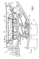
- FIG. 1 illustrates, in longitudinal section, a high-pressure turbine 2 turbomachine equipped with a game control device according to the invention.
- the present invention could also apply to a turbomachine low-pressure turbine or any other type of machine equipped with a game control device.
- the high-pressure turbine 2 is composed in particular of a plurality of blades 4 arranged in a flow passage of hot gases 6 from a combustion chamber (not shown) of the turbine engine. These blades 4 are arranged downstream of blades 8 of the turbine with respect to the flow direction of the hot gases in passage 6.
- the blades 4 of the high-pressure turbine 2 are surrounded by a plurality of fixed ring segments 14 arranged circumferentially around the axis of the turbine so as to form a circular and continuous surface.
- These ring segments 12 are mounted on an internal casing 14 of the turbomachine by means of a plurality 16.
- the inner casing 14 of the fixed ring assembly is provided with vanes or annular bumps 18 which have a disk shape extending in a radial direction.
- These fins 18 have the function principal to act as a heat exchanger. In Figure 1, the fins 18 There are two of them. However, we can imagine a number more important fins.
- the fixed ring segments 12 have an inner surface 12a directly in contact with the hot gases and which partly defines the flow passage of hot gases 6.
- a radial space is left between the inner surface 12a of the ring segments 12 and the top 4a of the turbine blades 4 of the turbine to allow rotation of the latter.
- This radial space thus defines a game 20 that it is necessary to reduce as much as possible so to increase the efficiency of the turbine.
- a game control device formed of a circular housing of steering 22 surrounding the fixed ring assembly, and more specifically the internal casing 14.
- this pilot box 22 is intended to cool or heat the fins 18 of the inner casing 14 by discharge (or impact) of air thereon. Under the effect of this discharge of air, the inner casing 14 retracts or expands, which decreases or increases the diameter of the fixed ring segments 12 of the turbine.
- control box 22 of the device game control comprises at least two annular traffic ramps air 24 spaced apart from each other in the axial direction. These ramps annular air circulation 24 surround the inner casing 14 of the fixed ring assembly.
- the air circulation ramps 24 each comprise a plurality of perforations 26 for discharging air on the fins 18 of the internal casing 14.
- perforations 26 of each ramp 24 are in the form of three rows of perforations.
- the fins 18 of the inner casing 14 are at number of two, so that the pilot box 22 has three air circulation ramps 24 spaced from each other in the axial direction: a central ramp 24a disposed between the two fins 18, and a ramp upstream 24b and a downstream ramp 24c disposed respectively upstream and downstream of the central ramp 24a.
- the air circulation ramps 24 marry approximately the shape of the fins 18. In this case, they present each a substantially rectangular cross section.
- the control box 22 also comprises an annular channel supplying air 28 to supply air to the traffic ramps
- the air supply channel 28 surrounds the ramps of circulation 24.
- At least one air line 30 opens into the feed channel 28 to supply it with air.
- the air circulating in the air duct 30 is taken from other levels parts of the turbomachine. For example, this air can be taken from level of one or more stages of high or low compressors pressure of the turbomachine, or at the blower thereof.
- the air sampling is controlled by a valve of regulation (not shown) which allows to provide air more or less charge to the pilot box 22 according to the operating regime of the turbine engine.
- the air supply channel 28 and the traffic ramps 24 are radially spaced and are interconnected by a plurality of hollow distribution spacers 32.
- the hollow distribution spacers 32 supply the air with traffic ramps 24 while allowing the air having been discharged on the fins 18 of the inner casing 14 to circulate axially between the channel supply air 28 and the air circulation ramps 24 to be there evacuated.
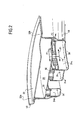
- Figure 2 illustrates more precisely the path of the air intended to be evacuated.
- the arrows F1 represent the Tangential directions of air flow in the feed channel 28 and in the air circulation ramps 24, while the F2 arrow illustrates the axial direction of flow of the air having been discharged on the fins of the inner casing.
- the turbine 2 is advantageously provided with an outer casing 34 surrounding the casing internal 14 of the fixed ring assembly. At an upstream axial end, this outer casing 34 is fixed to the inner casing 14 by a fastener 36 of the type screw nut.
- the internal casings 14 and outer 34 define between them a annular chamber 38 in which is mounted the control box 22 of the game control device according to the invention. More precisely, the housing 22 is supported, at an upstream axial end 22a, against the outer casing 34, and, at a downstream axial end 22b, against the casing 14. Preferably, the support of the upstream ends 22a and downstream 22b of the control box 22 is effected in a sealed manner, via of seals 40.
- control box 22 with respect to internal casings 14 and outer 34 and allows to define, inside of the annular chamber 38, an upstream chamber 42a called “discharge of air "and a downstream enclosure 42b called” exhaust air “which is waterproof in the air relative to the upstream chamber 42a.
- the air that has been discharged by the air circulation ramps 24, and in particular by the upstream ramp 24b, is confined in the enclosure upstream discharge 42a and can be evacuated by circulating between the supply channel 28 and the traffic ramps 24.
- the sealing performed at the upstream end 22a of the control box 22 prevents air from bypassing the pilot housing 22 to be evacuated.
- the air that has been discharged by the downstream ramp 24c is constrained by the sealing performed at the downstream end 22b of the control box 22, circulate between the supply channel 28 and the traffic ramps 24 to be evacuated.
- the air that has been discharged on fins 18 of the inner casing 14 and which is evacuated between the channel supply 28 and the traffic ramps 24 is then confined in the downstream exhaust air chamber 42b.
- the inner casing 14 has, at one end axial downstream, an opening 44 opening in the downstream exhaust enclosure 42b air to evacuate the air confined therein.
- This opening 44 which can provided with a sleeve 46, thus evacuate the air having been discharged on the fins 18 of the inner casing to feed for example the first floor a low-pressure distributor (not shown) of the turbomachine.
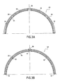
- FIGS. 3A and 3B We will now describe two possible configurations of game control device according to the invention by referring more particularly in FIGS. 3A and 3B.
- the steering box is composed of two distinct angular sectors housing 48 (or half-housings of 180 ° each) of which only one is shown in Figures 3A and 3B. These two casing sectors 48 are fixed together by fasteners of the type screw / nut which cooperate with orifices 50 (FIG. 1) arranged at each angular end of the housing sectors.
- pilot box is composed of more than two distinct angular sectors of housing which, once put end to end, together form a 360 ° housing.
- Housing sectors 48 shown in FIGS. 3A and 3B are closed at each of their angular ends, so that the air does not not move from one housing sector to another. However, it is also possible to make a connection between the housing sectors in order to allow a passage of air from one housing sector to another.
- Each housing sector 48 is also powered by a single air duct 30 opening into the feed channel 28 to equidistant from the two angular ends of the housing sector.
- the air duct could also lead to one of the angular ends housing sector.
- air ducts are also conceivable.
- each case sector 48 four hollow distribution spacers 32 connecting the feed channel 28 at the traffic ramp 24 shown.
- These hollow spacers of distribution 32 are arranged on the half-circumference of the sector of casing 48 so that the angular distance between two spacers successive does not exceed preferably 45 °.
- five hollow distribution spacers 32 connect the supply channel 28 to the circulation ramp 24 shown. More particularly, a distribution spacer is arranged at each angular end of the housing sector and the angular distance between two successive spacers preferably do not exceed preferably 45 ° about.
- Hollow distribution spacers may vary for each boom air circulation of the same housing sector.
- the hollow spacers distribution system connecting the feed channel to one of the air circulation can be angularly offset from hollow distribution spacers connecting the feed channel with least one of the other air circulation ramps.
- the angular offset of the hollow distribution spacers between the air circulation ramps allows for better homogeneity of temperature in the control box and to avoid any distortion of the fixed ring assembly.
- Such an angular offset can for example be obtained in the case of the same housing sector with three traffic ramps as in Figures 1 and 2.
- the central ramp 24a (or conversely the upstream ramps 24b and downstream 24c) can have the configuration of Figure 3A
- the upstream ramps 24b and downstream 24c (or conversely the central ramp 24a) can have the configuration of Figure 3B.
- Such a provision is similar for the three ramps 24a, 24b and 24c, in a quincunx arrangement of distribution spacers 32 with a symmetry of arrangement between the upstream ramp 24b and the downstream ramp 24c.
- This symmetry of arrangement makes it possible to obtain a dilation or a substantially identical thermal contraction between the two fins 18 of the internal casing 14 so as to improve the temperature homogeneity of the fixed ring assembly.
- the hollow distribution spacers connecting the supply channel of the same sector of housing to one of the ramps of air circulation can be aligned angularly with respect to hollow distribution spacers connecting the feed channel with the other air circulation ramps.
- an angular alignment of the hollow spacers of FIGS. distribution can be achieved by giving to the three traffic ramps of air the same configuration.
- this configuration of the three air circulation ramps may be identical to that of Figure 3A or Figure 3B.
- each air circulation of the same sector of housing is supplied with air than by a single hollow distribution spacer connected to the canal Power.
- this distribution spacer is an angular end of the housing sector, the circulation of air in the ramp is carried out only in one and the same tangential direction.
- the drilling diameter of the hollow distribution spacers may vary from one spacer to another for the same traffic ramp air.
- the variation of the diameter of the distribution spacers thus offers the possibility of regulating the air flow supplying the next ramp the angular location of the spacer so as to improve the temperature homogeneity of the fixed ring assembly.
- the number, the Drilling diameter and layout of the distribution spacers may vary for the same traffic ramp and for the same housing sector. These different parameters are chosen so as to minimize distortion of the fixed ring assembly.
Landscapes
- Engineering & Computer Science (AREA)
- Mechanical Engineering (AREA)
- General Engineering & Computer Science (AREA)
- Turbine Rotor Nozzle Sealing (AREA)
- Structures Of Non-Positive Displacement Pumps (AREA)
Abstract
Description
- la figure 1 est une vue en coupe longitudinale d'un dispositif de contrôle de jeu selon l'invention ;
- la figure 2 est une vue partielle en perspective et en écorché du dispositif de contrôle de jeu de la figure 1 ; et
- les figures 3A et 3B illustrent partiellement en coupe transversale deux configurations possibles du dispositif de contrôle de jeu selon l'invention.
Claims (9)
- Dispositif de contrôle de jeu entre le sommet (4a) d'aubes rotatives (4) et un ensemble à anneau fixe d'une turbine à gaz (2), ledit dispositif comprenant un boítier circulaire de pilotage (22) entourant ledit ensemble à anneau fixe,
caractérisé en ce que ledit boítier de pilotage (22) comporte :au moins deux rampes annulaires de circulation d'air (24a, 24b, 24c) espacées l'une de l'autre dans le sens axial et comportant chacune une pluralité de perforations (26) pour modifier la température de l'ensemble à anneau fixe par décharge d'air ;un canal annulaire d'alimentation en air (28) espacé radialement desdites rampes de circulation d'air (24a, 24b, 24c) ;au moins une conduite d'air (30) pour alimenter en air ledit canal d'alimentation (28) ; etune pluralité d'entretoises creuses de distribution (32) reliant ledit canal d'alimentation en air (28) auxdites rampes de circulation d'air (24a, 24b, 24c) afin d'alimenter en air ces dernières tout en permettant à l'air ayant été déchargé sur l'ensemble à anneau fixe de circuler entre ledit canal d'alimentation (28) et lesdites rampes de circulation (24a, 24b, 24c) pour y être évacué. - Dispositif selon la revendication 1, caractérisé en ce que l'ensemble à anneau fixe comporte un carter interne (14) qui est entouré par un carter externe (34) de la turbine à gaz (2) de façon à définir une chambre annulaire (38) dans laquelle est monté ledit boítier de pilotage (22).
- Dispositif selon la revendication 2, caractérisé en ce que ledit boítier de pilotage (28) est en appui étanche, à une extrémité axiale amont (22a), contre le carter externe (34), et, à une extrémité axiale aval (22b), contre le carter interne (14) afin de définir, à l'intérieur de ladite chambre annulaire (38), une enceinte amont de décharge d'air (42a) et une enceinte aval d'évacuation d'air (42b) étanche par rapport à ladite enceinte amont (42a).
- Dispositif selon la revendication 3, caractérisé en ce que ledit carter interne (14) présente, à une extrémité axiale aval, une ouverture d'air (44) s'ouvrant dans l'enceinte aval d'évacuation d'air (42b) afin d'évacuer l'air ayant été déchargé sur l'ensemble à anneau fixe.
- Dispositif selon l'une quelconque des revendications 2 à 4, caractérisé en ce que le carter interne (14) comprend des ailettes annulaires (18) et en ce que les rampes de circulation d'air (24a, 24b, 24c) épousent sensiblement la forme desdites ailettes (18).
- Dispositif selon l'une quelconque des revendications 1 à 5, caractérisé en ce que ledit boítier de pilotage (22) se compose d'au moins deux secteurs angulaires distincts de boítier (48).
- Dispositif selon l'une quelconque des revendications 1 à 6, caractérisé en ce que les entretoises creuses de distribution (32) reliant le canal d'alimentation (28) à l'une des rampes de circulation d'air (24a, 24b, 24c) sont décalées angulairement par rapport aux entretoises creuses de distribution (32) reliant ledit canal d'alimentation (28) avec au moins l'une des autres rampes de circulation d'air (24a, 24b, 24c).
- Dispositif selon l'une quelconque des revendications 1 à 6, caractérisé en ce que les entretoises creuses de distribution (32) reliant le canal d'alimentation (28) à l'une des rampes de circulation d'air (24a, 24b, 24c) sont alignées angulairement par rapport aux entretoises creuses de distribution (32) reliant ledit canal d'alimentation (28) avec les autres rampes de circulation d'air (24a, 24b, 24c).
- Dispositif selon l'une quelconque des revendications 1 à 8, caractérisé en ce que l'espacement angulaire entre deux entretoises creuses de distribution successives (32) ne dépasse pas 45° environ.
Applications Claiming Priority (2)
| Application Number | Priority Date | Filing Date | Title |
|---|---|---|---|
| FR0309686A FR2858652B1 (fr) | 2003-08-06 | 2003-08-06 | Dispositif de controle de jeu dans une turbine a gaz |
| FR0309686 | 2003-08-06 |
Publications (2)
| Publication Number | Publication Date |
|---|---|
| EP1505261A1 true EP1505261A1 (fr) | 2005-02-09 |
| EP1505261B1 EP1505261B1 (fr) | 2008-02-20 |
Family
ID=33548308
Family Applications (1)
| Application Number | Title | Priority Date | Filing Date |
|---|---|---|---|
| EP04291818A Expired - Lifetime EP1505261B1 (fr) | 2003-08-06 | 2004-07-16 | Dispositif de contrôle de jeu dans une turbine a gaz |
Country Status (9)
| Country | Link |
|---|---|
| US (1) | US7114914B2 (fr) |
| EP (1) | EP1505261B1 (fr) |
| JP (1) | JP4185476B2 (fr) |
| CA (1) | CA2475081C (fr) |
| DE (1) | DE602004011859T2 (fr) |
| ES (1) | ES2300722T3 (fr) |
| FR (1) | FR2858652B1 (fr) |
| RU (1) | RU2290515C2 (fr) |
| UA (1) | UA83188C2 (fr) |
Cited By (9)
| Publication number | Priority date | Publication date | Assignee | Title |
|---|---|---|---|---|
| WO2009144191A1 (fr) * | 2008-05-28 | 2009-12-03 | Snecma | Turbine haute pression d'une turbomachine avec montage ameliore du boitier de pilotage des jeux radiaux d'aubes mobiles |
| EP2243931A3 (fr) * | 2009-04-16 | 2013-09-18 | Rolls-Royce plc | Refroidissement de carter de turbine |
| GB2518946A (en) * | 2013-08-07 | 2015-04-08 | Snecma | Turbine casing made of two materials |
| EP2987966A1 (fr) * | 2014-08-21 | 2016-02-24 | Siemens Aktiengesellschaft | Turbine à gaz dotée de canal de refroidissement divisé en sections annulaires |
| EP2987965A1 (fr) * | 2014-08-21 | 2016-02-24 | Siemens Aktiengesellschaft | Turbine à gaz dotée d'un canal de ceinture comprenant un tube distributeur |
| EP3091195A1 (fr) * | 2015-05-08 | 2016-11-09 | General Electric Company | Système et procédé de commande de jeu actif alimenté en énergie par la chaleur perdue |
| EP2372105A3 (fr) * | 2010-03-17 | 2016-11-16 | Rolls-Royce plc | Réglage de jeu de l'extrémité d'une aube de rotor |
| WO2018229385A1 (fr) | 2017-06-15 | 2018-12-20 | Safran Aircraft Engines | Dispositif de refroidissement d'un carter annulaire externe de turbine |
| FR3114345A1 (fr) * | 2020-09-23 | 2022-03-25 | Safran Aircraft Engines | Dispositif de pilotage de jeux pour une turbine de turbomachine |
Families Citing this family (31)
| Publication number | Priority date | Publication date | Assignee | Title |
|---|---|---|---|---|
| US7310952B2 (en) * | 2003-10-17 | 2007-12-25 | General Electric Company | Methods and apparatus for attaching swirlers to gas turbine engine combustors |
| US7491029B2 (en) | 2005-10-14 | 2009-02-17 | United Technologies Corporation | Active clearance control system for gas turbine engines |
| FR2906846B1 (fr) * | 2006-10-06 | 2008-12-26 | Snecma Sa | Canal de transition entre deux etages de turbine |
| US7785063B2 (en) * | 2006-12-15 | 2010-08-31 | Siemens Energy, Inc. | Tip clearance control |
| US8123466B2 (en) * | 2007-03-01 | 2012-02-28 | United Technologies Corporation | Blade outer air seal |
| FR2922589B1 (fr) * | 2007-10-22 | 2009-12-04 | Snecma | Controle du jeu en sommet d'aubes dans une turbine haute-pression de turbomachine |
| FR2923525B1 (fr) * | 2007-11-13 | 2009-12-18 | Snecma | Etancheite d'un anneau de rotor dans un etage de turbine |
| FR2926327B1 (fr) * | 2008-01-11 | 2010-03-05 | Snecma | Moteur a turbine a gaz avec clapet de mise en communication de deux enceintes |
| GB2467910B (en) * | 2009-02-16 | 2011-12-14 | Rolls Royce Plc | Combination of mechanical actuator and case cooling apparatus |
| US8342798B2 (en) * | 2009-07-28 | 2013-01-01 | General Electric Company | System and method for clearance control in a rotary machine |
| GB201013723D0 (en) * | 2010-08-17 | 2010-09-29 | Rolls Royce Plc | Manifold mounting arrangement |
| JP2012072708A (ja) * | 2010-09-29 | 2012-04-12 | Hitachi Ltd | ガスタービンおよびガスタービンの冷却方法 |
| FR2965583B1 (fr) * | 2010-10-04 | 2012-09-14 | Snecma | Dispositif de pilotage de jeu dans une turbine de turbomachine |
| FR2972483B1 (fr) * | 2011-03-07 | 2013-04-19 | Snecma | Carter de turbine comportant des moyens de fixation de secteurs d'anneau |
| JP5478576B2 (ja) * | 2011-09-20 | 2014-04-23 | 株式会社日立製作所 | ガスタービン |
| RU2506434C2 (ru) * | 2012-04-04 | 2014-02-10 | Николай Борисович Болотин | Газотурбинный двигатель |
| RU2506433C2 (ru) * | 2012-04-04 | 2014-02-10 | Николай Борисович Болотин | Газотурбинный двигатель |
| RU2498085C1 (ru) * | 2012-04-04 | 2013-11-10 | Николай Борисович Болотин | Газотурбинный двигатель |
| US9322415B2 (en) * | 2012-10-29 | 2016-04-26 | United Technologies Corporation | Blast shield for high pressure compressor |
| JP6223111B2 (ja) * | 2013-10-15 | 2017-11-01 | 三菱日立パワーシステムズ株式会社 | ガスタービン |
| US9869196B2 (en) * | 2014-06-24 | 2018-01-16 | General Electric Company | Gas turbine engine spring mounted manifold |
| US10316696B2 (en) | 2015-05-08 | 2019-06-11 | General Electric Company | System and method for improving exhaust energy recovery |
| US10513944B2 (en) * | 2015-12-21 | 2019-12-24 | General Electric Company | Manifold for use in a clearance control system and method of manufacturing |
| US10612409B2 (en) * | 2016-08-18 | 2020-04-07 | United Technologies Corporation | Active clearance control collector to manifold insert |
| US10704560B2 (en) | 2018-06-13 | 2020-07-07 | Rolls-Royce Corporation | Passive clearance control for a centrifugal impeller shroud |
| FR3096071B1 (fr) | 2019-05-16 | 2022-08-26 | Safran Aircraft Engines | Contrôle de jeu entre des aubes de rotor d’aéronef et un carter |
| US11293298B2 (en) | 2019-12-05 | 2022-04-05 | Raytheon Technologies Corporation | Heat transfer coefficients in a compressor case for improved tip clearance control system |
| US11788425B2 (en) * | 2021-11-05 | 2023-10-17 | General Electric Company | Gas turbine engine with clearance control system |
| CN116085067A (zh) | 2021-11-05 | 2023-05-09 | 通用电气公司 | 具有流体导管系统的燃气涡轮发动机及其操作方法 |
| US12345163B2 (en) | 2023-11-17 | 2025-07-01 | Rolls-Royce Corporation | Travel stop for a tip clearance control system |
| US12345162B2 (en) | 2023-11-17 | 2025-07-01 | Rolls-Royce Corporation | Adjustable position impeller shroud for centrifugal compressors |
Citations (3)
| Publication number | Priority date | Publication date | Assignee | Title |
|---|---|---|---|---|
| DE3909369A1 (de) * | 1988-03-31 | 1989-10-26 | Gen Electric | Gasturbinen-spaltsteuerung |
| EP0541325A1 (fr) * | 1991-11-04 | 1993-05-12 | General Electric Company | Contrôle thermique du jeu d'extrémités d'aubes de turbines à gaz |
| US6035929A (en) * | 1997-07-18 | 2000-03-14 | Societe Nationale D'etude Et De Construction De Moteurs D'aviation "Snecma" | Apparatus for heating or cooling a circular housing |
Family Cites Families (5)
| Publication number | Priority date | Publication date | Assignee | Title |
|---|---|---|---|---|
| US4337016A (en) * | 1979-12-13 | 1982-06-29 | United Technologies Corporation | Dual wall seal means |
| US5281085A (en) * | 1990-12-21 | 1994-01-25 | General Electric Company | Clearance control system for separately expanding or contracting individual portions of an annular shroud |
| FR2780443B1 (fr) * | 1998-06-25 | 2000-08-04 | Snecma | Anneau de stator de turbine haute pression d'une turbomachine |
| RU2151886C1 (ru) * | 1998-08-04 | 2000-06-27 | Открытое акционерное общество "Авиадвигатель" | Статор многоступенчатой газовой турбины |
| US6309177B1 (en) * | 1999-06-08 | 2001-10-30 | Pratt & Whitney Canada Corp. | Concentricity ring |
-
2003
- 2003-08-06 FR FR0309686A patent/FR2858652B1/fr not_active Expired - Fee Related
-
2004
- 2004-07-16 ES ES04291818T patent/ES2300722T3/es not_active Expired - Lifetime
- 2004-07-16 DE DE602004011859T patent/DE602004011859T2/de not_active Expired - Lifetime
- 2004-07-16 EP EP04291818A patent/EP1505261B1/fr not_active Expired - Lifetime
- 2004-07-21 CA CA2475081A patent/CA2475081C/fr not_active Expired - Lifetime
- 2004-07-21 JP JP2004212950A patent/JP4185476B2/ja not_active Expired - Lifetime
- 2004-07-22 US US10/895,857 patent/US7114914B2/en not_active Expired - Lifetime
- 2004-07-26 RU RU2004122668/06A patent/RU2290515C2/ru active
- 2004-08-04 UA UA20040806525A patent/UA83188C2/uk unknown
Patent Citations (3)
| Publication number | Priority date | Publication date | Assignee | Title |
|---|---|---|---|---|
| DE3909369A1 (de) * | 1988-03-31 | 1989-10-26 | Gen Electric | Gasturbinen-spaltsteuerung |
| EP0541325A1 (fr) * | 1991-11-04 | 1993-05-12 | General Electric Company | Contrôle thermique du jeu d'extrémités d'aubes de turbines à gaz |
| US6035929A (en) * | 1997-07-18 | 2000-03-14 | Societe Nationale D'etude Et De Construction De Moteurs D'aviation "Snecma" | Apparatus for heating or cooling a circular housing |
Cited By (17)
| Publication number | Priority date | Publication date | Assignee | Title |
|---|---|---|---|---|
| WO2009144191A1 (fr) * | 2008-05-28 | 2009-12-03 | Snecma | Turbine haute pression d'une turbomachine avec montage ameliore du boitier de pilotage des jeux radiaux d'aubes mobiles |
| FR2931872A1 (fr) * | 2008-05-28 | 2009-12-04 | Snecma | Turbine haute pression d'une turbomachine avec montage ameliore du boitier de pilotage des jeux radiaux d'aubes mobiles. |
| US8662828B2 (en) | 2008-05-28 | 2014-03-04 | Snecma | High pressure turbine of a turbomachine with improved assembly of the mobile blade radial clearance control box |
| EP2243931A3 (fr) * | 2009-04-16 | 2013-09-18 | Rolls-Royce plc | Refroidissement de carter de turbine |
| US8668438B2 (en) | 2009-04-16 | 2014-03-11 | Rolls-Royce Plc | Turbine casing cooling |
| EP2372105A3 (fr) * | 2010-03-17 | 2016-11-16 | Rolls-Royce plc | Réglage de jeu de l'extrémité d'une aube de rotor |
| GB2518946A (en) * | 2013-08-07 | 2015-04-08 | Snecma | Turbine casing made of two materials |
| GB2518946B (en) * | 2013-08-07 | 2020-09-09 | Snecma | Turbine casing made of two materials |
| WO2016026752A1 (fr) * | 2014-08-21 | 2016-02-25 | Siemens Aktiengesellschaft | Turbine à gaz pourvue d'un conduit annulaire divisé en secteurs d'anneau |
| EP2987965A1 (fr) * | 2014-08-21 | 2016-02-24 | Siemens Aktiengesellschaft | Turbine à gaz dotée d'un canal de ceinture comprenant un tube distributeur |
| US10294818B2 (en) | 2014-08-21 | 2019-05-21 | Siemens Aktiengesellschaft | Gas turbine having an annular passage subdivided into annulus sectors |
| EP2987966A1 (fr) * | 2014-08-21 | 2016-02-24 | Siemens Aktiengesellschaft | Turbine à gaz dotée de canal de refroidissement divisé en sections annulaires |
| EP3091195A1 (fr) * | 2015-05-08 | 2016-11-09 | General Electric Company | Système et procédé de commande de jeu actif alimenté en énergie par la chaleur perdue |
| WO2018229385A1 (fr) | 2017-06-15 | 2018-12-20 | Safran Aircraft Engines | Dispositif de refroidissement d'un carter annulaire externe de turbine |
| FR3067751A1 (fr) * | 2017-06-15 | 2018-12-21 | Safran Aircraft Engines | Dispositif de refroidissement d'un carter annulaire externe de turbine |
| US11542833B2 (en) | 2017-06-15 | 2023-01-03 | Safran Aircraft Engines | Device for cooling an annular outer turbine casing |
| FR3114345A1 (fr) * | 2020-09-23 | 2022-03-25 | Safran Aircraft Engines | Dispositif de pilotage de jeux pour une turbine de turbomachine |
Also Published As
| Publication number | Publication date |
|---|---|
| DE602004011859D1 (de) | 2008-04-03 |
| JP2005054777A (ja) | 2005-03-03 |
| JP4185476B2 (ja) | 2008-11-26 |
| US7114914B2 (en) | 2006-10-03 |
| CA2475081C (fr) | 2011-09-13 |
| US20050042080A1 (en) | 2005-02-24 |
| UA83188C2 (uk) | 2008-06-25 |
| FR2858652A1 (fr) | 2005-02-11 |
| ES2300722T3 (es) | 2008-06-16 |
| CA2475081A1 (fr) | 2005-02-06 |
| EP1505261B1 (fr) | 2008-02-20 |
| RU2290515C2 (ru) | 2006-12-27 |
| RU2004122668A (ru) | 2006-01-27 |
| DE602004011859T2 (de) | 2009-02-12 |
| FR2858652B1 (fr) | 2006-02-10 |
Similar Documents
| Publication | Publication Date | Title |
|---|---|---|
| CA2475081C (fr) | Dispositif de controle de jeu dans une turbine a gaz | |
| CA2491666C (fr) | Perfectionnements apportes au dispositif de controle de jeu dans une turbine a gaz | |
| EP0176447B1 (fr) | Dispositif de contrôle automatique du jeu d'un joint à labyrinthe de turbomachine | |
| EP1526253B1 (fr) | Dispositif de joint à labyrinthe pour moteur à turbine à gaz | |
| EP1445421B1 (fr) | Dispositif de ventilation d'un rotor de turbine à haute pression d'une turbomachine | |
| EP1847687A1 (fr) | Dispositif de refroidissement d'un carter de turbine d'une turbomachine et distributeur associé | |
| FR2867806A1 (fr) | Dispositif de pilotage de jeu de turbine a gaz a equilibrage des debits d'air | |
| CA2827591C (fr) | Carter de turbine comportant des moyens de fixation de secteurs d'anneau | |
| FR2467292A1 (fr) | Dispositif de reglage du jeu entre les aubes mobiles et l'anneau de turbine | |
| EP3318725A1 (fr) | Ensemble de raccordement pour le refroidissement d'une turbine de turbomachine | |
| EP3519700B1 (fr) | Déflecteur de flux d'un système de vanne de décharge, système de vanne de décharge et turbomachine comprenant un tel système de vanne de décharge | |
| FR2534982A1 (fr) | Dispositif de controle des jeux d'un compresseur haute pression | |
| EP4127405B1 (fr) | Turbomachine avec dispositif de refroidissement et de pressurisation d'une turbine | |
| FR3021351A1 (fr) | Paroi de turbomachine comportant une partie au moins d'orifices de refroidissement obtures | |
| EP3535479B1 (fr) | Dispositif de refroidissement pour une turbine d'une turbomachine | |
| EP4136327B1 (fr) | Dispositif de refroidissement d'un carter de turbine | |
| FR3106609A1 (fr) | Dispositif amélioré de limitation de débit de fuite pour turbines d’aéronef | |
| FR3045717A1 (fr) | Dispositif de pilotage de jeu en sommets d'aubes rotatives de turbine | |
| CA2500493C (fr) | Stator de turbine haute-pression de turbomachine et procede d'assemblage | |
| CA3099889A1 (fr) | Dispositif de refroidissement d'un carter de turbomachine | |
| CA2997939A1 (fr) | Dispositif de ventilation d'un carter de turbine d'une turbomachine | |
| EP4409113B1 (fr) | Turbine à gaz haute-pression pour une turbomachine et turbomachine | |
| EP3999779B1 (fr) | Chambre de combustion de turbomachine a volume constant | |
| FR3061739A1 (fr) | Ensemble pour turbomachine | |
| WO2026052915A1 (fr) | Module pour une turbomachine d'aeronef |
Legal Events
| Date | Code | Title | Description |
|---|---|---|---|
| PUAI | Public reference made under article 153(3) epc to a published international application that has entered the european phase |
Free format text: ORIGINAL CODE: 0009012 |
|
| 17P | Request for examination filed |
Effective date: 20040730 |
|
| AK | Designated contracting states |
Kind code of ref document: A1 Designated state(s): AT BE BG CH CY CZ DE DK EE ES FI FR GB GR HU IE IT LI LU MC NL PL PT RO SE SI SK TR |
|
| AX | Request for extension of the european patent |
Extension state: AL HR LT LV MK |
|
| RAP1 | Party data changed (applicant data changed or rights of an application transferred) |
Owner name: SNECMA |
|
| AKX | Designation fees paid |
Designated state(s): DE ES FR GB IT SE |
|
| GRAP | Despatch of communication of intention to grant a patent |
Free format text: ORIGINAL CODE: EPIDOSNIGR1 |
|
| GRAS | Grant fee paid |
Free format text: ORIGINAL CODE: EPIDOSNIGR3 |
|
| GRAA | (expected) grant |
Free format text: ORIGINAL CODE: 0009210 |
|
| AK | Designated contracting states |
Kind code of ref document: B1 Designated state(s): DE ES FR GB IT SE |
|
| REG | Reference to a national code |
Ref country code: GB Ref legal event code: FG4D Free format text: NOT ENGLISH |
|
| REF | Corresponds to: |
Ref document number: 602004011859 Country of ref document: DE Date of ref document: 20080403 Kind code of ref document: P |
|
| GBT | Gb: translation of ep patent filed (gb section 77(6)(a)/1977) |
Effective date: 20080427 |
|
| REG | Reference to a national code |
Ref country code: SE Ref legal event code: TRGR |
|
| REG | Reference to a national code |
Ref country code: ES Ref legal event code: FG2A Ref document number: 2300722 Country of ref document: ES Kind code of ref document: T3 |
|
| PLBE | No opposition filed within time limit |
Free format text: ORIGINAL CODE: 0009261 |
|
| STAA | Information on the status of an ep patent application or granted ep patent |
Free format text: STATUS: NO OPPOSITION FILED WITHIN TIME LIMIT |
|
| 26N | No opposition filed |
Effective date: 20081121 |
|
| PGFP | Annual fee paid to national office [announced via postgrant information from national office to epo] |
Ref country code: ES Payment date: 20120716 Year of fee payment: 9 |
|
| REG | Reference to a national code |
Ref country code: ES Ref legal event code: FD2A Effective date: 20150401 |
|
| PG25 | Lapsed in a contracting state [announced via postgrant information from national office to epo] |
Ref country code: ES Free format text: LAPSE BECAUSE OF NON-PAYMENT OF DUE FEES Effective date: 20130717 |
|
| REG | Reference to a national code |
Ref country code: FR Ref legal event code: PLFP Year of fee payment: 13 |
|
| REG | Reference to a national code |
Ref country code: FR Ref legal event code: PLFP Year of fee payment: 14 |
|
| REG | Reference to a national code |
Ref country code: FR Ref legal event code: CD Owner name: SAFRAN AIRCRAFT ENGINES Effective date: 20170717 |
|
| REG | Reference to a national code |
Ref country code: FR Ref legal event code: PLFP Year of fee payment: 15 |
|
| REG | Reference to a national code |
Ref country code: DE Ref legal event code: R082 Ref document number: 602004011859 Country of ref document: DE Representative=s name: CBDL PATENTANWAELTE GBR, DE |
|
| PGFP | Annual fee paid to national office [announced via postgrant information from national office to epo] |
Ref country code: IT Payment date: 20230620 Year of fee payment: 20 Ref country code: FR Payment date: 20230621 Year of fee payment: 20 |
|
| PGFP | Annual fee paid to national office [announced via postgrant information from national office to epo] |
Ref country code: SE Payment date: 20230622 Year of fee payment: 20 |
|
| PGFP | Annual fee paid to national office [announced via postgrant information from national office to epo] |
Ref country code: GB Payment date: 20230620 Year of fee payment: 20 |
|
| PGFP | Annual fee paid to national office [announced via postgrant information from national office to epo] |
Ref country code: DE Payment date: 20230620 Year of fee payment: 20 |
|
| REG | Reference to a national code |
Ref country code: GB Ref legal event code: PE20 Expiry date: 20240715 |
|
| REG | Reference to a national code |
Ref country code: SE Ref legal event code: EUG |
|
| PG25 | Lapsed in a contracting state [announced via postgrant information from national office to epo] |
Ref country code: GB Free format text: LAPSE BECAUSE OF EXPIRATION OF PROTECTION Effective date: 20240715 |
|
| PG25 | Lapsed in a contracting state [announced via postgrant information from national office to epo] |
Ref country code: GB Free format text: LAPSE BECAUSE OF EXPIRATION OF PROTECTION Effective date: 20240715 |