EP1505325A1 - Actionneur pneumatique d'une soupape - Google Patents
Actionneur pneumatique d'une soupape Download PDFInfo
- Publication number
- EP1505325A1 EP1505325A1 EP04017860A EP04017860A EP1505325A1 EP 1505325 A1 EP1505325 A1 EP 1505325A1 EP 04017860 A EP04017860 A EP 04017860A EP 04017860 A EP04017860 A EP 04017860A EP 1505325 A1 EP1505325 A1 EP 1505325A1
- Authority
- EP
- European Patent Office
- Prior art keywords
- wall
- end wall
- pneumatic valve
- valve drive
- cylindrical
- Prior art date
- Legal status (The legal status is an assumption and is not a legal conclusion. Google has not performed a legal analysis and makes no representation as to the accuracy of the status listed.)
- Granted
Links
Images


Classifications
-
- F—MECHANICAL ENGINEERING; LIGHTING; HEATING; WEAPONS; BLASTING
- F16—ENGINEERING ELEMENTS AND UNITS; GENERAL MEASURES FOR PRODUCING AND MAINTAINING EFFECTIVE FUNCTIONING OF MACHINES OR INSTALLATIONS; THERMAL INSULATION IN GENERAL
- F16K—VALVES; TAPS; COCKS; ACTUATING-FLOATS; DEVICES FOR VENTING OR AERATING
- F16K27/00—Construction of housing; Use of materials therefor
- F16K27/02—Construction of housing; Use of materials therefor of lift valves
-
- F—MECHANICAL ENGINEERING; LIGHTING; HEATING; WEAPONS; BLASTING
- F16—ENGINEERING ELEMENTS AND UNITS; GENERAL MEASURES FOR PRODUCING AND MAINTAINING EFFECTIVE FUNCTIONING OF MACHINES OR INSTALLATIONS; THERMAL INSULATION IN GENERAL
- F16K—VALVES; TAPS; COCKS; ACTUATING-FLOATS; DEVICES FOR VENTING OR AERATING
- F16K31/00—Actuating devices; Operating means; Releasing devices
- F16K31/12—Actuating devices; Operating means; Releasing devices actuated by fluid
- F16K31/122—Actuating devices; Operating means; Releasing devices actuated by fluid the fluid acting on a piston
- F16K31/1221—Actuating devices; Operating means; Releasing devices actuated by fluid the fluid acting on a piston one side of the piston being spring-loaded
Definitions
- the invention relates to a pneumatic valve drive with a housing, which has a cylinder in which one connected to an axial spindle Piston axially guided and at its periphery against the inner wall of the cylinder is sealed.
- Such pneumatic valve actuators have been successful in many years used for industrial process control.
- the present invention improves these valve actuators in several aspects.
- the housing has the valve drive a separate cylindrical bushing and at each axial end of the bushing a front wall made of plastic.
- a piston connected to an axial spindle is guided axially in the bushing and at its periphery against the inner wall the bushing sealed.
- On one of the end walls is a first cylindrical Exterior wall part molded.
- At the other end wall is a second cylindrical Formed outer wall part, which is bolted to the first outer wall part.
- the Outer wall parts are of a cylindrical shell of a thin-walled surrounded by stainless steel, which is inserted axially between the end walls and if necessary between these braced. The liner can in turn be clamped axially between the end walls.
- the cylindrical shell of a thin-walled stainless steel closes substantially gap-free and close to the End walls.
- the housing of the valve drive can thus from a relative inexpensive plastic can be produced, although the entire lateral surface the valve drive is equipped with optical and hygienic properties, meet the high standards, so that a use of the valve drive in a Environment that places high demands in this respect, For example, in the field of pharmaceutical technology, biotechnology or food processing. Conventional valve actuators for this application have massive stainless steel cases and are very much for this reason expensive.
- the housing includes the valve drive attached control module a pneumatic control valve and a pneumatic manifold block which selectively communicates the control air passage with a Connect compressed air duct or with an exhaust duct.
- Compressed air duct and Exhaust duct are preferably formed in the end wall, to which the Control head is attached.
- a pneumatic Valve actuator with a housing created, a cylinder and at each axial end of the cylinder has an end wall.
- One with an axial spindle connected piston is guided axially in the cylinder and at its periphery sealed against the cylinder.
- a control module which is integrated with the valve drive to a unitary device.
- This control module can be pneumatic and / or electrical and / or mechanical Control various types include.
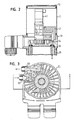
- FIG. 1 Shown in Figure 1 is a generally designated 10 pneumatic Valve drive with an attached on one end face control head 12 and a connected on its other face valve fitting 14.
- the control head 12 is just one example of a variety of pneumatic or electrical / electronic control modules, with the valve drive 10th can be combined.
- the valve actuator has a housing that is substantially is composed of two parts.
- the first housing part comprises a End wall 20 with a molded cylindrical outer wall part 22.
- the second Housing part comprises an end wall 24 with a molded cylindrical Outer wall part 26.
- Between the end walls 20, 24 is a cylindrical Bushing 28 clamped axially.
- Inside the bushing 28 is a piston 30th guided, which at its periphery against the inner surface of the liner 28th is sealed.
- the piston 30 is supported by a on the end wall 20 Compressed spring 32 is applied to the end wall 24 out.
- a Spindle 34 is connected, which carries a valve member 36 at its free end.
- the cylindrical outer wall parts 22, 26 are bolted together and surrounded the bushing 28.
- the outer wall parts 22, 26 are in turn of a cylindrical shell 38 surrounded by a thin-walled stainless steel consists.
- the sheath 38 is axially braced between the end walls 20, 24 and sealed by a seal.
- the sheath 38 connects virtually gap-free the end wall 24 and on the periphery of the end wall 20 at. She gives that Valve drive a high-quality appearance and at the same time meets the high Claims on material properties and shape design used in industrial Areas such as pharmaceutical, biotechnology and food processing.
- control head includes a pneumatic control valve 40 and a pneumatic control block 42. Further, it includes a position sensor 44, which is coaxial with the piston 30 through one of the end wall 20 penetrating coupling clip 46 is connected.
- the end wall 24 forms with its side facing away from the piston 30 end face a uniform interface for connecting various types of Valve fittings.
- a valve-fitting with the Valve body 36 shown for a seat valve for example, a valve-fitting with the Valve body 36 shown for a seat valve.
- Figure 4 shows at 60 the screwing of the outer wall part 22 with the Outer wall part 26, the sealing of these wall parts together by a inserted ring seal 62 and the clamping and sealing of the Bushing 28 with a ring seal 64, which in a groove of the end wall 20th is inserted. Further, the connection of the cylindrical shell 38 at the transition between the end wall 20 and outer wall part 22 with the insertion of a seal 66th to recognize.
- the control head 12 has a similar appearance as the valve drive 10 on.
- he also has a cylindrical shell 70, which consists of a thin-walled stainless steel. It is between the end wall 20 and an opposite cover 72 clamped axially.
- the lid 72 can directly to the end wall 20th be attached, which also forms a suitable interface for this cover 72, as shown in FIG.
Landscapes
- Engineering & Computer Science (AREA)
- General Engineering & Computer Science (AREA)
- Mechanical Engineering (AREA)
- Actuator (AREA)
- Fluid-Driven Valves (AREA)
- Valve Housings (AREA)
- Multiple-Way Valves (AREA)
Priority Applications (1)
| Application Number | Priority Date | Filing Date | Title |
|---|---|---|---|
| EP06000177A EP1643175B1 (fr) | 2003-08-06 | 2004-07-28 | Actionneur pneumatique d'une soupape |
Applications Claiming Priority (2)
| Application Number | Priority Date | Filing Date | Title |
|---|---|---|---|
| DE10336065 | 2003-08-06 | ||
| DE10336065A DE10336065A1 (de) | 2003-08-06 | 2003-08-06 | Pneumatischer Ventilantrieb |
Related Child Applications (1)
| Application Number | Title | Priority Date | Filing Date |
|---|---|---|---|
| EP06000177A Division EP1643175B1 (fr) | 2003-08-06 | 2004-07-28 | Actionneur pneumatique d'une soupape |
Publications (2)
| Publication Number | Publication Date |
|---|---|
| EP1505325A1 true EP1505325A1 (fr) | 2005-02-09 |
| EP1505325B1 EP1505325B1 (fr) | 2006-11-15 |
Family
ID=33547108
Family Applications (2)
| Application Number | Title | Priority Date | Filing Date |
|---|---|---|---|
| EP20040017860 Expired - Lifetime EP1505325B1 (fr) | 2003-08-06 | 2004-07-28 | Actionneur pneumatique d'une soupape |
| EP06000177A Expired - Lifetime EP1643175B1 (fr) | 2003-08-06 | 2004-07-28 | Actionneur pneumatique d'une soupape |
Family Applications After (1)
| Application Number | Title | Priority Date | Filing Date |
|---|---|---|---|
| EP06000177A Expired - Lifetime EP1643175B1 (fr) | 2003-08-06 | 2004-07-28 | Actionneur pneumatique d'une soupape |
Country Status (2)
| Country | Link |
|---|---|
| EP (2) | EP1505325B1 (fr) |
| DE (3) | DE10336065A1 (fr) |
Cited By (5)
| Publication number | Priority date | Publication date | Assignee | Title |
|---|---|---|---|---|
| EP2016318A1 (fr) | 2006-05-10 | 2009-01-21 | GEA Tuchenhagen GmbH | Structure modulaire de boitier pour des systemes de surveillance, de commande et de regulation pour une soupape de processus |
| EP2292959A3 (fr) * | 2009-09-08 | 2014-05-07 | Bürkert Werke GmbH | Module de commande |
| EP3096054A1 (fr) * | 2015-05-19 | 2016-11-23 | Gemü Gebr. Müller Apparatebau Gmbh & Co. Kommanditgesellschaf | Actionneur de vanne |
| DE102018217986B3 (de) | 2018-10-22 | 2019-09-05 | Festo Ag & Co. Kg | Pneumatiksteller |
| EP4545829A1 (fr) | 2023-10-23 | 2025-04-30 | SISTO Armaturen S.A. | Boîte d'interrupteur de fin de course à concept pneumatique |
Families Citing this family (15)
| Publication number | Priority date | Publication date | Assignee | Title |
|---|---|---|---|---|
| CN100540961C (zh) * | 2007-12-14 | 2009-09-16 | 苏州有色金属研究院有限公司 | 气缸式喷射阀 |
| DE102008023748B4 (de) | 2008-05-15 | 2011-01-20 | Armaturenwerk Hötensleben GmbH | Steuerkopf und Dichtung für einen pneumatischen Antrieb |
| DE202010003659U1 (de) | 2010-03-16 | 2010-07-15 | Bürkert Werke GmbH | Vorrichtung zur Endlagenerkennung in Hubventilen, Ventilbausatz sowie Sensormodul hierfür |
| DE102010050662A1 (de) | 2010-11-09 | 2012-05-10 | Festo Ag & Co. Kg | Steuerkopf für ein fluidisch ansteuerbares Ventil |
| DE102012003230B3 (de) * | 2012-02-20 | 2013-03-21 | Festo Ag & Co. Kg | Prozessventil |
| DE102012003231B3 (de) * | 2012-02-20 | 2013-03-21 | Festo Ag & Co. Kg | Prozessventil |
| DE202012002019U1 (de) | 2012-02-27 | 2012-04-03 | Bürkert Werke GmbH | Manuell betätigbares Ansteuermodul |
| DE102014004669B3 (de) * | 2014-03-31 | 2015-09-24 | Festo Ag & Co. Kg | Ventil |
| DE102014013390A1 (de) | 2014-09-11 | 2016-03-17 | Festo Ag & Co. Kg | Pneumatischer Ventilantrieb |
| DE102014013391B4 (de) | 2014-09-11 | 2019-07-04 | Festo Ag & Co. Kg | Ventilbetätigungssystem |
| DE102016200396B3 (de) | 2016-01-14 | 2016-08-25 | Festo Ag & Co. Kg | Ventilbetätigungssystem |
| DE102016214252A1 (de) * | 2016-08-02 | 2018-02-08 | Festo Ag & Co. Kg | Ventilbetätigungssystem |
| US10180197B1 (en) | 2017-09-07 | 2019-01-15 | Honeywell International Inc. | Protective housing for configuring a programming module of an industrial product |
| DE102017123376B4 (de) | 2017-10-09 | 2024-06-06 | Bürkert Werke GmbH & Co. KG | Ventilantriebssystem für ein pneumatisches oder hydraulisches Ventil |
| WO2022020771A1 (fr) | 2020-07-24 | 2022-01-27 | Schneider Electric USA, Inc. | Dispositif neutre enfichable d'entrée de service |
Citations (2)
| Publication number | Priority date | Publication date | Assignee | Title |
|---|---|---|---|---|
| DE19641073A1 (de) * | 1996-10-04 | 1998-04-16 | Adolf Harald Sonnleitner | Druckmittelbetätigbares Ventil |
| US20010028049A1 (en) * | 2000-04-11 | 2001-10-11 | Ckd Corporation | High-temperature gas control valve |
Family Cites Families (4)
| Publication number | Priority date | Publication date | Assignee | Title |
|---|---|---|---|---|
| GB9004391D0 (en) * | 1990-02-27 | 1990-04-25 | Timmins John A | Simplified valve control |
| DE9307166U1 (de) * | 1993-05-11 | 1993-07-15 | Bürkert GmbH & Co Werk Ingelfingen, 7118 Ingelfingen | Sperrventil |
| US6086040A (en) * | 1997-11-07 | 2000-07-11 | Apv Fluid Handling Horsens A/S | Valve and a pneumatic control valve non-rotatably joined by a coupling |
| JP3553526B2 (ja) * | 2001-06-27 | 2004-08-11 | 株式会社キッツエスシーティー | 可変流量バルブ |
-
2003
- 2003-08-06 DE DE10336065A patent/DE10336065A1/de not_active Withdrawn
-
2004
- 2004-07-28 EP EP20040017860 patent/EP1505325B1/fr not_active Expired - Lifetime
- 2004-07-28 EP EP06000177A patent/EP1643175B1/fr not_active Expired - Lifetime
- 2004-07-28 DE DE200450012179 patent/DE502004012179D1/de not_active Expired - Lifetime
- 2004-07-28 DE DE200450001990 patent/DE502004001990D1/de not_active Expired - Lifetime
Patent Citations (2)
| Publication number | Priority date | Publication date | Assignee | Title |
|---|---|---|---|---|
| DE19641073A1 (de) * | 1996-10-04 | 1998-04-16 | Adolf Harald Sonnleitner | Druckmittelbetätigbares Ventil |
| US20010028049A1 (en) * | 2000-04-11 | 2001-10-11 | Ckd Corporation | High-temperature gas control valve |
Cited By (5)
| Publication number | Priority date | Publication date | Assignee | Title |
|---|---|---|---|---|
| EP2016318A1 (fr) | 2006-05-10 | 2009-01-21 | GEA Tuchenhagen GmbH | Structure modulaire de boitier pour des systemes de surveillance, de commande et de regulation pour une soupape de processus |
| EP2292959A3 (fr) * | 2009-09-08 | 2014-05-07 | Bürkert Werke GmbH | Module de commande |
| EP3096054A1 (fr) * | 2015-05-19 | 2016-11-23 | Gemü Gebr. Müller Apparatebau Gmbh & Co. Kommanditgesellschaf | Actionneur de vanne |
| DE102018217986B3 (de) | 2018-10-22 | 2019-09-05 | Festo Ag & Co. Kg | Pneumatiksteller |
| EP4545829A1 (fr) | 2023-10-23 | 2025-04-30 | SISTO Armaturen S.A. | Boîte d'interrupteur de fin de course à concept pneumatique |
Also Published As
| Publication number | Publication date |
|---|---|
| EP1643175B1 (fr) | 2011-02-09 |
| EP1643175A2 (fr) | 2006-04-05 |
| EP1643175A3 (fr) | 2009-03-11 |
| EP1505325B1 (fr) | 2006-11-15 |
| DE502004001990D1 (de) | 2006-12-28 |
| DE502004012179D1 (de) | 2011-03-24 |
| DE10336065A1 (de) | 2005-03-03 |
Similar Documents
| Publication | Publication Date | Title |
|---|---|---|
| EP1643175B1 (fr) | Actionneur pneumatique d'une soupape | |
| DE69708598T2 (de) | Brennstoffeinspritzventilbefestigung für geformte einlasskrümmer mit integrierter brennstoffleitung | |
| EP0866221A1 (fr) | Distributeur de carburant pour un moteur diesel | |
| DE2751946A1 (de) | Druckmittelverteiler, insbesondere fuer hydraulische fernsteuerungen | |
| EP1361382B1 (fr) | Ensemble de soupapes pour la commande de l'écoulement du matériau dans une installation de revêtement | |
| EP3995330B1 (fr) | Soupape de maintien de pression pour un ressort pneumatique et ressort pneumatique comprenant la soupape de maintien de pression | |
| EP2245277B1 (fr) | Insert de guidage de fluide sous pression destiné à une soupape de commande dans un dispositif d'actionnment hydraulique | |
| DE3338418C2 (fr) | ||
| EP1884629A1 (fr) | Coiffe de tête de cylindre | |
| DE3128523A1 (de) | Zylinderkopf fuer einen verbrennungsmotor | |
| DE102009027273A1 (de) | Hochdruckpumpe | |
| DE29518188U1 (de) | Blocksauger | |
| EP1696159B1 (fr) | Soupape à pince actionnée par fluide | |
| EP1931860A1 (fr) | Soupape de regulation de debit servant a restreindre le passage d'une substance de pression hydraulique | |
| DE19500565B4 (de) | Ventilanordnung | |
| WO2003046353A1 (fr) | Boitier de papillon | |
| DE3722479A1 (de) | Magnetventil | |
| DE102019108261A1 (de) | Druckschaltvorrichtung | |
| DE4438196A1 (de) | Zylinder für fluidische Mittel | |
| EP0987475B1 (fr) | Soupape de pression résiduelle | |
| EP1319884B1 (fr) | Dispositif de raccordement universel | |
| DE10346242B4 (de) | Injektorkörper für einen Common Rail Injektor | |
| DE102019107273A1 (de) | Verbindungsanordnung zwischen einer Steuereinrichtung und einem Anschlussflansch sowie Steuereinrichtung, Anschlussflansch und Befestigungselement für die Verbindungsanordnung | |
| DE4202730C1 (en) | Valve with two part metal housing and piston and elastic seal - has injection moulded plastics insert supporting cast running face associated with piston seal. | |
| DE102009051365A1 (de) | Einheit zum Fördern von Druckfluid und Verfahren zur Herstellung |
Legal Events
| Date | Code | Title | Description |
|---|---|---|---|
| PUAI | Public reference made under article 153(3) epc to a published international application that has entered the european phase |
Free format text: ORIGINAL CODE: 0009012 |
|
| AK | Designated contracting states |
Kind code of ref document: A1 Designated state(s): AT BE BG CH CY CZ DE DK EE ES FI FR GB GR HU IE IT LI LU MC NL PL PT RO SE SI SK TR |
|
| AX | Request for extension of the european patent |
Extension state: AL HR LT LV MK |
|
| EL | Fr: translation of claims filed | ||
| GBC | Gb: translation of claims filed (gb section 78(7)/1977) | ||
| 17P | Request for examination filed |
Effective date: 20050523 |
|
| AKX | Designation fees paid |
Designated state(s): CH DE FR GB IT LI |
|
| GRAP | Despatch of communication of intention to grant a patent |
Free format text: ORIGINAL CODE: EPIDOSNIGR1 |
|
| GRAS | Grant fee paid |
Free format text: ORIGINAL CODE: EPIDOSNIGR3 |
|
| GRAA | (expected) grant |
Free format text: ORIGINAL CODE: 0009210 |
|
| AK | Designated contracting states |
Kind code of ref document: B1 Designated state(s): CH DE FR GB IT LI |
|
| REG | Reference to a national code |
Ref country code: GB Ref legal event code: FG4D Free format text: NOT ENGLISH |
|
| REG | Reference to a national code |
Ref country code: CH Ref legal event code: NV Representative=s name: BUGNION S.A. Ref country code: CH Ref legal event code: EP |
|
| REF | Corresponds to: |
Ref document number: 502004001990 Country of ref document: DE Date of ref document: 20061228 Kind code of ref document: P |
|
| GBT | Gb: translation of ep patent filed (gb section 77(6)(a)/1977) |
Effective date: 20070117 |
|
| ET | Fr: translation filed | ||
| PLBE | No opposition filed within time limit |
Free format text: ORIGINAL CODE: 0009261 |
|
| STAA | Information on the status of an ep patent application or granted ep patent |
Free format text: STATUS: NO OPPOSITION FILED WITHIN TIME LIMIT |
|
| 26N | No opposition filed |
Effective date: 20070817 |
|
| REG | Reference to a national code |
Ref country code: CH Ref legal event code: PFA Owner name: UERKERT WERKE GMBH Free format text: BUERKERT WERKE GMBH & CO. KG#CHRISTIAN-BUERKERT-STRASSE 13-17#74653 INGELFINGEN (DE) -TRANSFER TO- BUERKERT WERKE GMBH#CHRISTIAN-BUERKERT-STRASSE 13-17#74653 INGELFINGEN (DE) |
|
| REG | Reference to a national code |
Ref country code: GB Ref legal event code: 732E Free format text: REGISTERED BETWEEN 20100422 AND 20100428 |
|
| REG | Reference to a national code |
Ref country code: FR Ref legal event code: CD |
|
| PGFP | Annual fee paid to national office [announced via postgrant information from national office to epo] |
Ref country code: CH Payment date: 20130719 Year of fee payment: 10 |
|
| REG | Reference to a national code |
Ref country code: CH Ref legal event code: PL |
|
| PG25 | Lapsed in a contracting state [announced via postgrant information from national office to epo] |
Ref country code: CH Free format text: LAPSE BECAUSE OF NON-PAYMENT OF DUE FEES Effective date: 20140731 Ref country code: LI Free format text: LAPSE BECAUSE OF NON-PAYMENT OF DUE FEES Effective date: 20140731 |
|
| REG | Reference to a national code |
Ref country code: FR Ref legal event code: PLFP Year of fee payment: 13 |
|
| REG | Reference to a national code |
Ref country code: FR Ref legal event code: PLFP Year of fee payment: 14 |
|
| REG | Reference to a national code |
Ref country code: FR Ref legal event code: PLFP Year of fee payment: 15 |
|
| PGFP | Annual fee paid to national office [announced via postgrant information from national office to epo] |
Ref country code: IT Payment date: 20180724 Year of fee payment: 15 |
|
| PGFP | Annual fee paid to national office [announced via postgrant information from national office to epo] |
Ref country code: GB Payment date: 20180719 Year of fee payment: 15 |
|
| GBPC | Gb: european patent ceased through non-payment of renewal fee |
Effective date: 20190728 |
|
| PG25 | Lapsed in a contracting state [announced via postgrant information from national office to epo] |
Ref country code: GB Free format text: LAPSE BECAUSE OF NON-PAYMENT OF DUE FEES Effective date: 20190728 |
|
| PG25 | Lapsed in a contracting state [announced via postgrant information from national office to epo] |
Ref country code: IT Free format text: LAPSE BECAUSE OF NON-PAYMENT OF DUE FEES Effective date: 20190728 |
|
| P01 | Opt-out of the competence of the unified patent court (upc) registered |
Effective date: 20230523 |
|
| PGFP | Annual fee paid to national office [announced via postgrant information from national office to epo] |
Ref country code: FR Payment date: 20230725 Year of fee payment: 20 Ref country code: DE Payment date: 20230725 Year of fee payment: 20 |
|
| REG | Reference to a national code |
Ref country code: DE Ref legal event code: R071 Ref document number: 502004001990 Country of ref document: DE |