EP1510150B1 - Angle-adjustable hinge - Google Patents
Angle-adjustable hinge Download PDFInfo
- Publication number
- EP1510150B1 EP1510150B1 EP04006535A EP04006535A EP1510150B1 EP 1510150 B1 EP1510150 B1 EP 1510150B1 EP 04006535 A EP04006535 A EP 04006535A EP 04006535 A EP04006535 A EP 04006535A EP 1510150 B1 EP1510150 B1 EP 1510150B1
- Authority
- EP
- European Patent Office
- Prior art keywords
- arm
- angle
- gear portion
- face
- wedge
- Prior art date
- Legal status (The legal status is an assumption and is not a legal conclusion. Google has not performed a legal analysis and makes no representation as to the accuracy of the status listed.)
- Expired - Lifetime
Links
Images





Classifications
-
- A—HUMAN NECESSITIES
- A47—FURNITURE; DOMESTIC ARTICLES OR APPLIANCES; COFFEE MILLS; SPICE MILLS; SUCTION CLEANERS IN GENERAL
- A47C—CHAIRS; SOFAS; BEDS
- A47C3/00—Chairs characterised by structural features; Chairs or stools with rotatable or vertically-adjustable seats
- A47C3/16—Chairs characterised by structural features; Chairs or stools with rotatable or vertically-adjustable seats of legless type, e.g. with seat directly resting on the floor; Hassocks; Pouffes
-
- A—HUMAN NECESSITIES
- A47—FURNITURE; DOMESTIC ARTICLES OR APPLIANCES; COFFEE MILLS; SPICE MILLS; SUCTION CLEANERS IN GENERAL
- A47C—CHAIRS; SOFAS; BEDS
- A47C1/00—Chairs adapted for special purposes
- A47C1/02—Reclining or easy chairs
- A47C1/022—Reclining or easy chairs having independently-adjustable supporting parts
- A47C1/024—Reclining or easy chairs having independently-adjustable supporting parts the parts, being the back-rest, or the back-rest and seat unit, having adjustable inclination
- A47C1/026—Reclining or easy chairs having independently-adjustable supporting parts the parts, being the back-rest, or the back-rest and seat unit, having adjustable inclination by means of a peg-and-notch or pawl-and-ratchet mechanism
-
- A—HUMAN NECESSITIES
- A47—FURNITURE; DOMESTIC ARTICLES OR APPLIANCES; COFFEE MILLS; SPICE MILLS; SUCTION CLEANERS IN GENERAL
- A47C—CHAIRS; SOFAS; BEDS
- A47C1/00—Chairs adapted for special purposes
- A47C1/14—Beach chairs ; Chairs for outdoor use, e.g. chairs for relaxation or sun-tanning
- A47C1/146—Beach chairs ; Chairs for outdoor use, e.g. chairs for relaxation or sun-tanning of legless type
-
- E—FIXED CONSTRUCTIONS
- E05—LOCKS; KEYS; WINDOW OR DOOR FITTINGS; SAFES
- E05D—HINGES OR SUSPENSION DEVICES FOR DOORS, WINDOWS OR WINGS
- E05D11/00—Additional features or accessories of hinges
- E05D11/10—Devices for preventing movement between relatively-movable hinge parts
- E05D11/1007—Devices for preventing movement between relatively-movable hinge parts with positive locking
-
- E—FIXED CONSTRUCTIONS
- E05—LOCKS; KEYS; WINDOW OR DOOR FITTINGS; SAFES
- E05D—HINGES OR SUSPENSION DEVICES FOR DOORS, WINDOWS OR WINGS
- E05D7/00—Hinges or pivots of special construction
- E05D7/0009—Adjustable hinges
-
- E—FIXED CONSTRUCTIONS
- E05—LOCKS; KEYS; WINDOW OR DOOR FITTINGS; SAFES
- E05Y—INDEXING SCHEME ASSOCIATED WITH SUBCLASSES E05D AND E05F, RELATING TO CONSTRUCTION ELEMENTS, ELECTRIC CONTROL, POWER SUPPLY, POWER SIGNAL OR TRANSMISSION, USER INTERFACES, MOUNTING OR COUPLING, DETAILS, ACCESSORIES, AUXILIARY OPERATIONS NOT OTHERWISE PROVIDED FOR, APPLICATION THEREOF
- E05Y2900/00—Application of doors, windows, wings or fittings thereof
- E05Y2900/10—Application of doors, windows, wings or fittings thereof for buildings or parts thereof
- E05Y2900/13—Type of wing
- E05Y2900/148—Windows
Definitions
- This invention relates to an angle-adjustable hinge as a joint member with which an angle formed by members on one side and another side can be freely set.
- An adjustable hinge is known from US 5 474 360.
- a legless chair having a back 15 and a seat 16 as shown in a perspective view of Figure 1 is provided with a hinge between the back 15 and the seat 16 having angle-adjusting function to adjust an inclination angle of the back 15, namely, an angle-adjustable hinge A.
- This conventional hinge is constructed as that a gear and a claw piece of a second arm on another side (the back 15 side) are held in a case portion of a first arm connected to one side (the seat 16 side) to restrict oscillation of the second arm in an extending direction (reclining direction of the back 15) to the first arm by engagement of the claw piece with the gear (refer to Japanese utility model publication No. 59-20118).
- the claw piece and teeth of the gear are large, and pitch of the teeth of the gear is rough because force working between the first arm and the second arm (force necessary to restrict the oscillation) is to be very large to support man's weight. That is to say, the claw piece and the gear can not be small because of necessary strength.
- angle-adjustable hinge including the features of claim 1. Furthermore detailed embodiments are described in dependent claims 2, 3, 4, and 5.
- An angle-adjustable hinge relating to the present invention is, for example, in a legless chair having a back 15 and a seat 16 as shown in a perspective view of Figure 1, disposed between the back 15 and the seat 16 to adjust inclination angle of the back 15. That is to say, this angle-adjustable hinge A is a joint hinge (connecting hinge) having angle-adjusting function.
- the hinge A can be used for a sofa, a head rest, a foot rest, etc. other than the legless chair, assembled with two oscillating members, and also used for shelves of which doors are opened and closed by oscillation.
- Figure 2 is a perspective view of the angle-adjustable hinge A
- Figure 3 is an exploded perspective view of the same.
- the angle-adjustable hinge A of the present invention is provided with a first arm 1 provided with a case portion 3 and a second arm 2, connected to the first arm 1 as to oscillate around a first axis C 1 by the case portion 3 and provided with a gear portion 4 of which center is the first axis C 1 . That is to say, the first arm 1 and the second arm 2 are connected as to mutually oscillate around the first axis C 1 as the center.
- the first arm 1 has the case portion 3 having a pair of wall portions 17 facing each other, and a first attachment portion 18 extended from the case portion 3.
- the first attachment portion 18 has a cylindrical configuration in Figure 1 to be inserted for fixation.
- the second arm 2 has the gear portion 4 stored in the above case portion 3, and a second attachment portion 19 extended from the gear portion 4.
- the second attachment portion 19 has a cylindrical configuration in Figure 1 to be inserted for fixation.
- the gear portion 4 is formed along an arc line of which center is the first axis C 1 , and having gear (teeth) within a range (of 100 to 120 ° ) over a quarter circle (90 °) slightly (10 to 30° ) as shown in Figure 3.
- the first and the second attachment portions 18 and 19 may be connected with bolts or have other configurations.
- a frame of the seat 16 is attached to the first attachment portion 18 of the first arm 1
- a frame of the back 15 is attached to the second attachment portion 19 of the second arm 2
- the back 15 oscillates in respect to the seat 16, and the back 15 is reclined and held with a desired inclination angle.
- connection of the first arm 1 and the second arm 2 is made with a shaft member 20 as shown in Figure 2 and Figure 3.
- a through hole 21 is formed on a central portion of each of the wall portions 17 of the case portion 3 of the first arm 1, a through hole 22 of which center is the first axis C 1 is formed on the gear portion 4 of the second arm 2, and the shaft member 20 is inserted to the through holes 21 and 22 as the wall portions 17 surround the gear portion 4 to let the first and the second arms 1 and 2 oscillate around the first axis C 1 .
- angle-adjustable hinge A is provided with a wedge-shaped window portion 5 formed on the case portion 3 of the first arm 1.
- the wedge-shaped window portion 5 is formed on each of the wall portions 17 of the case portion 3 as to have the same configuration and penetrate the case portion 3.
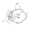
- FIG 4 is an explanatory view of a principal portion of the angle-adjustable hinge A.
- the wedge-shaped window portion 5 is a through hole formed arc-shaped to be concave to the first axis C 1 side, an arc-shaped wedge face 8, on a position outer to the gear portion 4, is formed on an outer side face of the through hole when the first axis C 1 is on the center side, and an arc face 23, of which center is the first axis C 1 and smaller than the gear portion 4, is formed on an inner side face. Therefore, the teeth of the gear portion 4 are observed through the wedge-shaped window portion 5.
- the wedge face 8 is formed arc-shaped of which center is a second axis C 2 eccentric to the first axis C 1 .
- the wedge-shaped window portion 5 becomes a wedge-shaped hole diminishing to clockwise direction, namely, the wedge face 8 approaches the gear portion 4.
- a space is formed between the wedge face 8 and a peripheral toothed face of the gear portion 4, and a later-described floating wedge member 6 is disposed in the space.
- angle-adjustable hinge A is provided with the floating wedge member 6 which is disposed movably within the wedge-shaped window portion 5, of which one face (an inner side face) is a toothed face 7 to engage with the gear portion 4, and another face (an outer side face) is a contact face 9 to contact the wedge face 8.
- the contact face 9 has a radius of curvature (approximately) similar to that of the wedge face 8.
- plural teeth are formed on a face identical to a pitch face of the gear portion 4, and all of the teeth engage with the gear portion 4 at the same time.
- Width dimension of the floating wedge member 6 is approximately same as that of the case portion 3. Therefore, both of edge faces of the contact face 9 of the floating wedge member 6 can contact the wedge face 8 of the wedge-shaped window portion 5 (the side walls 17).
- number of the teeth of the gear portion 4 of the second arm 2 is 12 to 24 for a quarter circle (90° ) of the gear portion 4
- number of the teeth of the toothed face 7 of the floating wedge member 6 is 3 to 9.
- the number of the teeth of the gear portion 4 is 18 for the quarter circle, the teeth are formed within a range of 110° , and the number of the teeth is 22 in all.
- the number of the teeth of the floating wedge member 6 is 6.
- the teeth of the gear portion 4 and the floating wedge member 6 are set to have a 5° pitch.
- the case portion 3 of the first arm 1 has an elastic member 13 to elastically push the floating wedge member 6 to the gear portion 4 of the second arm 2.
- the elastic member 13 is a spring member formed with a steel wire bent U-shaped, of which both ends are fixed to the case portion 3 between the wall portions 17 and a central portion contacts a central area of the contact face 9 of the floating wedge member 6, and elastically pushing the floating wedge member 6 to the gear portion 4.
- the floating wedge member 6 has a falling-prevention means to prevent falling out of the window portion 5 because the floating wedge member 6 is disposed movably within the wedge-shaped window portion 5.
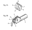
- Figures 5A and 5B are explanatory views of the falling-prevention means. To describe the falling-prevention means concretely, a hitching portion 14, hitching to the elastic member 13 to prevent falling out of the wedge-shaped window portion 5, is formed on the floating wedge member 6.
- the hitching portion 14 is, as shown in Figure 5A, a rising portion 24 formed higher than the contact face 9 of the floating wedge member 6 for one stage, and two wire portions of the elastic member bent to be U-shaped hold the rising portion 24 as shown in Figure 5B.
- FIGs 6A and 6B are explanatory views of another embodiment of the falling-prevention means.
- Two concave grooves 25 are formed on the contact face 9 as the hitching portion 14 as shown in Figure 6A, and two wire portions of the elastic member bent to be U-shaped fit to the concave grooves 25 as shown in Figure 6B.
- the hitching portion 14 hitches to the elastic member 13 fixed to the case portion 3 to prevent the floating wedge member 6 from falling out of the wedge-shaped window portion 5.
- a lid member of thin plate may be attached to both of the outer sides of the case portion 3 to cover the wedge-shaped window portions 5.
- the lid member is constructed as to insert and hold the shaft member 20 (refer to Figure 3).
- a cover 26 to prevent foreign matter intrusion is attached to the case portion 3.
- the cover 26 is disposed between the wall portions 17 as to cover the gear portion 4 and the floating wedge member 6 engaged with the gear portion 4 to prevent the floating wedge member 6 from being stuck by the foreign matter intrusion.
- Figures 7 through 11 are front views of the angle-adjustable hinge A to explain the movement in which the wall portion 17 on one side (the front side) of the case portion 3 is partially vanished (omitted) for explanation.
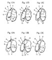
- Figures 12A through 13C are front views of a principal portion to explain the movements of the gear portion 4 and the floating wedge member 6 within the wedge-shaped window portion 5.
- the guiding slope 27 of the floating wedge member 6 is formed on a rear end portion of the toothed face 7 of the floating wedge member 6, and the staged portion 28 of the wedge-shaped window portion 5 is formed on the arc face 23 on an inner side of the wedge-shaped window portion 5 as to contact the slope 27.
- the floating wedge member 6 restricts the second arm 2 not to oscillate in the extending direction toward the first arm 1by wedge function of the floating wedge member 6, of which the toothed face 7 engages with the gear portion 4 and the contact face 9 contacts the wedge face 8, held between the gear portion 4 and the wedge face 8.
- first arm 1 and the second arm 2 can be maintained as to form a desired folding angle (inclination angle).
- the second arm 2 has a push-back protrusion 10 to push the floating wedge member 6 in the folding direction when the second arm 2 oscillates toward the first arm 1 beyond a predetermined folding angle to become the full-folded state (Figure 9).
- the push-back protrusion 10 is formed on an end portion side of the gear portion 4 (toothed portion) to contact the front end portion of the toothed face 7 of the floating wedge member 6.
- the second arm 2 becomes free (freely oscillatable) in respect of the first arm 1, freely oscillatable in the extending direction as shown in Figure 11, and returnable to the full-extended state in Figure 7.
- the second arm 2 has a pushing protrusion 12 to push the floating wedge member 6 stored in the retreat space 11 to engage the toothed face 7 with the gear portion 4 as shown in Figure 13C when the second arm 2 is oscillated to the full-extended state of the predetermined angle (180° ) to the first arm 1.
- the pushing protrusion 12 is formed on another end portion side (opposite to the end portion side on which the push-back protrusion 10 is formed) of the gear portion 4.
- the protrusion 12 pushes the guiding slope 27 of the floating wedge member 6 to push the floating wedge member 6 out of the retreat space 11 and return to the state of Figure 12A.
- the movement of the floating wedge member 6 within the wedge-shaped window portion 5 is as follows. From the full-extended state to the full-folded state, the floating wedge member 6 is held by the gear portion 4 and the wedge face 8 to adjust and maintain the desired folding angle (inclination angle) of the first arm 1 on the wedge face 8 side and the second arm 2 on the gear portion 4 side. Beyond the full-folded state, the floating wedge member 6 is pushed by the push-back protrusion 10 and stored in the retreat space 11 in the wedge-shaped window portion 5 to make the first arm 1 and the second arm 2 freely oscillatable.
- the second arm 2 is oscillated only for a small oscillation angle (about 15° ) from the full-folded state (inclined at 80° ) to make the second arm 2 fully extended because the pitch of the teeth of the gear portion 4 is small, and the engagement with the gear portion 4 is released only by the movement of the floating wedge member 6 within the wedge-shaped window portion 5.
- the back 15 can not be returned to horizontal state without a large forward bend (of 17 ° from the vertical line) with the conventional hinge A, and user's body receives high stress when the angle is changed while the user is sitting in the chair.
- the back 15 is bent forward slightly (for 5° ) to reduce the stress and make the operation comfortable.
- adjusting pitch of the folding angle (inclination angle) is, for example, 5 ° in the present invention and the angle can be adjusted from 0 ° to 80 ° with 17 stages
- the adjusting pitch of the folding angle (inclination angle) of the conventional hinge is 16° and the angle is adjusted from 0° to 80 ° only with 6 stages.
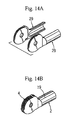
- half arm members 29 are made by die plastic work, etc. as shown in Figure 14A, and then, these are assembled by welding, etc. to compose the second arm 2 as shown in Figure 14B.
- gear portion 4 and an arm portion 30 may be separately made by die plastic work, etc. to be assembled.
- the second arm 2 may be unitedly formed by die plastic work, etc.(through plural production processes).
- a multi-staged angle-adjustable hinge (a ratchet gear portion) infinitely close to stepless can be composed, keeping the strength, by enlarging the radius of curvature of the pitch circle of the gear with the tooth (a module) remaining as it is.
- the both of the first arm 1 and the second arm 2 never oscillate in the extending direction because the contact face 9 on the outer side of the floating wedge member 6 contacts the wedge face 8 of the wedge-shaped window portion 5 and pressing force toward the center of the gear portion 4 works through the floating wedge member 6 engaging with the gear portion 4 when the first arm 1 and the second arm 2 are about to oscillate in the extending direction, with the construction in which the first arm 1 is provided with the case portion 3, the second arm 2 is connected to the first arm 1 as to oscillate around the first axis C 1 and provided with the gear portion 4, the wedge-shaped window portion 5 is formed on the case portion 3 of the first arm 1, and the floating wedge member 6, disposed movably within the wedge-shaped window portion 5, of which one face side is the toothed face 7 to engage with the gear portion 4 and another face side is the contact face 9 to contact the wedge face 8 on the outer side of the wedge-shaped window portion 5 to restrict the second arm 2 to oscillate in the extending direction with respect to the first arm 1.
- the tooth (module) of the gear portion 4 in spite of its small size, can receive high load and have sufficient strength because the oscillation is restricted not only by hitching of the gear portion 4 but by contact force of the floating wedge member 6 to the wedge face 8, the engagement of the gear portion 4, and the pressing force.
- the number of the teeth on the gear portion 4 can be increased by making the tooth of the gear portion 4 small to increase the number of angle-adjusting stages. Therefore, the pitch of the folding angle becomes small for fine adjustment. That is to say, the back 15 of comfortable inclination angle is obtained when the hinge is applied to chairs and sofas.
- the whole hinge can be made small by the small composition of the case portion 3, and a cover of a chair or a sofa is not damaged when the hinge A is disposed inside the cover.
- the engagement with the gear portion 4 is released and reengaged by the movement of the floating wedge member 6 within the wedge-shaped window portion 5 to greatly facilitate the angle-adjusting movement of the first arm 1 and the second arm 2 because the second arm 2 has the push-back protrusion 10 to push the floating wedge member 6 in the folding direction when the second arm 2 oscillates to the first arm 1 over a predetermined folding angle, the wedge-shaped window portion 5 has the retreat space 11 for storing the floating wedge member 6 pushed-back by the push-back protrusion 10 to release the engagement of the toothed face 7 and the gear portion 4, and the second arm 2 has the pushing protrusion 12 for pushing the floating wedge member 6 stored in the retreat space 11 to make the toothed face 7 engage with the gear portion 4 when the second arm 2 is oscillated to open with respect to the first arm 1.
- the number of angle-adjusting stages is increased, and high load working on the first arm and the second arm 2 is stably received because the number of the teeth of the gear portion 4 of the second arm 2 is 12 to 24 for a quarter circle of the gear portion 4, and the number of the teeth of the toothed face 7 of the floating wedge member 6 is 3 to 9.
Landscapes
- Health & Medical Sciences (AREA)
- Dentistry (AREA)
- General Health & Medical Sciences (AREA)
- Engineering & Computer Science (AREA)
- Mechanical Engineering (AREA)
- Chairs For Special Purposes, Such As Reclining Chairs (AREA)
- Pivots And Pivotal Connections (AREA)
- Hinges (AREA)
- Superstructure Of Vehicle (AREA)
Description
- This invention relates to an angle-adjustable hinge as a joint member with which an angle formed by members on one side and another side can be freely set. An adjustable hinge is known from US 5 474 360.
- A legless chair having a
back 15 and aseat 16 as shown in a perspective view of Figure 1 is provided with a hinge between theback 15 and theseat 16 having angle-adjusting function to adjust an inclination angle of theback 15, namely, an angle-adjustable hinge A. - This conventional hinge is constructed as that a gear and a claw piece of a second arm on another side (the
back 15 side) are held in a case portion of a first arm connected to one side (theseat 16 side) to restrict oscillation of the second arm in an extending direction (reclining direction of the back 15) to the first arm by engagement of the claw piece with the gear (refer to Japanese utility model publication No. 59-20118). - In the conventional hinge, the claw piece and teeth of the gear are large, and pitch of the teeth of the gear is rough because force working between the first arm and the second arm (force necessary to restrict the oscillation) is to be very large to support man's weight. That is to say, the claw piece and the gear can not be small because of necessary strength.
- Therefore, the case portion for storing the claw piece and the gear becomes large, number of the teeth of the gear is small (the pitch is large), and fine adjustment is impossible for small number of angle change stages.
- It is an object of the present invention to provide an angle-adjustable hinge with which the number of angle change stages is made large and the entire hinge is made small with small components.
- This object is solved according to the present invention by angle-adjustable hinge including the features of
claim 1. Furthermore detailed embodiments are described independent claims - The present invention will be described with reference to the accompanying drawings, in which:
- Figure 1 is a perspective view of a legless chair having angle-adjustable hinges of the present invention;
- Figure 2 is a perspective view of the angle-adjustable hinge;
- Figure 3 is an exploded perspective view of the angle-adjustable hinge;
- Figure 4 is an explanatory view of a floating wedge member, a gear portion, and a wedge-shaped window portion;
- Figure 5A is an explanatory view of falling-prevention means of the floating wedge member;
- Figure 5B is an explanatory view of the falling-prevention means of the floating wedge member;
- Figure 6A is an explanatory view of another embodiment of the falling-prevention means of the floating wedge member;
- Figure 6B is an explanatory view of another embodiment of the falling-prevention means of the floating wedge member;
- Figure 7 is a front view of the angle-adjustable hinge in full-extended state;
- Figure 8 is a front view of the angle-adjustable hinge in a desired inclination angle;
- Figure 9 is a front view of the angle-adjustable hinge in full-folded state;
- Figure 10 is a front view of the angle-adjustable hinge in angle retension release state;
- Figure 11 is a front view of the angle-adjustable hinge in a state in which a second arm is returned to the extending direction;
- Figures 12A through 12C are front views of a principal portion to explain angle-setting movement from the full-extended state;
- Figures 13A through 13C are front views of the principal portion to explain returning movement of the second arm from the full-folded state in the extending direction;
- Figure 14A is a perspective view to explain a construction of the second arm;
- Figure 14B is a perspective view to explain the construction of the second arm;
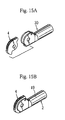
- Figure 15A is a perspective view to explain a construction of the second arm in another embodiment;
- Figure 15B is a perspective view to explain the construction of the second arm in another embodiment;
- Figure 16 is an explanatory view of angle-adjusting function of the present invention; and
- Figure 17 is an explanatory view of angle adjustment of a conventional angle-adjustable hinge.
- Preferred embodiments of the present invention will now be described with reference to the accompanying drawings.
- An angle-adjustable hinge relating to the present invention is, for example, in a legless chair having a
back 15 and aseat 16 as shown in a perspective view of Figure 1, disposed between theback 15 and theseat 16 to adjust inclination angle of theback 15. That is to say, this angle-adjustable hinge A is a joint hinge (connecting hinge) having angle-adjusting function. The hinge A can be used for a sofa, a head rest, a foot rest, etc. other than the legless chair, assembled with two oscillating members, and also used for shelves of which doors are opened and closed by oscillation. - Figure 2 is a perspective view of the angle-adjustable hinge A, and Figure 3 is an exploded perspective view of the same.
- The angle-adjustable hinge A of the present invention is provided with a
first arm 1 provided with acase portion 3 and asecond arm 2, connected to thefirst arm 1 as to oscillate around a first axis C1by thecase portion 3 and provided with agear portion 4 of which center is the first axis C1 . That is to say, thefirst arm 1 and thesecond arm 2 are connected as to mutually oscillate around the first axis C1 as the center. - The
first arm 1 has thecase portion 3 having a pair ofwall portions 17 facing each other, and afirst attachment portion 18 extended from thecase portion 3. Thefirst attachment portion 18 has a cylindrical configuration in Figure 1 to be inserted for fixation. - And, the
second arm 2 has thegear portion 4 stored in theabove case portion 3, and asecond attachment portion 19 extended from thegear portion 4. Thesecond attachment portion 19 has a cylindrical configuration in Figure 1 to be inserted for fixation. - The
gear portion 4 is formed along an arc line of which center is the first axis C1, and having gear (teeth) within a range (of 100 to 120 ° ) over a quarter circle (90 °) slightly (10 to 30° ) as shown in Figure 3. The first and thesecond attachment portions - And, in Figure 1, a frame of the
seat 16 is attached to thefirst attachment portion 18 of thefirst arm 1, a frame of theback 15 is attached to thesecond attachment portion 19 of thesecond arm 2, theback 15 oscillates in respect to theseat 16, and theback 15 is reclined and held with a desired inclination angle. - The connection of the
first arm 1 and thesecond arm 2 is made with ashaft member 20 as shown in Figure 2 and Figure 3. A throughhole 21 is formed on a central portion of each of thewall portions 17 of thecase portion 3 of thefirst arm 1, a throughhole 22 of which center is the first axis C1 is formed on thegear portion 4 of thesecond arm 2, and theshaft member 20 is inserted to the throughholes wall portions 17 surround thegear portion 4 to let the first and thesecond arms - Further, the angle-adjustable hinge A is provided with a wedge-
shaped window portion 5 formed on thecase portion 3 of thefirst arm 1. The wedge-shaped window portion 5 is formed on each of thewall portions 17 of thecase portion 3 as to have the same configuration and penetrate thecase portion 3. - Figure 4 is an explanatory view of a principal portion of the angle-adjustable hinge A. The wedge-
shaped window portion 5 is a through hole formed arc-shaped to be concave to the first axis C1 side, an arc-shaped wedge face 8, on a position outer to thegear portion 4, is formed on an outer side face of the through hole when the first axis C1 is on the center side, and anarc face 23, of which center is the first axis C1 and smaller than thegear portion 4, is formed on an inner side face. Therefore, the teeth of thegear portion 4 are observed through the wedge-shaped window portion 5. - The
wedge face 8 is formed arc-shaped of which center is a second axis C2 eccentric to the first axis C1. When thefirst arm 1 is on the left side and thesecond arm 2 is on the right side as shown in Figure 4, the wedge-shaped window portion 5 becomes a wedge-shaped hole diminishing to clockwise direction, namely, thewedge face 8 approaches thegear portion 4. - A space is formed between the
wedge face 8 and a peripheral toothed face of thegear portion 4, and a later-described floatingwedge member 6 is disposed in the space. - Further, the angle-adjustable hinge A is provided with the floating
wedge member 6 which is disposed movably within the wedge-shaped window portion 5, of which one face (an inner side face) is atoothed face 7 to engage with thegear portion 4, and another face (an outer side face) is acontact face 9 to contact thewedge face 8. - The
contact face 9 has a radius of curvature (approximately) similar to that of thewedge face 8. On thetoothed face 7, plural teeth are formed on a face identical to a pitch face of thegear portion 4, and all of the teeth engage with thegear portion 4 at the same time. - Width dimension of the floating
wedge member 6 is approximately same as that of thecase portion 3. Therefore, both of edge faces of thecontact face 9 of the floatingwedge member 6 can contact thewedge face 8 of the wedge-shaped window portion 5 (the side walls 17). - And, number of the teeth of the
gear portion 4 of thesecond arm 2 is 12 to 24 for a quarter circle (90° ) of thegear portion 4, number of the teeth of thetoothed face 7 of the floatingwedge member 6 is 3 to 9. In Figure 4, the number of the teeth of thegear portion 4 is 18 for the quarter circle, the teeth are formed within a range of 110° , and the number of the teeth is 22 in all. And, the number of the teeth of thefloating wedge member 6 is 6. - That is to say, the teeth of the
gear portion 4 and the floatingwedge member 6 are set to have a 5° pitch. - The
case portion 3 of thefirst arm 1 has anelastic member 13 to elastically push the floatingwedge member 6 to thegear portion 4 of thesecond arm 2. Theelastic member 13 is a spring member formed with a steel wire bent U-shaped, of which both ends are fixed to thecase portion 3 between thewall portions 17 and a central portion contacts a central area of thecontact face 9 of the floatingwedge member 6, and elastically pushing the floatingwedge member 6 to thegear portion 4. - And, the floating
wedge member 6 has a falling-prevention means to prevent falling out of thewindow portion 5 because the floatingwedge member 6 is disposed movably within the wedge-shapedwindow portion 5. Figures 5A and 5B are explanatory views of the falling-prevention means. To describe the falling-prevention means concretely, a hitchingportion 14, hitching to theelastic member 13 to prevent falling out of the wedge-shapedwindow portion 5, is formed on the floatingwedge member 6. - The hitching
portion 14 is, as shown in Figure 5A, a risingportion 24 formed higher than thecontact face 9 of the floatingwedge member 6 for one stage, and two wire portions of the elastic member bent to be U-shaped hold the risingportion 24 as shown in Figure 5B. - Figures 6A and 6B are explanatory views of another embodiment of the falling-prevention means. Two
concave grooves 25 are formed on thecontact face 9 as the hitchingportion 14 as shown in Figure 6A, and two wire portions of the elastic member bent to be U-shaped fit to theconcave grooves 25 as shown in Figure 6B. - With the constructions described above, the hitching
portion 14 hitches to theelastic member 13 fixed to thecase portion 3 to prevent the floatingwedge member 6 from falling out of the wedge-shapedwindow portion 5. - Further, although not shown in Figures, as still another falling-prevention means, a lid member of thin plate may be attached to both of the outer sides of the
case portion 3 to cover the wedge-shapedwindow portions 5. In this case, the lid member is constructed as to insert and hold the shaft member 20 (refer to Figure 3). - And, as shown in Figure 2 and Figure 3, a
cover 26 to prevent foreign matter intrusion is attached to thecase portion 3. Thecover 26 is disposed between thewall portions 17 as to cover thegear portion 4 and the floatingwedge member 6 engaged with thegear portion 4 to prevent the floatingwedge member 6 from being stuck by the foreign matter intrusion. - Next, angle-adjusting function of the
first arm 1 and thesecond arm 2, oscillating for folding and opening movement, is described. - Figures 7 through 11 are front views of the angle-adjustable hinge A to explain the movement in which the
wall portion 17 on one side (the front side) of thecase portion 3 is partially vanished (omitted) for explanation. - And, Figures 12A through 13C are front views of a principal portion to explain the movements of the
gear portion 4 and the floatingwedge member 6 within the wedge-shapedwindow portion 5. - In a full-extended state (Figure 7) in which the
first arm 1 and thesecond arm 2 are apart, namely, thefirst arm 1 and thesecond arm 2 form a straight line (in phase of 180° ), thesecond arm 2 gradually oscillates around the first axis C1 and become folded (inclined) to make a desired folding angle with the first arm 1 (Figure 8), and thefirst arm 1 and thesecond arm 2 become a full-folded state in which thearms - To describe with reference to Figures 12A through 13C, in Figure 12A corresponding to the state of Figure 7, the floating
wedge member 6 engages with thegear portion 4 and contacts thewedge face 8, and thesecond arm 2 does not oscillate clockwise beyond the state in Figure 7 (thesecond arm 2 is locked). - In this state, the
contact face 9 of the floatingwedge member 6, elastically pushed by the elastic member 13 (refer to Figure 5) toward thegear portion 4 to engage, is parted from thewedge face 8 of thewindow portion 5 to make a slight gap d with thewedge face 8 as shown in Figure 12B when thesecond arm 2 is oscillated in standing direction as shown in Figure 8. And, a guiding slope (staged face) 27 of the floatingwedge member 6 is made in contact with a stagedportion 28 of thewindow portion 5 by the standing movement of thesecond arm 2 as shown in Figure 12C, thetoothed face 7 of the floatingwedge member 6 can be parted from thegear portion 4 for the gap d, and thetoothed face 7 of the floatingwedge member 6 can go over thegear portion 4 with clicking sound. - The guiding
slope 27 of the floatingwedge member 6 is formed on a rear end portion of thetoothed face 7 of the floatingwedge member 6, and the stagedportion 28 of the wedge-shapedwindow portion 5 is formed on thearc face 23 on an inner side of the wedge-shapedwindow portion 5 as to contact theslope 27. - Therefore, the floating
wedge member 6 restricts thesecond arm 2 not to oscillate in the extending direction toward the first arm 1by wedge function of the floatingwedge member 6, of which thetoothed face 7 engages with thegear portion 4 and thecontact face 9 contacts thewedge face 8, held between thegear portion 4 and thewedge face 8. - That is to say, the
first arm 1 and thesecond arm 2 can be maintained as to form a desired folding angle (inclination angle). - And, as shown in Figure 13A, the
second arm 2 has a push-back protrusion 10 to push the floatingwedge member 6 in the folding direction when thesecond arm 2 oscillates toward thefirst arm 1 beyond a predetermined folding angle to become the full-folded state (Figure 9). - The push-
back protrusion 10 is formed on an end portion side of the gear portion 4 (toothed portion) to contact the front end portion of thetoothed face 7 of the floatingwedge member 6. - And, as shown in Figure 10 and Figure 13B, when the
second arm 2 in the full-folded state is oscillated further in the folding direction, the floating wedge member 6 (the guiding slope 27), pushed-back by the push-back protrusion 10, goes over the stagedportion 28 and becomes stored in theretreat space 11 to release the engagement of thegear portion 4 and thetoothed face 7 of the floatingwedge member 6. That is to say, the floatingwedge member 6 stored in theretreat space 11 is parted from thegear portion 4. - Therefore, the
second arm 2 becomes free (freely oscillatable) in respect of thefirst arm 1, freely oscillatable in the extending direction as shown in Figure 11, and returnable to the full-extended state in Figure 7. - And, the
second arm 2 has a pushingprotrusion 12 to push the floatingwedge member 6 stored in theretreat space 11 to engage thetoothed face 7 with thegear portion 4 as shown in Figure 13C when thesecond arm 2 is oscillated to the full-extended state of the predetermined angle (180° ) to thefirst arm 1. - The pushing
protrusion 12 is formed on another end portion side (opposite to the end portion side on which the push-back protrusion 10 is formed) of thegear portion 4. When the full-extended state is achieved, theprotrusion 12 pushes the guidingslope 27 of the floatingwedge member 6 to push the floatingwedge member 6 out of theretreat space 11 and return to the state of Figure 12A. - Therefore, the movement of the floating
wedge member 6 within the wedge-shapedwindow portion 5 is as follows. From the full-extended state to the full-folded state, the floatingwedge member 6 is held by thegear portion 4 and thewedge face 8 to adjust and maintain the desired folding angle (inclination angle) of thefirst arm 1 on thewedge face 8 side and thesecond arm 2 on thegear portion 4 side. Beyond the full-folded state, the floatingwedge member 6 is pushed by the push-back protrusion 10 and stored in theretreat space 11 in the wedge-shapedwindow portion 5 to make thefirst arm 1 and thesecond arm 2 freely oscillatable. - Then, when returned to the full-extended state, the floating
wedge member 6 is pushed-out of theretreat space 11 by the pushingprotrusion 12 and becomes engaged again with thegear portion 4. - As shown in an explanatory view of Figure 17, in a conventional hinge, to return a
first arm 41 and asecond arm 42 from a folded state to a full-extended state, it is necessary to greatly oscillate further thesecond arm 42 in a full-folded state (inclined at 80° ). In Figure 7, thesecond arm 42 have to be oscillated further for 27° . - On the contrary, in the hinge A of the present invention as shown in Figure 16, the
second arm 2 is oscillated only for a small oscillation angle (about 15° ) from the full-folded state (inclined at 80° ) to make thesecond arm 2 fully extended because the pitch of the teeth of thegear portion 4 is small, and the engagement with thegear portion 4 is released only by the movement of the floatingwedge member 6 within the wedge-shapedwindow portion 5. - That is to say, in the legless chair as shown in Figure 1, the back 15 can not be returned to horizontal state without a large forward bend (of 17 ° from the vertical line) with the conventional hinge A, and user's body receives high stress when the angle is changed while the user is sitting in the chair. On the contrary, in the present invention, the back 15 is bent forward slightly (for 5° ) to reduce the stress and make the operation comfortable.
- And, as shown in Figure 16, although adjusting pitch of the folding angle (inclination angle) is, for example, 5 ° in the present invention and the angle can be adjusted from 0 ° to 80 ° with 17 stages, the adjusting pitch of the folding angle (inclination angle) of the conventional hinge is 16° and the angle is adjusted from 0° to 80 ° only with 6 stages.
- Next, to describe the construction of the
second arm 2 with explanatory views of Figures 14A through 15B,half arm members 29 are made by die plastic work, etc. as shown in Figure 14A, and then, these are assembled by welding, etc. to compose thesecond arm 2 as shown in Figure 14B. - And, the
gear portion 4 and anarm portion 30 may be separately made by die plastic work, etc. to be assembled. - And, although not shown in Figures, the
second arm 2 may be unitedly formed by die plastic work, etc.(through plural production processes). - And, in the
gear portion 4 and the floatingwedge member 6 of the present invention, a multi-staged angle-adjustable hinge (a ratchet gear portion) infinitely close to stepless can be composed, keeping the strength, by enlarging the radius of curvature of the pitch circle of the gear with the tooth (a module) remaining as it is. - And, a more compact multi-staged angle-adjustable hinge A can be obtained by making the module smaller than that shown in Figures.
- According to the angle adjustable hinge of the present invention, the both of the
first arm 1 and thesecond arm 2 never oscillate in the extending direction because thecontact face 9 on the outer side of the floatingwedge member 6 contacts thewedge face 8 of the wedge-shapedwindow portion 5 and pressing force toward the center of thegear portion 4 works through the floatingwedge member 6 engaging with thegear portion 4 when thefirst arm 1 and thesecond arm 2 are about to oscillate in the extending direction, with the construction in which thefirst arm 1 is provided with thecase portion 3, thesecond arm 2 is connected to thefirst arm 1 as to oscillate around the first axis C1 and provided with thegear portion 4, the wedge-shapedwindow portion 5 is formed on thecase portion 3 of thefirst arm 1, and the floatingwedge member 6, disposed movably within the wedge-shapedwindow portion 5, of which one face side is thetoothed face 7 to engage with thegear portion 4 and another face side is thecontact face 9 to contact thewedge face 8 on the outer side of the wedge-shapedwindow portion 5 to restrict thesecond arm 2 to oscillate in the extending direction with respect to thefirst arm 1. - And, the tooth (module) of the
gear portion 4, in spite of its small size, can receive high load and have sufficient strength because the oscillation is restricted not only by hitching of thegear portion 4 but by contact force of the floatingwedge member 6 to thewedge face 8, the engagement of thegear portion 4, and the pressing force. And, the number of the teeth on thegear portion 4 can be increased by making the tooth of thegear portion 4 small to increase the number of angle-adjusting stages. Therefore, the pitch of the folding angle becomes small for fine adjustment. That is to say, the back 15 of comfortable inclination angle is obtained when the hinge is applied to chairs and sofas. - Further, the whole hinge can be made small by the small composition of the
case portion 3, and a cover of a chair or a sofa is not damaged when the hinge A is disposed inside the cover. - And, the engagement with the
gear portion 4 is released and reengaged by the movement of the floatingwedge member 6 within the wedge-shapedwindow portion 5 to greatly facilitate the angle-adjusting movement of thefirst arm 1 and thesecond arm 2 because thesecond arm 2 has the push-back protrusion 10 to push the floatingwedge member 6 in the folding direction when thesecond arm 2 oscillates to thefirst arm 1 over a predetermined folding angle, the wedge-shapedwindow portion 5 has theretreat space 11 for storing the floatingwedge member 6 pushed-back by the push-back protrusion 10 to release the engagement of thetoothed face 7 and thegear portion 4, and thesecond arm 2 has the pushingprotrusion 12 for pushing the floatingwedge member 6 stored in theretreat space 11 to make thetoothed face 7 engage with thegear portion 4 when thesecond arm 2 is oscillated to open with respect to thefirst arm 1. - And, malfunction and breaking of the floating
wedge member 6 in use is eliminated to permanently keep the performance because thecase portion 3 of thefirst arm 1 has theelastic member 13 to elastically push the floatingwedge member 6 in a direction toward thegear portion 4 of thesecond arm 2, and the hitchingportion 14, hitching to theelastic member 13 to prevent the floatingwedge member 6 from falling out of the wedge-shapedwindow portion 5, is formed on the floatingwedge member 6. - And, effective wedge function is shown, and the movement of the floating
wedge member 6 and the engage-release movement with thegear portion 4 is made smooth because thegear portion 4 is formed to have the first axis C1 as the center, and thewedge face 8 of the wedge-shapedwindow portion 5 is formed arc-shaped of which center is the second axis C2 eccentric to the first axis C1 . - And, the number of angle-adjusting stages is increased, and high load working on the first arm and the
second arm 2 is stably received because the number of the teeth of thegear portion 4 of thesecond arm 2 is 12 to 24 for a quarter circle of thegear portion 4, and the number of the teeth of thetoothed face 7 of the floatingwedge member 6 is 3 to 9.
Claims (5)
- An angle-adjustable hinge comprising:a first arm (1) provided with a case portion (3);a second arm (2) connected to the first arm (1) with the case portion (3) as to oscillate around a first axis (C1) and provided with a gear portion (4);a wedge-shaped window portion (5) formed on the case portion (3) of the first arm (1); anda floating wedge member (6), disposed movably within the wedge-shaped window portion (5), of which one face side is a toothed face (7) to engage with the gear portion (4) and another face side is a contact face (9) to contact a wedge face (8) on an outer side of the wedge-shaped window portion (5) to restrict the second arm (2) to oscillate in an extending direction with respect to the first arm (1), characterized in that,the gear portion (4) is formed to have the first axis (C1) as a center, and the wedge face (8) of the wedge-shaped window portion (5) is formed arc-shaped of which center is a second axis (C2) eccentric to the first axis (C1).
- The angle-adjustable hinge as set forth in claim 1. wherein the second arm (2) has a push-back protrusion (10) to push the floating wedge member (6) in a folding direction when the second arm (2) oscillates to the first arm (1) over a predetermined folding angle, the wedge-shaped window portion (5) has a retreat space (11) for storing the floating wedge member (6) pushed-back by the push-back protrusion (10) to release the engagement of the toothed face (7) and the gear portion. (4), and the second arm (2) has a pushing protrusion (12) for pushing the floating wedge member (6) stored in the retreat space (11) to make the toothed face (7) engage with the gear portion (4) when the second arm (2) is oscillated to open with respect to the first arm (1).
- The angle-adjustable hinge as set forth in claim 1 or claim 2, wherein the case portion (3) of the first arm (1) has an elastic member (13) to elastically push the floating wedge member (6) in a direction toward the gear portion (4) of the second arm (2), and a hitching portion (14), hitching to the elastic member (13) to prevent the floating wedge member (6) from falling out of the wedge-shaped window portion (5), is formed on the floating wedge member (6).
- The angle-adjustable hinge as set forth in claim 1 or claim 2, wherein number of the teeth of the gear portion (4) of the second arm (2) is 12 to 24 for a quarter circle of the gear portion (4), and number of the teeth of the toothed face (7) of the floating wedge member (6) is 3 to 9.
- The angle-adjustable hinge as set forth in claim 3, wherein number of the teeth of the gear portion (4) of the second arm (2) is 12 to 24 for a quarter circle of the gear portion (4), and number of the teeth of the toothed face (7) of the floating wedge member (6) is 3 to 9.
Applications Claiming Priority (2)
| Application Number | Priority Date | Filing Date | Title |
|---|---|---|---|
| JP2003307176A JP3766669B2 (en) | 2003-08-29 | 2003-08-29 | Angle adjustment bracket |
| JP2003307176 | 2003-08-29 |
Publications (3)
| Publication Number | Publication Date |
|---|---|
| EP1510150A2 EP1510150A2 (en) | 2005-03-02 |
| EP1510150A3 EP1510150A3 (en) | 2005-03-23 |
| EP1510150B1 true EP1510150B1 (en) | 2006-10-04 |
Family
ID=34101253
Family Applications (1)
| Application Number | Title | Priority Date | Filing Date |
|---|---|---|---|
| EP04006535A Expired - Lifetime EP1510150B1 (en) | 2003-08-29 | 2004-03-18 | Angle-adjustable hinge |
Country Status (6)
| Country | Link |
|---|---|
| US (1) | US6926363B2 (en) |
| EP (1) | EP1510150B1 (en) |
| JP (2) | JP3766669B2 (en) |
| CN (1) | CN100340780C (en) |
| DE (1) | DE602004002637T2 (en) |
| TW (1) | TWI234443B (en) |
Cited By (1)
| Publication number | Priority date | Publication date | Assignee | Title |
|---|---|---|---|---|
| EP3400836B1 (en) * | 2017-05-11 | 2021-06-30 | Koyo Germany GmbH | Angle adjustment tool and furniture empoying it |
Families Citing this family (61)
| Publication number | Priority date | Publication date | Assignee | Title |
|---|---|---|---|---|
| JP4618769B2 (en) * | 2003-12-18 | 2011-01-26 | 国立大学法人 東京大学 | Rotating telescopic link mechanism |
| DE102004018042B3 (en) * | 2004-04-08 | 2005-09-01 | Johnson Controls Gmbh | Locking device for a vehicle seat comprises a first mounting part having a base body and an insert for interlocking with a second mounting part of suitable outer contour |
| US7150073B2 (en) * | 2004-04-27 | 2006-12-19 | Delaware Capital Formation, Inc. | Hinge pin |
| US7147266B2 (en) * | 2004-05-26 | 2006-12-12 | Huntsman Laren K | Hinged assembly locking system |
| DE102004038999B4 (en) * | 2004-08-10 | 2010-09-30 | Johnson Controls Gmbh | Adjusting device, in particular for a seat and method for mounting an adjusting device for a seat for a motor vehicle |
| US7658448B2 (en) * | 2004-11-29 | 2010-02-09 | R82 A/S | Adjustable chair construction |
| US7984531B2 (en) * | 2005-09-23 | 2011-07-26 | Restorative Care Of America Incorporated | Rachet hinge for a knee or elbow orthosis |
| US8024839B2 (en) * | 2006-03-26 | 2011-09-27 | Chatsworth Products, Inc. | Indexing hinge |
| JP4296223B1 (en) * | 2008-05-23 | 2009-07-15 | 直伸 山下 | Angle adjustment bracket |
| CN101598174B (en) * | 2008-06-05 | 2011-06-29 | 英业达股份有限公司 | Connection structure between the display panel and the host |
| US7954834B2 (en) * | 2008-07-03 | 2011-06-07 | Douglas Pokupec | Linkage for a vehicle suspension |
| US8235405B1 (en) * | 2008-07-03 | 2012-08-07 | Douglas Pokupec | Linkage for a vehicle suspension |
| JP5465410B2 (en) * | 2008-10-08 | 2014-04-09 | 株式会社ヒカリ | Angle adjustment bracket |
| JP5077963B2 (en) * | 2008-11-28 | 2012-11-21 | 株式会社キャットアイ | Fixture |
| JP4418519B1 (en) | 2009-05-22 | 2010-02-17 | 直伸 山下 | Angle adjustment bracket |
| JP4551478B2 (en) * | 2009-08-05 | 2010-09-29 | 直伸 山下 | Angle adjustment bracket |
| US8499771B1 (en) * | 2009-10-13 | 2013-08-06 | Michelle Lynn Auda | Fingernail polish protector |
| JP5485743B2 (en) * | 2010-02-18 | 2014-05-07 | 株式会社ヒカリ | Angle adjustment bracket |
| JP5108059B2 (en) * | 2010-06-23 | 2012-12-26 | 直伸 山下 | Angle adjustment method |
| US8638203B2 (en) * | 2011-01-18 | 2014-01-28 | Howard Beuter Inc. | Fifth wheel alarm system |
| US8887354B1 (en) * | 2011-08-19 | 2014-11-18 | Jeremy Eugene Weinman | Clip for model construction |
| US20130119698A1 (en) * | 2011-11-14 | 2013-05-16 | Ventra Group, Inc. | Friction control in hinge assembly |
| WO2013104115A1 (en) * | 2012-01-11 | 2013-07-18 | Lu Wei | Hinge regulator |
| JP5390643B2 (en) * | 2012-01-13 | 2014-01-15 | 直伸 山下 | Angle adjustment brackets and chairs |
| JP2013185671A (en) * | 2012-03-08 | 2013-09-19 | Hikari:Kk | Angle adjustment metal fitting |
| JP5232317B1 (en) | 2012-05-01 | 2013-07-10 | 株式会社ヒカリ | Angle adjuster |
| JP5410573B2 (en) * | 2012-07-10 | 2014-02-05 | 直伸 山下 | Angle adjustment method |
| JP5555341B1 (en) * | 2013-02-15 | 2014-07-23 | 直伸 山下 | Angle adjustment bracket and seat chair |
| JP5611416B1 (en) * | 2013-05-20 | 2014-10-22 | 山下 直伸 | Angle adjustment bracket |
| JP5498608B1 (en) * | 2013-05-20 | 2014-05-21 | 直伸 山下 | sofa |
| CN103511997B (en) * | 2013-10-24 | 2017-08-25 | 杭州华普永明光电股份有限公司 | Switching device and lighting device for adjusting light fixture angle |
| KR101592467B1 (en) * | 2013-12-10 | 2016-02-05 | 주식회사 우보테크 | Headrest Moving Device |
| US9635945B2 (en) * | 2014-06-04 | 2017-05-02 | Target Brands, Inc. | Configurable lounge furnishing |
| CN104172764B (en) * | 2014-08-28 | 2017-01-11 | 浙江凯帝家具有限公司 | Folding soft chair |
| CN104172768B (en) * | 2014-08-28 | 2017-01-11 | 浙江凯帝家具有限公司 | Soft chair with adjustable backrest angle |
| CN104172776B (en) * | 2014-08-28 | 2017-01-11 | 浙江凯帝家具有限公司 | Simplified folding soft chair |
| CN104257138B (en) * | 2014-10-12 | 2017-04-26 | 顾家家居股份有限公司 | Multi-section free-regulating functional frame |
| JP5908999B2 (en) * | 2015-01-22 | 2016-04-26 | 株式会社ヒカリ | Angle adjustment bracket |
| KR101637847B1 (en) * | 2015-08-24 | 2016-07-07 | 현대자동차주식회사 | Structure of fuel door |
| CN105179458A (en) * | 2015-09-10 | 2015-12-23 | 黄依群 | Folding part |
| JP6229182B2 (en) * | 2015-10-01 | 2017-11-15 | 向陽エンジニアリング株式会社 | Angle adjuster between chair parts |
| US9399421B2 (en) * | 2015-10-19 | 2016-07-26 | Dongguan Weihong Hardware And Plastic Products Co., Ltd. | Hinge |
| US10514730B2 (en) | 2015-10-29 | 2019-12-24 | Hewlett-Packard Development Company, L.P. | Hinge including a lock |
| CN105640159A (en) * | 2016-03-17 | 2016-06-08 | 祁键镤 | Novel hipseat carrier for baby backpack |
| US10138664B2 (en) | 2016-03-21 | 2018-11-27 | Taylor Made Group, Llc | Hinge with adjustable axis location and locking mechanism |
| US10900274B2 (en) | 2016-09-02 | 2021-01-26 | Pella Corporation | Anti-rattle elements for internal divider of glass assembly |
| US10676977B2 (en) | 2016-12-08 | 2020-06-09 | Pella Corporation | Sliding operator handle break |
| US11454055B2 (en) | 2017-01-20 | 2022-09-27 | Pella Corporation | Window opening control systems and methods |
| JP2018179289A (en) | 2017-04-20 | 2018-11-15 | 山下 直伸 | Angle adjusting tool |
| DE102017110253B4 (en) * | 2017-05-11 | 2025-08-28 | Hettich Franke Gmbh & Co. Kg | Swivel fittings and furniture |
| DE102017110249A1 (en) * | 2017-05-11 | 2018-11-15 | Hettich Franke Gmbh & Co. Kg | Swivel fitting and furniture |
| JP7133186B2 (en) * | 2017-12-13 | 2022-09-08 | 下西技研工業株式会社 | hinge |
| JP2019184012A (en) * | 2018-04-14 | 2019-10-24 | 山下 直伸 | Angular adjustment unit and angular adjustment assembly |
| CN108759634A (en) * | 2018-05-08 | 2018-11-06 | 东南大学 | A kind of high-precision spiral vernier angle control hinge |
| CN109158339B (en) * | 2018-08-06 | 2021-03-23 | 李志清 | Gardens sunshade debris clearance ware |
| CA3060764C (en) | 2018-10-31 | 2022-08-23 | Pella Corporation | Slide operator for fenestration unit |
| CN111219114A (en) * | 2018-11-27 | 2020-06-02 | 向阳技研株式会社 | Angle-adjustable hinge |
| US10765584B2 (en) * | 2019-01-03 | 2020-09-08 | Shanq-Ching Shieh | Foldable frame construction for mobility aids |
| CA3081316C (en) | 2019-05-24 | 2022-09-06 | Pella Corporation | Slide operator assemblies and components for fenestration units |
| CN114593135B (en) * | 2022-03-02 | 2024-01-09 | 维沃移动通信有限公司 | Hinge structures and folding devices |
| CN220512539U (en) * | 2023-08-22 | 2024-02-23 | 上海蔻思兰科技有限公司 | Foldable sofa armrests and sofas |
Family Cites Families (12)
| Publication number | Priority date | Publication date | Assignee | Title |
|---|---|---|---|---|
| FR1281637A (en) * | 1961-02-15 | 1962-01-12 | Articulation system for lever arms | |
| US3848923A (en) * | 1972-08-07 | 1974-11-19 | Brose & Co Metallwerk Max | Safety locking device for automobile reclining seats |
| DE2328908C3 (en) * | 1973-06-06 | 1980-05-14 | Metallwerk Max Brose Gmbh & Co, 8630 Coburg | Articulated fittings for seats, in particular motor vehicle seats |
| US4133578A (en) * | 1977-11-21 | 1979-01-09 | General Motors Corporation | Seat back adjusting mechanism |
| JPS5920118A (en) | 1982-07-26 | 1984-02-01 | 日本発条株式会社 | Headrest structure |
| US5138744A (en) * | 1991-03-13 | 1992-08-18 | Bertrand Faure Ltd. | Zero chuck recliner with floating pawl |
| CN2126774Y (en) * | 1992-06-17 | 1993-02-10 | 刘顺义 | A joint structure with adjustable angle |
| US5169257A (en) * | 1992-06-26 | 1992-12-08 | Liou Shuen Yi | Angle adjustable joint |
| US5433507A (en) * | 1993-10-06 | 1995-07-18 | Chang; Chung L. | Seatback recliner mechanism |
| JPH1014693A (en) * | 1996-07-02 | 1998-01-20 | Araco Corp | Angle adjusting mechanism of legless chair |
| US5938629A (en) * | 1998-04-09 | 1999-08-17 | Restorative Care Of America Incorporated | Adjustable hinge structure |
| JP3436501B2 (en) * | 1999-02-03 | 2003-08-11 | 向陽技研株式会社 | Angle adjuster |
-
2003
- 2003-08-29 JP JP2003307176A patent/JP3766669B2/en not_active Expired - Fee Related
-
2004
- 2004-03-03 TW TW093105572A patent/TWI234443B/en not_active IP Right Cessation
- 2004-03-08 US US10/793,803 patent/US6926363B2/en not_active Expired - Fee Related
- 2004-03-18 DE DE602004002637T patent/DE602004002637T2/en not_active Expired - Lifetime
- 2004-03-18 EP EP04006535A patent/EP1510150B1/en not_active Expired - Lifetime
- 2004-08-30 CN CNB2004100748729A patent/CN100340780C/en not_active Expired - Lifetime
-
2005
- 2005-03-10 JP JP2005066660A patent/JP4053049B2/en not_active Expired - Lifetime
Cited By (1)
| Publication number | Priority date | Publication date | Assignee | Title |
|---|---|---|---|---|
| EP3400836B1 (en) * | 2017-05-11 | 2021-06-30 | Koyo Germany GmbH | Angle adjustment tool and furniture empoying it |
Also Published As
| Publication number | Publication date |
|---|---|
| US20050046260A1 (en) | 2005-03-03 |
| CN100340780C (en) | 2007-10-03 |
| DE602004002637D1 (en) | 2006-11-16 |
| EP1510150A3 (en) | 2005-03-23 |
| US6926363B2 (en) | 2005-08-09 |
| JP2005076735A (en) | 2005-03-24 |
| TW200507781A (en) | 2005-03-01 |
| JP4053049B2 (en) | 2008-02-27 |
| JP2005199087A (en) | 2005-07-28 |
| EP1510150A2 (en) | 2005-03-02 |
| JP3766669B2 (en) | 2006-04-12 |
| CN1590788A (en) | 2005-03-09 |
| TWI234443B (en) | 2005-06-21 |
| DE602004002637T2 (en) | 2007-08-16 |
Similar Documents
| Publication | Publication Date | Title |
|---|---|---|
| US6926363B2 (en) | Angle-adjustable hinge | |
| EP2253246B1 (en) | Angle-adjustable hinge | |
| US6742839B2 (en) | Stackable chair | |
| CN1647723B (en) | chair with reclining back | |
| RU2361493C1 (en) | Fixing mechanism for folding furniture | |
| US7021712B2 (en) | Chair with flexible, resilient back support | |
| US7104646B2 (en) | Eyeglasses with adjustable temples | |
| EP2767188B1 (en) | Angle-adjustable hinge and sofa | |
| EP2532275B1 (en) | Angle-adjustable hinge | |
| EP2357509B1 (en) | Eyeglass frame | |
| EP2805642B1 (en) | Angle-adjustable hinge | |
| JP5465410B2 (en) | Angle adjustment bracket | |
| EP1168947B1 (en) | Unitary adjustable seat basket | |
| JP5460997B2 (en) | Hinge structure and chair back support structure using it | |
| JP2008259613A (en) | Furniture with backrest | |
| CN211287164U (en) | Integrated optimization adjusting structure for furniture hinge | |
| CN214463420U (en) | Base stabilizing and adjusting structure of furniture hinge | |
| EP0486547A1 (en) | Lounger. | |
| CN219515751U (en) | Lumbar support adjusting mechanism and swivel chair | |
| JP5687781B2 (en) | Angle adjustment bracket | |
| CN216797073U (en) | Chair armrest | |
| JP2004057397A (en) | Headrest device for chair | |
| JP5908999B2 (en) | Angle adjustment bracket | |
| JP5571353B2 (en) | Chair | |
| HK1162206B (en) | Eyeglass frame |
Legal Events
| Date | Code | Title | Description |
|---|---|---|---|
| PUAI | Public reference made under article 153(3) epc to a published international application that has entered the european phase |
Free format text: ORIGINAL CODE: 0009012 |
|
| PUAL | Search report despatched |
Free format text: ORIGINAL CODE: 0009013 |
|
| AK | Designated contracting states |
Kind code of ref document: A2 Designated state(s): AT BE BG CH CY CZ DE DK EE ES FI FR GB GR HU IE IT LI LU MC NL PL PT RO SE SI SK TR |
|
| AX | Request for extension of the european patent |
Extension state: AL LT LV MK |
|
| AK | Designated contracting states |
Kind code of ref document: A3 Designated state(s): AT BE BG CH CY CZ DE DK EE ES FI FR GB GR HU IE IT LI LU MC NL PL PT RO SE SI SK TR |
|
| AX | Request for extension of the european patent |
Extension state: AL LT LV MK |
|
| 17P | Request for examination filed |
Effective date: 20050511 |
|
| AKX | Designation fees paid |
Designated state(s): DE IT |
|
| GRAP | Despatch of communication of intention to grant a patent |
Free format text: ORIGINAL CODE: EPIDOSNIGR1 |
|
| GRAS | Grant fee paid |
Free format text: ORIGINAL CODE: EPIDOSNIGR3 |
|
| GRAA | (expected) grant |
Free format text: ORIGINAL CODE: 0009210 |
|
| AK | Designated contracting states |
Kind code of ref document: B1 Designated state(s): DE IT |
|
| PG25 | Lapsed in a contracting state [announced via postgrant information from national office to epo] |
Ref country code: IT Free format text: LAPSE BECAUSE OF FAILURE TO SUBMIT A TRANSLATION OF THE DESCRIPTION OR TO PAY THE FEE WITHIN THE PRESCRIBED TIME-LIMIT;WARNING: LAPSES OF ITALIAN PATENTS WITH EFFECTIVE DATE BEFORE 2007 MAY HAVE OCCURRED AT ANY TIME BEFORE 2007. THE CORRECT EFFECTIVE DATE MAY BE DIFFERENT FROM THE ONE RECORDED. Effective date: 20061004 |
|
| REF | Corresponds to: |
Ref document number: 602004002637 Country of ref document: DE Date of ref document: 20061116 Kind code of ref document: P |
|
| PLBE | No opposition filed within time limit |
Free format text: ORIGINAL CODE: 0009261 |
|
| STAA | Information on the status of an ep patent application or granted ep patent |
Free format text: STATUS: NO OPPOSITION FILED WITHIN TIME LIMIT |
|
| 26N | No opposition filed |
Effective date: 20070705 |
|
| PGRI | Patent reinstated in contracting state [announced from national office to epo] |
Ref country code: IT Effective date: 20110501 |
|
| PGRI | Patent reinstated in contracting state [announced from national office to epo] |
Ref country code: IT Effective date: 20110616 |
|
| PGFP | Annual fee paid to national office [announced via postgrant information from national office to epo] |
Ref country code: DE Payment date: 20160317 Year of fee payment: 13 Ref country code: IT Payment date: 20160314 Year of fee payment: 13 |
|
| REG | Reference to a national code |
Ref country code: DE Ref legal event code: R119 Ref document number: 602004002637 Country of ref document: DE |
|
| PG25 | Lapsed in a contracting state [announced via postgrant information from national office to epo] |
Ref country code: DE Free format text: LAPSE BECAUSE OF NON-PAYMENT OF DUE FEES Effective date: 20171003 |
|
| PG25 | Lapsed in a contracting state [announced via postgrant information from national office to epo] |
Ref country code: IT Free format text: LAPSE BECAUSE OF NON-PAYMENT OF DUE FEES Effective date: 20170318 |