EP1512920B1 - Dispositif d'humidification d'air - Google Patents
Dispositif d'humidification d'air Download PDFInfo
- Publication number
- EP1512920B1 EP1512920B1 EP03020139A EP03020139A EP1512920B1 EP 1512920 B1 EP1512920 B1 EP 1512920B1 EP 03020139 A EP03020139 A EP 03020139A EP 03020139 A EP03020139 A EP 03020139A EP 1512920 B1 EP1512920 B1 EP 1512920B1
- Authority
- EP
- European Patent Office
- Prior art keywords
- injection means
- pressure
- air
- humidifying device
- humidifying
- Prior art date
- Legal status (The legal status is an assumption and is not a legal conclusion. Google has not performed a legal analysis and makes no representation as to the accuracy of the status listed.)
- Expired - Lifetime
Links
- 238000002347 injection Methods 0.000 claims abstract description 92
- 239000007924 injection Substances 0.000 claims abstract description 92
- XLYOFNOQVPJJNP-UHFFFAOYSA-N water Substances O XLYOFNOQVPJJNP-UHFFFAOYSA-N 0.000 claims abstract description 33
- 238000001816 cooling Methods 0.000 claims abstract description 9
- 239000012530 fluid Substances 0.000 claims description 43
- 239000007921 spray Substances 0.000 claims description 6
- 239000007788 liquid Substances 0.000 claims 1
- 230000003020 moisturizing effect Effects 0.000 abstract 2
- 239000013505 freshwater Substances 0.000 description 4
- 238000004140 cleaning Methods 0.000 description 2
- 238000001514 detection method Methods 0.000 description 2
- 230000001105 regulatory effect Effects 0.000 description 2
- 239000000243 solution Substances 0.000 description 2
- 239000002826 coolant Substances 0.000 description 1
- 230000003247 decreasing effect Effects 0.000 description 1
- 238000011161 development Methods 0.000 description 1
- 230000018109 developmental process Effects 0.000 description 1
- 238000004519 manufacturing process Methods 0.000 description 1
- 238000000034 method Methods 0.000 description 1
- 238000012544 monitoring process Methods 0.000 description 1
- 238000003825 pressing Methods 0.000 description 1
- 238000001223 reverse osmosis Methods 0.000 description 1
- 238000011144 upstream manufacturing Methods 0.000 description 1
Images

Classifications
-
- F—MECHANICAL ENGINEERING; LIGHTING; HEATING; WEAPONS; BLASTING
- F24—HEATING; RANGES; VENTILATING
- F24F—AIR-CONDITIONING; AIR-HUMIDIFICATION; VENTILATION; USE OF AIR CURRENTS FOR SCREENING
- F24F6/00—Air-humidification, e.g. cooling by humidification
- F24F6/12—Air-humidification, e.g. cooling by humidification by forming water dispersions in the air
- F24F6/14—Air-humidification, e.g. cooling by humidification by forming water dispersions in the air using nozzles
- F24F2006/146—Air-humidification, e.g. cooling by humidification by forming water dispersions in the air using nozzles using pressurised water for spraying
-
- Y—GENERAL TAGGING OF NEW TECHNOLOGICAL DEVELOPMENTS; GENERAL TAGGING OF CROSS-SECTIONAL TECHNOLOGIES SPANNING OVER SEVERAL SECTIONS OF THE IPC; TECHNICAL SUBJECTS COVERED BY FORMER USPC CROSS-REFERENCE ART COLLECTIONS [XRACs] AND DIGESTS
- Y02—TECHNOLOGIES OR APPLICATIONS FOR MITIGATION OR ADAPTATION AGAINST CLIMATE CHANGE
- Y02B—CLIMATE CHANGE MITIGATION TECHNOLOGIES RELATED TO BUILDINGS, e.g. HOUSING, HOUSE APPLIANCES OR RELATED END-USER APPLICATIONS
- Y02B30/00—Energy efficient heating, ventilation or air conditioning [HVAC]
- Y02B30/54—Free-cooling systems
Definitions
- the invention relates to an air humidification device comprising at least one high-pressure pump with a pump inlet and a pump outlet and at least two groups of injection means, the high-pressure pump supplying the injection means, if necessary, water, in particular for direct or indirect humidification of a room or for cooling purposes, according to the preamble of patent claim 1. Furthermore, the invention also relates to an injection means for injecting moistening fluid into air, preferably into an air stream, in particular for direct or indirect moistening of a room or for cooling purposes, in particular for use in an air moistening device according to claim 1.
- Air humidification by means of controlled injection of humidifying fluid into air generally has the problem of seeking optimal entry of humidifying fluid at both low and high delivery rates. While the injectors usually work extremely satisfactorily at higher injection pressures, it is often difficult at low pressures to maintain a desired spray characteristic or to avoid dripping on the injectors with sufficient certainty.
- the object of the present invention is to provide an air humidification device in which the injection means operate optimally both at a low and at a high introduction amount.
- a core idea of the present invention is that injection means of different groups are designed and connected in such a way that they automatically open at different threshold pressures P A1 , P B1 ,... P G1 or that the injection means has a valve device which is acted upon by a defined bias voltage and comprises a valve piston and a valve seat, wherein the valve means opens only at a predetermined threshold pressure, thereby causing a fluid connection between the fluid inlet and the fluid outlet.
- the air humidification device is designed such that the injection means of a first group at a threshold pressure P A1 ⁇ 10 bar, in particular ⁇ 1 bar, in particular open immediately when water is supplied by the high-pressure pump, wherein the injection means of a second and possibly further groups at P A1 initially remain closed.
- P A1 ⁇ 10 bar in particular ⁇ 1 bar
- P A1 initially remain closed.
- the humidifying fluid if there is only a small amount of humidifying fluid to be introduced, can be introduced by the limited number of injection means of the first group with a correspondingly higher pressure than if all the injection means of the entire humidifying device were active immediately.
- the injection means are designed such that they close in the open state at decreasing pressure at a closing pressure P A2 , P B2 , ..., P G2 , wherein the respective closing pressure the respective threshold pressure P A1 , P B1 , .. P G1 is not more than 10 bar, preferably not more than 3 bar.
- the injection means are preferably designed essentially in such a way that the closing pressure P A2 , P B2 ,..., P G2 corresponds to the respective threshold pressure P A1 , P B1 ,... P G1 .
- At least three to seven groups of injection means with different threshold pressures may be provided, wherein the injection means of the various groups may be designed and connected such that the threshold pressures of the different groups are at least 10 bar, preferably at least 15 bar differ.
- threshold pressures of the individual injection means increase substantially in the same increments or if the closing pressures likewise correspondingly drop substantially in equal steps.
- the injection means proposed in an optional embodiment are characterized in that they open automatically at a predetermined threshold pressure or independently close at a predetermined closing pressure.
- the independent opening or closing of the injection means is carried out without external, in particular electronic control devices, but according to a preferred aspect of the present invention purely mechanically.
- a biased biasing valve means comprise a spring, in particular a coil spring, which provides the defined bias voltage.
- the spring, in particular the spiral spring is preset so that it ensures an opening of the valve device at a desired threshold pressure or closing at a desired closing pressure.
- valve piston is acted upon against the flow direction of the moistening fluid by the bias, in particular the spring or coil spring in the direction of the valve seat.
- the Befeuchtungsfluid thus flows against a valve seat associated end of the valve piston and the valve piston is arranged in the open position downstream of the valve seat.
- the injection means between fluid outlet and valve means may further comprise a swirl generating means to impart a desired spin to a generated spray of moistening fluid.
- the fluid outlet with the nozzle-like constriction and the valve device are accommodated in a common structural unit, in particular in a common nozzle housing.
- a common structural unit in particular in a common nozzle housing.
- the injection means according to the invention can be easily arranged or mounted within an air humidification device.
- a valve device according to the invention upstream each fluid outlet with a nozzle-like constriction, a valve device according to the invention, which is not housed in a common housing with the fluid outlet.
- a connecting piece which defines the fluid inlet, via which the assembly or the nozzle housing connect to a nozzle, in particular screws.
- An air humidification device equipped with several groups of the injection means according to the invention can then be mounted comparatively easily.
- a High-pressure pump 11 has a pump inlet 12 and a pump outlet 13.
- the pump input is connected via a cleaning device 33 directly to a fresh water inlet 34 without the interposition of a reservoir.
- the supplied from the fresh water network via the fresh water inlet 34 water is descaled in the purifier 33, purified by reverse osmosis and passes from there as fully demineralized water directly to the high pressure pump 11.
- From the high pressure pump 11 leads from a common supply line 35 into a humidification 32nd
- the common supply line 35 branches into seven line strands 36, which are designed as a nozzle assembly 26 for the attachment of injection means 14, 15, 27, 28, 29, 30, 31 (see FIG.
- a group of injection means A, B, C, D, E, F, G is arranged on a respective power train 36.
- Each group A,..., G comprises identical injection means, group A the injection means 14, group B the injection means 15, group C the injection means 27, group D the injection means 28, group E the injection means 29, group F the injection means 30 and group G the injection means 31.
- Each injection means 14, 15, 27, ..., 31 corresponds to FIG 2.
- Each injection means 14, 15, 27, 28, 29, 30, 31 is designed such that it from a threshold pressure P A1 , P B1 , P C1 , P D1 , P E1 , P F1 , P G1 opens independently in the lines 35, 36, that is, from a closed state to an open state, and from a closing pressure P A2 , P B2 , P C2 , P D2 , P E2 , P F2 , P G2 in the lines 35, 36 independently again from the open to the closed state pass.
- the threshold pressure P A1 , ..., P G1 , and the closing pressure P A2 , ..., P G2 im are essentially the same size.
- the identical injection means 14, 15, 27,..., 31 of a group A,..., G have a substantially identical threshold pressure P A1 ,..., P G1 and a substantially identical closing pressure P A2 , ..., P G2 .
- the injection means 14, 15, 27, ..., 31 different group A, ..., G differ in terms of their threshold pressure P A1 , ..., P G1 and its closing pressure P A2 , ..., P G2 .
- the pressures in the illustrated Embodiment selected such that both the threshold pressures P A1 , ..., P G1 and the closing pressures P A2 , ..., P G2 of the injection means 14, 15, 27, ..., 31 between the individual groups A, ..., G differ by about 15 bar.
- the injection means 14 of group A have the smallest threshold pressure, about 0.5 bar.
- the threshold pressure of the injection means 15 of group B is about 15 bar larger and is about 15.5 bar
- the threshold pressure of the injection means 27 of group C is again about 15 bar larger and is at about 30.5 bar, etc. (analogous to group D, E, F and finally G).
- each of the groups A, ..., G respectively five injection means 14, 15, 27, ..., 31.
- a different number of injection elements in the respective groups is possible and useful in many applications.
- the embodiment described herein is designed for operation in a humidification chamber 32.
- the arrangement can also be used in direct humidification.
- Applications are in addition to the moistening of a room to be humidified, alternatively and / or additionally the cooling of an air or gas stream or of coolants or recooling media.
- the latter applications include adiabatic cooling and free cooling conventionally achieved by cooling towers.
- cooling methods reference is made to the disclosure of PCT / EP 02/08760.
- a room humidity sensor 37 which can be arranged either in the room to be humidified or in the exhaust air duct, and a supply air humidity sensor 38 are provided, the supply air humidity sensor 38 being arranged immediately after the humidification chamber 32.
- the room humidity sensor 37 and the supply air humidity sensor 38 are connected to a humidity control 39 in connection.
- the humidity control 39 in turn is connected to a pump control 40 in connection.
- the pump control 40 controls the high-pressure pump 11 via a frequency converter 41 based on the signal of the aforementioned humidity control 39.
- a pressure sensor 42 can detect the pressure in the supply line 35 and optionally be taken into account in the pump control 40. But according to the invention is a pressure detection in the supply line 35 is not necessary, since the injection means 27 to 31 set the required amount of water by the predetermined pump pressure itself.
- the humidifying device of FIG. 1 The function of the humidifying device of FIG. 1 will be described below. Basically, the humidification takes place in the humidifying device by injecting into the air or the air flow in the humidifying chamber 32 a certain total amount of water. The total amount of water is regulated by the water pressure, the high-pressure pump 11 in the lines 35, 36 generates.
- the individual groups are switched off by lowering the water pressure generated by the high-pressure pump 11 below the respective closing pressure P A2 ,..., P G2 of the injection means in the reverse order.
- the control of the high-pressure pump and thus the water pressure generated by this in the lines takes place in the described operations via the pump control 40, which processes signals of the humidity control 39 and possibly supplementary, but not necessarily the pressure sensor 42.
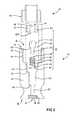
- FIG. 2 shows an exploded view of an embodiment of an injection means 14.
- the illustrated individual components are joined together in the vertical direction. You can see a vertical sectional view of the components.
- the injection means 14 comprises a nozzle housing 24 having a fluid inlet 16 on a first side 46 and a fluid outlet 17 on a second side 49 opposite the first side 46.
- the nozzle housing 24 has a first internal thread 44 on the first side 46.
- the first internal thread 44 defines a connecting piece 25, with which the injection means 14 on a nozzle 26th can be screwed.
- the nozzle 26 has a first external thread 45, which corresponds to the first internal thread 44 of the nozzle housing 24.
- the injector 14 is supplied to a pressurized fluid.
- a second internal thread 50 is formed in the nozzle housing 24 with a smaller thread diameter compared to the first internal thread 44.
- a body 43 with a second, to the second internal thread 44 corresponding external thread 51 can be fastened by screwing.
- the body 43 has a through hole 48 in its center. If the body 43 is fixed in the nozzle housing 24, the through hole 48 forms at its outer end the fluid inlet 16 of the injection means 14 and at its inner end a valve seat 21 as part of a valve device 19th
- valve device 19 With the attachment of the body 43 in the nozzle housing 24, the valve device 19 is simultaneously formed in a first recess 47 of the nozzle housing 24, between a bottom 54 of the first recess 47 and the body 43.
- the valve device 19 comprises a perforated disc 52, a coil spring 22, a valve piston 20, which has a shaft 55 and a front end 56, and the already mentioned valve seat 21.
- the spiral spring 22 has a first side 57, a second side 58 opposite the first side 57 and an interior 59.
- the coil spring 22 is in the tensioned state, ie, the spring is compressed in its longitudinal direction, ie between its first side 57 and its second side 58.
- the coil spring 22 presses with its first side 57 the perforated disk 52 arranged below it against the underside 54 of the first recess 47.
- the valve piston 20 is arranged on the second side 58 of the spiral spring 22.
- the shaft 55 of the valve piston 22 is located completely in the interior 59 of the coil spring, so that the coil spring presses with its second side 58 against a back 63 of the front end 56 of the valve piston 20 and thus presses the front end 56 of the valve piston against the valve seat 21.
- valve seat 21 is thus closed fluid-tight by the front end 56 of the valve piston 20.
- the body 43 is screwed sealingly into the second internal thread 50.
- a second recess 62 of the nozzle housing 24 At the bottom 54 of the first recess 47 is a second recess 62 of the nozzle housing 24, whose diameter is smaller than the diameter of the first recess 47.
- This second recess 62 connects the first recess 47 with the fluid outlet 17, of a nozzle-like constriction 18th is formed.
- the fluid outlet 17 is embedded in a swirl generating device 23.
- an injection means 14 which includes up to a threshold pressure P A1 and opens on reaching or exceeding the threshold pressure P A1, thereby generating a spray.
- the required for opening the injection means Threshold pressure can be varied.
Landscapes
- Chemical & Material Sciences (AREA)
- Engineering & Computer Science (AREA)
- Dispersion Chemistry (AREA)
- Combustion & Propulsion (AREA)
- Mechanical Engineering (AREA)
- General Engineering & Computer Science (AREA)
- Air Humidification (AREA)
- Air Conditioning Control Device (AREA)
- Thermotherapy And Cooling Therapy Devices (AREA)
- Devices For Blowing Cold Air, Devices For Blowing Warm Air, And Means For Preventing Water Condensation In Air Conditioning Units (AREA)
Claims (11)
- Dispositif d'humidification d'air, comprenant au moins une pompe haute pression avec une entrée de pompe (12) et une sortie de pompe (13) et au moins deux groupes (A, B, ...., G) de moyens d'injection (14, 15), dans lequel la pompe haute pression (11) envoie de l'eau aux moyens d'injection (14, 15, 27, ..., 31) en fonction des besoins, en particulier pour l'humidification directe ou indirecte d'une pièce ou à des fins de refroidissement, caractérisé en ce que les moyens d'injection (14, 15, 27, ..., 31) des différents groupes (A, B, ...., G) sont configurés et raccordés de façon à s'ouvrir automatiquement à différents seuils de pression PA1, PB1, ... PG1.
- Dispositif d'humidification d'air selon la revendication 1, caractérisé en ce que les moyens d'injection (14) d'un premier groupe (A) s'ouvrent à un seuil de pression PA1 < 10 bars, en particulier < 1 bar, notamment tout de suite après leur alimentation en eau par la pompe haute pression, tandis que les moyens d'injection (15, 27, ..., 31) d'un deuxième groupe et le cas échéant d'autres groupes (B, ..., G) restent dans un premier temps fermés à PA1.
- Dispositif d'humidification d'air selon la revendication 1 ou la revendication 2, caractérisé en ce que les moyens d'injection (14, 15, 27, ..., 31) à l'état ouvert se ferment lorsque la pression chute à une pression de fermeture PA2, PB2, ... PG2, les moyens d'injection des différents groupes (A, B, ... G) étant configurés et raccordés de telle façon que chaque pression de fermeture PA2, PB2, ... PG2 ne descende pas de plus de 10 bars, de préférence pas de plus de 3 bars, en dessous du seuil de pression PA1, PB1, ... PG1 correspondant.
- Dispositif d'humidification d'air selon l'une des revendications 1 à 3, caractérisé en ce qu'il est prévu de trois à sept groupes (A, B, C, D, E, F, G) de moyens d'injection (14, 15, 27, ..., 31) avec différents seuils de pression (PA1, PB1, ... PG1) et en ce que les moyens d'injection (14, 15, 27, ..., 31) des différents groupes (A, B, ... G) sont configurés et raccordés de telle façon que les seuils de pression (PA1, PB1, ... PG1) des différents groupes diffèrent d'au moins 10 bars, de préférence d'au moins 15 bars.
- Dispositif d'humidification d'air selon l'une des revendications 1 à 4, caractérisé en ce qu'il est prévu de trois à sept groupes (A, B, C, D, E, F, G) de moyens d'injection (14, 15, 27, ..., 31) avec différents seuils de pression (PA1, PB1, ... PG1) et en ce que les moyens d'injection (14, 15, 27, ..., 31) des différents groupes (A, B, ... G) sont configurés et raccordés de telle façon que les seuils de pression (PA1, PB1, ... PG1) augmentent par pas sensiblement égaux.
- Dispositif d'humidification d'air selon l'une des revendications 1 à 5, caractérisé en ce que les moyens d'injection (14, 15, 27, ..., 31) comprennent un agencement de soupape (19) auquel est appliquée une précontrainte définie, avec un piston de soupape (20) et un siège de soupape (21), qui s'ouvre seulement à un seuil de pression (PA1, PB1, ... PG1) prédéterminé et établit ainsi une communication fluide entre l'entrée de fluide (16) et la sortie de fluide (17).
- Dispositif d'humidification d'air selon la revendication 6, caractérisé en ce que l'agencement de soupape (19) auquel est appliquée une précontrainte comprend un ressort, en particulier un ressort spiral (22), qui assure la précontrainte définie.
- Dispositif d'humidification d'air selon l'une des revendications 6 ou 7, caractérisé en ce que le piston de soupape (20) est chargé contre le sens d'écoulement du fluide humidificateur par la précontrainte, en particulier par le ressort ou ressort spiral (22), en direction du siège de soupape (21).
- Dispositif d'humidification d'air selon l'une des revendications 6 à 8, caractérisé en ce qu'un dispositif générateur de giration (23) est disposé entre la sortie de fluide (17) et l'agencement de soupape (19) afin d'imprimer un mouvement giratoire voulu au jet de pulvérisation de fluide humidificateur produit.
- Dispositif d'humidification d'air selon l'une des revendications 6 à 9, caractérisé en ce que la sortie de fluide (17) avec le rétrécissement en forme de buse (18) et l'agencement de soupape (19) sont disposés dans un module commun, en particulier dans un boîtier de buse (24) commun.
- Dispositif d'humidification d'air selon la revendication 10, caractérisé en ce que le module ou le boîtier de buse (24) peut être relié, en particulier vissé, à un corps de buse (26) au moyen d'un raccord (25) qui définit l'entrée de fluide (16).
Priority Applications (4)
| Application Number | Priority Date | Filing Date | Title |
|---|---|---|---|
| DE50306435T DE50306435D1 (de) | 2003-09-05 | 2003-09-05 | Luftbefeuchtungsvorrichtung |
| DE20321005U DE20321005U1 (de) | 2003-09-05 | 2003-09-05 | Luftbefeuchtungsvorrichtung |
| EP03020139A EP1512920B1 (fr) | 2003-09-05 | 2003-09-05 | Dispositif d'humidification d'air |
| AT03020139T ATE353131T1 (de) | 2003-09-05 | 2003-09-05 | Luftbefeuchtungsvorrichtung |
Applications Claiming Priority (1)
| Application Number | Priority Date | Filing Date | Title |
|---|---|---|---|
| EP03020139A EP1512920B1 (fr) | 2003-09-05 | 2003-09-05 | Dispositif d'humidification d'air |
Publications (2)
| Publication Number | Publication Date |
|---|---|
| EP1512920A1 EP1512920A1 (fr) | 2005-03-09 |
| EP1512920B1 true EP1512920B1 (fr) | 2007-01-31 |
Family
ID=34130146
Family Applications (1)
| Application Number | Title | Priority Date | Filing Date |
|---|---|---|---|
| EP03020139A Expired - Lifetime EP1512920B1 (fr) | 2003-09-05 | 2003-09-05 | Dispositif d'humidification d'air |
Country Status (3)
| Country | Link |
|---|---|
| EP (1) | EP1512920B1 (fr) |
| AT (1) | ATE353131T1 (fr) |
| DE (2) | DE50306435D1 (fr) |
Families Citing this family (3)
| Publication number | Priority date | Publication date | Assignee | Title |
|---|---|---|---|---|
| ITPD20060051A1 (it) | 2006-02-21 | 2007-08-22 | Carel Spa | Impianto di umidificazione d'aria per ambienti di grandi dimensioni ed un modulo di umidificazione utilizzabile in detto impianto |
| DE202008013622U1 (de) | 2008-10-14 | 2008-12-18 | Michelbach, Ludwig | Druckgesteuerte Ventildüse |
| DE102016124478A1 (de) * | 2016-12-15 | 2018-06-21 | Eisenmann Se | Vorrichtung zum Befeuchten eines Luftstroms |
Family Cites Families (9)
| Publication number | Priority date | Publication date | Assignee | Title |
|---|---|---|---|---|
| GB774604A (en) * | 1954-11-29 | 1957-05-15 | William Murray | Improvements in and relating to self-actuating valves |
| US2921747A (en) * | 1958-08-14 | 1960-01-19 | Bosch Arma Corp | Nozzle |
| US4830046A (en) * | 1988-04-22 | 1989-05-16 | Hose Specialties/Capri, Inc. | Excess flow control valve |
| US5441202A (en) * | 1994-04-20 | 1995-08-15 | Wintering; Gary F. | Misting system with improved couplers |
| US5765752A (en) * | 1996-01-26 | 1998-06-16 | Dgh Systems, L.L.C. | Airless atomizing nozzle and system for humidity control |
| DE19614446C1 (de) * | 1996-04-12 | 1998-01-29 | Umeta Hermann Ulrichskoetter M | Fettpresse |
| DE19807683C1 (de) * | 1998-02-25 | 1999-09-30 | Ludwig Michelbach | Luftbefeuchtungsvorrichtung |
| DE10105397A1 (de) * | 2001-02-07 | 2002-08-08 | Draabe Industrietechnik Gmbh | Ansteuerung bei Luftbefeuchtern mit Nachverdunster |
| US20030034072A1 (en) * | 2001-08-20 | 2003-02-20 | Bui Quy B. | Valve assembly design |
-
2003
- 2003-09-05 EP EP03020139A patent/EP1512920B1/fr not_active Expired - Lifetime
- 2003-09-05 AT AT03020139T patent/ATE353131T1/de active
- 2003-09-05 DE DE50306435T patent/DE50306435D1/de not_active Expired - Lifetime
- 2003-09-05 DE DE20321005U patent/DE20321005U1/de not_active Expired - Lifetime
Also Published As
| Publication number | Publication date |
|---|---|
| DE50306435D1 (de) | 2007-03-22 |
| DE20321005U1 (de) | 2005-09-15 |
| EP1512920A1 (fr) | 2005-03-09 |
| ATE353131T1 (de) | 2007-02-15 |
Similar Documents
| Publication | Publication Date | Title |
|---|---|---|
| CH699322A1 (de) | Verfahren zum einstellen eines helmholtz-resonators sowie helmholtz-resonator zur durchführung des verfahrens. | |
| DE2752938A1 (de) | Steuerventilanordnung fuer zahnaerztliche geraete | |
| EP1243343A1 (fr) | Buse de vaporisation à deux fluides | |
| DE10123775A1 (de) | Kraftstoff-Einspritzvorrichtung für Brennkraftmaschinen, insbesondere Common-Rail-Injektor, sowie Kraftstoffsystem und Brennkraftmaschine | |
| AT503660B1 (de) | Vorrichtung zum einspritzen von kraftstoff in den brennraum einer brennkraftmaschine | |
| EP1319357A2 (fr) | Dispositif de production de mousse dans le filtre d'une machine de café-espresso | |
| DE2453734B2 (fr) | ||
| DE202008017846U1 (de) | Trennmittelsprühvorrichtung für eine Gießmaschine | |
| DE10250532B3 (de) | Treibgas betriebene Ejektoranordnung | |
| EP1213485A2 (fr) | Dispositif pour l'obtention d'un vide et procédé d'opération du dispositif | |
| EP1512920B1 (fr) | Dispositif d'humidification d'air | |
| EP0731315B1 (fr) | Soupape de fermeture pour une buse et buse de pulvérisation sous pression avec une telle soupape de fermeture | |
| EP2415533B1 (fr) | Agencement de nettoyage destiné au nettoyage des installations de traitement de récipients | |
| DE69722419T2 (de) | Verfahren und vorrichtung zur kontrolle des einspritzdrucks von flüssigem brennstoff | |
| EP0289712A2 (fr) | Régulateur de pression | |
| DE102021133674A1 (de) | Düse mit einstellbarer Strahlgeometrie, Düsenanordnung und Verfahren zum Betrieb einer Düse | |
| DE102004062008A1 (de) | Kraftstofffilter mit Auslassöffnungen, die vorzugsweise mit einem hydroerosiven Verfahren bearbeitet sind | |
| DE4330651C2 (de) | Zusatzeinrichtung für eine Wasserentnahmestelle | |
| DE2825983A1 (de) | Vorrichtung (mischkopf) zum erzeugen eines reaktionsfaehigen gemisches aus mindestens zwei kunststoffkomponenten | |
| EP0806246A1 (fr) | Vanne d'arrêt pour buse et buse de pulvérisation par pression munie d'une telle vanne | |
| DE3820350A1 (de) | Vorrichtung zur umwaelzung von wasser bei sanitaereinbauten | |
| DE2820335A1 (de) | Spruehdose fuer eine brausebadvorrichtung | |
| DE4010134A1 (de) | Luftzufuehrungsvorrichtung fuer die raumklimatisierung | |
| DE3533363C1 (de) | Sicherheitsueberstroemventil | |
| DE20210016U1 (de) | Druckluft-Wartungsvorrichtung |
Legal Events
| Date | Code | Title | Description |
|---|---|---|---|
| PUAI | Public reference made under article 153(3) epc to a published international application that has entered the european phase |
Free format text: ORIGINAL CODE: 0009012 |
|
| AK | Designated contracting states |
Kind code of ref document: A1 Designated state(s): AT BE BG CH CY CZ DE DK EE ES FI FR GB GR HU IE IT LI LU MC NL PT RO SE SI SK TR |
|
| AX | Request for extension of the european patent |
Extension state: AL LT LV MK |
|
| 17P | Request for examination filed |
Effective date: 20050729 |
|
| AKX | Designation fees paid |
Designated state(s): AT BE BG CH CY CZ DE DK EE ES FI FR GB GR HU IE IT LI LU MC NL PT RO SE SI SK TR |
|
| GRAP | Despatch of communication of intention to grant a patent |
Free format text: ORIGINAL CODE: EPIDOSNIGR1 |
|
| GRAS | Grant fee paid |
Free format text: ORIGINAL CODE: EPIDOSNIGR3 |
|
| GRAA | (expected) grant |
Free format text: ORIGINAL CODE: 0009210 |
|
| AK | Designated contracting states |
Kind code of ref document: B1 Designated state(s): AT BE BG CH CY CZ DE DK EE ES FI FR GB GR HU IE IT LI LU MC NL PT RO SE SI SK TR |
|
| PG25 | Lapsed in a contracting state [announced via postgrant information from national office to epo] |
Ref country code: IE Free format text: LAPSE BECAUSE OF FAILURE TO SUBMIT A TRANSLATION OF THE DESCRIPTION OR TO PAY THE FEE WITHIN THE PRESCRIBED TIME-LIMIT Effective date: 20070131 Ref country code: NL Free format text: LAPSE BECAUSE OF FAILURE TO SUBMIT A TRANSLATION OF THE DESCRIPTION OR TO PAY THE FEE WITHIN THE PRESCRIBED TIME-LIMIT Effective date: 20070131 Ref country code: DK Free format text: LAPSE BECAUSE OF FAILURE TO SUBMIT A TRANSLATION OF THE DESCRIPTION OR TO PAY THE FEE WITHIN THE PRESCRIBED TIME-LIMIT Effective date: 20070131 Ref country code: SI Free format text: LAPSE BECAUSE OF FAILURE TO SUBMIT A TRANSLATION OF THE DESCRIPTION OR TO PAY THE FEE WITHIN THE PRESCRIBED TIME-LIMIT Effective date: 20070131 Ref country code: FI Free format text: LAPSE BECAUSE OF FAILURE TO SUBMIT A TRANSLATION OF THE DESCRIPTION OR TO PAY THE FEE WITHIN THE PRESCRIBED TIME-LIMIT Effective date: 20070131 |
|
| REG | Reference to a national code |
Ref country code: GB Ref legal event code: FG4D Free format text: NOT ENGLISH |
|
| REG | Reference to a national code |
Ref country code: CH Ref legal event code: EP |
|
| REG | Reference to a national code |
Ref country code: IE Ref legal event code: FG4D Free format text: LANGUAGE OF EP DOCUMENT: GERMAN |
|
| REF | Corresponds to: |
Ref document number: 50306435 Country of ref document: DE Date of ref document: 20070322 Kind code of ref document: P |
|
| PG25 | Lapsed in a contracting state [announced via postgrant information from national office to epo] |
Ref country code: SE Free format text: LAPSE BECAUSE OF FAILURE TO SUBMIT A TRANSLATION OF THE DESCRIPTION OR TO PAY THE FEE WITHIN THE PRESCRIBED TIME-LIMIT Effective date: 20070430 |
|
| PG25 | Lapsed in a contracting state [announced via postgrant information from national office to epo] |
Ref country code: BG Free format text: LAPSE BECAUSE OF EXPIRATION OF PROTECTION Effective date: 20070501 |
|
| PG25 | Lapsed in a contracting state [announced via postgrant information from national office to epo] |
Ref country code: ES Free format text: LAPSE BECAUSE OF FAILURE TO SUBMIT A TRANSLATION OF THE DESCRIPTION OR TO PAY THE FEE WITHIN THE PRESCRIBED TIME-LIMIT Effective date: 20070512 |
|
| PG25 | Lapsed in a contracting state [announced via postgrant information from national office to epo] |
Ref country code: PT Free format text: LAPSE BECAUSE OF FAILURE TO SUBMIT A TRANSLATION OF THE DESCRIPTION OR TO PAY THE FEE WITHIN THE PRESCRIBED TIME-LIMIT Effective date: 20070702 |
|
| NLV1 | Nl: lapsed or annulled due to failure to fulfill the requirements of art. 29p and 29m of the patents act | ||
| GBV | Gb: ep patent (uk) treated as always having been void in accordance with gb section 77(7)/1977 [no translation filed] |
Effective date: 20070131 |
|
| REG | Reference to a national code |
Ref country code: IE Ref legal event code: FD4D |
|
| EN | Fr: translation not filed | ||
| PG25 | Lapsed in a contracting state [announced via postgrant information from national office to epo] |
Ref country code: SK Free format text: LAPSE BECAUSE OF FAILURE TO SUBMIT A TRANSLATION OF THE DESCRIPTION OR TO PAY THE FEE WITHIN THE PRESCRIBED TIME-LIMIT Effective date: 20070131 Ref country code: GB Free format text: LAPSE BECAUSE OF FAILURE TO SUBMIT A TRANSLATION OF THE DESCRIPTION OR TO PAY THE FEE WITHIN THE PRESCRIBED TIME-LIMIT Effective date: 20070131 |
|
| PLBE | No opposition filed within time limit |
Free format text: ORIGINAL CODE: 0009261 |
|
| STAA | Information on the status of an ep patent application or granted ep patent |
Free format text: STATUS: NO OPPOSITION FILED WITHIN TIME LIMIT |
|
| PG25 | Lapsed in a contracting state [announced via postgrant information from national office to epo] |
Ref country code: CZ Free format text: LAPSE BECAUSE OF FAILURE TO SUBMIT A TRANSLATION OF THE DESCRIPTION OR TO PAY THE FEE WITHIN THE PRESCRIBED TIME-LIMIT Effective date: 20070131 Ref country code: RO Free format text: LAPSE BECAUSE OF FAILURE TO SUBMIT A TRANSLATION OF THE DESCRIPTION OR TO PAY THE FEE WITHIN THE PRESCRIBED TIME-LIMIT Effective date: 20070131 |
|
| 26N | No opposition filed |
Effective date: 20071101 |
|
| BERE | Be: lapsed |
Owner name: MICHELBACH, LUDWIG Effective date: 20070930 |
|
| PG25 | Lapsed in a contracting state [announced via postgrant information from national office to epo] |
Ref country code: GR Free format text: LAPSE BECAUSE OF FAILURE TO SUBMIT A TRANSLATION OF THE DESCRIPTION OR TO PAY THE FEE WITHIN THE PRESCRIBED TIME-LIMIT Effective date: 20070501 Ref country code: FR Free format text: LAPSE BECAUSE OF FAILURE TO SUBMIT A TRANSLATION OF THE DESCRIPTION OR TO PAY THE FEE WITHIN THE PRESCRIBED TIME-LIMIT Effective date: 20070921 Ref country code: IT Free format text: LAPSE BECAUSE OF FAILURE TO SUBMIT A TRANSLATION OF THE DESCRIPTION OR TO PAY THE FEE WITHIN THE PRESCRIBED TIME-LIMIT Effective date: 20070131 Ref country code: MC Free format text: LAPSE BECAUSE OF NON-PAYMENT OF DUE FEES Effective date: 20070930 |
|
| PG25 | Lapsed in a contracting state [announced via postgrant information from national office to epo] |
Ref country code: BE Free format text: LAPSE BECAUSE OF NON-PAYMENT OF DUE FEES Effective date: 20070930 |
|
| PG25 | Lapsed in a contracting state [announced via postgrant information from national office to epo] |
Ref country code: FR Free format text: LAPSE BECAUSE OF FAILURE TO SUBMIT A TRANSLATION OF THE DESCRIPTION OR TO PAY THE FEE WITHIN THE PRESCRIBED TIME-LIMIT Effective date: 20070131 |
|
| PG25 | Lapsed in a contracting state [announced via postgrant information from national office to epo] |
Ref country code: EE Free format text: LAPSE BECAUSE OF FAILURE TO SUBMIT A TRANSLATION OF THE DESCRIPTION OR TO PAY THE FEE WITHIN THE PRESCRIBED TIME-LIMIT Effective date: 20070131 |
|
| REG | Reference to a national code |
Ref country code: CH Ref legal event code: NV Representative=s name: CAVID GMBH |
|
| PG25 | Lapsed in a contracting state [announced via postgrant information from national office to epo] |
Ref country code: CY Free format text: LAPSE BECAUSE OF FAILURE TO SUBMIT A TRANSLATION OF THE DESCRIPTION OR TO PAY THE FEE WITHIN THE PRESCRIBED TIME-LIMIT Effective date: 20070131 |
|
| PG25 | Lapsed in a contracting state [announced via postgrant information from national office to epo] |
Ref country code: LU Free format text: LAPSE BECAUSE OF NON-PAYMENT OF DUE FEES Effective date: 20070905 |
|
| PG25 | Lapsed in a contracting state [announced via postgrant information from national office to epo] |
Ref country code: HU Free format text: LAPSE BECAUSE OF FAILURE TO SUBMIT A TRANSLATION OF THE DESCRIPTION OR TO PAY THE FEE WITHIN THE PRESCRIBED TIME-LIMIT Effective date: 20070801 Ref country code: TR Free format text: LAPSE BECAUSE OF FAILURE TO SUBMIT A TRANSLATION OF THE DESCRIPTION OR TO PAY THE FEE WITHIN THE PRESCRIBED TIME-LIMIT Effective date: 20070131 |
|
| REG | Reference to a national code |
Ref country code: CH Ref legal event code: NV Representative=s name: REUTELER & CIE S.A. |
|
| PGFP | Annual fee paid to national office [announced via postgrant information from national office to epo] |
Ref country code: CH Payment date: 20150925 Year of fee payment: 13 |
|
| PGFP | Annual fee paid to national office [announced via postgrant information from national office to epo] |
Ref country code: AT Payment date: 20150929 Year of fee payment: 13 |
|
| PGFP | Annual fee paid to national office [announced via postgrant information from national office to epo] |
Ref country code: DE Payment date: 20151127 Year of fee payment: 13 |
|
| REG | Reference to a national code |
Ref country code: DE Ref legal event code: R119 Ref document number: 50306435 Country of ref document: DE |
|
| REG | Reference to a national code |
Ref country code: CH Ref legal event code: PL |
|
| REG | Reference to a national code |
Ref country code: AT Ref legal event code: MM01 Ref document number: 353131 Country of ref document: AT Kind code of ref document: T Effective date: 20160905 |
|
| PG25 | Lapsed in a contracting state [announced via postgrant information from national office to epo] |
Ref country code: LI Free format text: LAPSE BECAUSE OF NON-PAYMENT OF DUE FEES Effective date: 20160930 Ref country code: CH Free format text: LAPSE BECAUSE OF NON-PAYMENT OF DUE FEES Effective date: 20160930 Ref country code: DE Free format text: LAPSE BECAUSE OF NON-PAYMENT OF DUE FEES Effective date: 20170401 |
|
| PG25 | Lapsed in a contracting state [announced via postgrant information from national office to epo] |
Ref country code: AT Free format text: LAPSE BECAUSE OF NON-PAYMENT OF DUE FEES Effective date: 20160905 |