EP1514758A1 - Dispositif de raccordement d' un étrier de frein et une pompe pour des freins hydrauliques - Google Patents
Dispositif de raccordement d' un étrier de frein et une pompe pour des freins hydrauliques Download PDFInfo
- Publication number
- EP1514758A1 EP1514758A1 EP20040425659 EP04425659A EP1514758A1 EP 1514758 A1 EP1514758 A1 EP 1514758A1 EP 20040425659 EP20040425659 EP 20040425659 EP 04425659 A EP04425659 A EP 04425659A EP 1514758 A1 EP1514758 A1 EP 1514758A1
- Authority
- EP
- European Patent Office
- Prior art keywords
- caliper
- pump
- elastic member
- hose
- ports
- Prior art date
- Legal status (The legal status is an assumption and is not a legal conclusion. Google has not performed a legal analysis and makes no representation as to the accuracy of the status listed.)
- Withdrawn
Links
- 230000008878 coupling Effects 0.000 claims abstract description 11
- 238000010168 coupling process Methods 0.000 claims abstract description 11
- 238000005859 coupling reaction Methods 0.000 claims abstract description 11
- 239000012530 fluid Substances 0.000 claims abstract description 6
- 230000002441 reversible effect Effects 0.000 claims abstract description 4
- 230000001747 exhibiting effect Effects 0.000 claims description 2
- 238000012423 maintenance Methods 0.000 description 2
- 230000001419 dependent effect Effects 0.000 description 1
- 230000002035 prolonged effect Effects 0.000 description 1
Images


Classifications
-
- F—MECHANICAL ENGINEERING; LIGHTING; HEATING; WEAPONS; BLASTING
- F16—ENGINEERING ELEMENTS AND UNITS; GENERAL MEASURES FOR PRODUCING AND MAINTAINING EFFECTIVE FUNCTIONING OF MACHINES OR INSTALLATIONS; THERMAL INSULATION IN GENERAL
- F16L—PIPES; JOINTS OR FITTINGS FOR PIPES; SUPPORTS FOR PIPES, CABLES OR PROTECTIVE TUBING; MEANS FOR THERMAL INSULATION IN GENERAL
- F16L37/00—Couplings of the quick-acting type
- F16L37/28—Couplings of the quick-acting type with fluid cut-off means
- F16L37/30—Couplings of the quick-acting type with fluid cut-off means with fluid cut-off means in each of two pipe-end fittings
- F16L37/32—Couplings of the quick-acting type with fluid cut-off means with fluid cut-off means in each of two pipe-end fittings at least one of two lift valves being opened automatically when the coupling is applied
- F16L37/35—Couplings of the quick-acting type with fluid cut-off means with fluid cut-off means in each of two pipe-end fittings at least one of two lift valves being opened automatically when the coupling is applied at least one of the valves having an axial bore communicating with lateral apertures
-
- B—PERFORMING OPERATIONS; TRANSPORTING
- B60—VEHICLES IN GENERAL
- B60T—VEHICLE BRAKE CONTROL SYSTEMS OR PARTS THEREOF; BRAKE CONTROL SYSTEMS OR PARTS THEREOF, IN GENERAL; ARRANGEMENT OF BRAKING ELEMENTS ON VEHICLES IN GENERAL; PORTABLE DEVICES FOR PREVENTING UNWANTED MOVEMENT OF VEHICLES; VEHICLE MODIFICATIONS TO FACILITATE COOLING OF BRAKES
- B60T17/00—Component parts, details, or accessories of power brake systems not covered by groups B60T8/00, B60T13/00 or B60T15/00, or presenting other characteristic features
- B60T17/04—Arrangements of piping, valves in the piping, e.g. cut-off valves, couplings or air hoses
- B60T17/043—Brake line couplings, air hoses and stopcocks
-
- Y—GENERAL TAGGING OF NEW TECHNOLOGICAL DEVELOPMENTS; GENERAL TAGGING OF CROSS-SECTIONAL TECHNOLOGIES SPANNING OVER SEVERAL SECTIONS OF THE IPC; TECHNICAL SUBJECTS COVERED BY FORMER USPC CROSS-REFERENCE ART COLLECTIONS [XRACs] AND DIGESTS
- Y10—TECHNICAL SUBJECTS COVERED BY FORMER USPC
- Y10T—TECHNICAL SUBJECTS COVERED BY FORMER US CLASSIFICATION
- Y10T137/00—Fluid handling
- Y10T137/8593—Systems
- Y10T137/87917—Flow path with serial valves and/or closures
- Y10T137/87925—Separable flow path section, valve or closure in each
- Y10T137/87941—Each valve and/or closure operated by coupling motion
- Y10T137/87949—Linear motion of flow path sections operates both
- Y10T137/87957—Valves actuate each other
Definitions
- the present invention relates to an apparatus for connection of a caliper and a pump for hydraulic brakes.
- connection between a caliper and a pump of a hydraulic brake is known to be made up of a hose acting as a means for transmitting the braking-activation command from the pump to the caliper. It is also known that, in case of novel assembly of the braking system on a vehicle, either for maintenance or replacement of a component of the system, a draining operation is performed to ensure that no air bubbles are present in the circuit of the hydraulic fluid which are likely to cause drawbacks when the system is started. Accordingly, every time a system's assembly or service operation is carried out, or a component is replaced, such operation takes a relatively long time and is to be entrusted to qualified personnel, so that the incidence of the cost of labour is cause for a rise in the cost of the whole operation.
- the main object of the present invention is to eliminate, or at least greatly reduce, the above drawbacks.
- the present invention makes it possible to drastically reduce the times for assembly or for maintenance of braking systems of the type above mentioned, by eliminating the need of providing each time for a drainage of the system and, at the same time, ensuring a higher efficiency in storing, handling and transporting the individual components.
- an apparatus according to the present invention is relatively easy to make, cost-effective and reliable even after a prolonged service life.
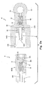
- an apparatus comprises a hose (1), preferably flexible, able to be filled with fluid for hydraulic brakes and provided, in correspondence of both ends, with a hermetic-seal reversible coupling (2) to allow a tight-seal, reversible connection, on one side, with a body (4) connecting with a pump for hydraulic brakes and, on the other side, with a body (5) connecting with a caliper of a hydraulic brake.
- a hose (1) preferably flexible, able to be filled with fluid for hydraulic brakes and provided, in correspondence of both ends, with a hermetic-seal reversible coupling (2) to allow a tight-seal, reversible connection, on one side, with a body (4) connecting with a pump for hydraulic brakes and, on the other side, with a body (5) connecting with a caliper of a hydraulic brake.
- each coupling (2) located at both ends of hose (1) are identical with each other and, structurally identical to each other are also the said connectors (4) and (5).
- each coupling (2) comprises a substantially cylindrical body (6) which has a drilled shank (60) to be fitted into the hose (1) and is located inside a ring nut (7) having internal threading and whose inner diameter (dg) is larger than the outer diameter (dc) of the cylindrical body (6), so that a cylindrical space (3) results between the body (6) and the ring nut (7).
- a spring (8) disposed along the longitudinal axis of body (6) and to which a piston (9) is associated.
- the body of the latter has a substantially spherical shape, with a rear appendix (92) on which an end portion of said spring (8) is fitted, and with four radial appendixes (91) which, in cooperation with the internal wall of said body (6), define four ports (90).
- the said appendixes (91) of the piston (9) are orthogonal to the longitudinal axis of the cylinder (6), and the said ports (90) are parallel to said axis; the spring (8) results between the piston (9) and the base (61) of cylinder (6) from which the shank (60) extends to fit into the hose (1).
- a collar (10) Mounted in correspondence of the other base (62) of cylinder (6) is a collar (10) and, between the latter and the piston (9) there is interposed a multilobe O-ring (101).
- the said collar (10) and the said O-ring (101) are disposed coaxial to each other and inside the cylinder (6).
- the inner diameter of the O-ring (101) is smaller than that of the piston with spherical head (9), so that the same piston results suitable for closing the port thereof.
- the piston with spherical head (9) results between the spring (8) and the O-ring (101) which, in turn, results between the piston with spherical head (9) and the collar (10).
- each of said connectors (4, 5) comprises a body (11) exhibiting an internal cavity which communicates, through a corresponding port (12, 13), with a pump or respectively with a caliper of the braking system.
- the said body (11) has a front portion (14) with external threading on which a ring nut (7) of a coupling (2) is to be screwed and whose inner diameter (da) is equal to the internal diameter (dg) of the ring nut (7), so that the cavity (140) delimited by said portion (14) of body (11) will result suitable for receiving the portion of body (6) which results inside the ring nut (7).
- the length (Ia) of said portion (14) of body (11) is such that when screwing the ring nut (7) all the way in onto the threaded portion (14) of body (11), the front base (62) of body (6) belonging to the coupling (2) will result in abutment with an internal base (141) of the said cavity (140).
- a hollow pin (15) associated with a spring (16) positioned between the rear base of the same pin (15) and the said port (12), that is, positioned within a second cavity (17) of body (11) and communicating with the first cavity (140) coaxially thereto.
- the said pin (15) exhibits a front port (150) and a perimetral rear port (151), and can slide freely within the ports of a collar (18) and a multilobe O-ring (19) fitted on the same pin on the back of said internal base (141).
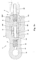
- the operational and constructional structure is substantially equal to that of the example shown in Figs. 1A-1E, except that the bodies (6) and (11) are not provided with threading and their mutual attachment is carried out by screw means acting through a hole (110) formed in the body (11) of connector (4, 5) and interesting the internal surface of the body (6) of each coupling (2) in correspondence of an annular groove (600).
Landscapes
- Engineering & Computer Science (AREA)
- Mechanical Engineering (AREA)
- General Engineering & Computer Science (AREA)
- Transportation (AREA)
- Valves And Accessory Devices For Braking Systems (AREA)
- Braking Arrangements (AREA)
Applications Claiming Priority (2)
| Application Number | Priority Date | Filing Date | Title |
|---|---|---|---|
| ITFI20030240 | 2003-09-12 | ||
| ITFI20030240 ITFI20030240A1 (it) | 2003-09-12 | 2003-09-12 | Dispositivo per il collegamento di una pinza e di una pompa per freni idraulici |
Publications (1)
| Publication Number | Publication Date |
|---|---|
| EP1514758A1 true EP1514758A1 (fr) | 2005-03-16 |
Family
ID=34131185
Family Applications (1)
| Application Number | Title | Priority Date | Filing Date |
|---|---|---|---|
| EP20040425659 Withdrawn EP1514758A1 (fr) | 2003-09-12 | 2004-09-01 | Dispositif de raccordement d' un étrier de frein et une pompe pour des freins hydrauliques |
Country Status (3)
| Country | Link |
|---|---|
| US (1) | US20050056325A1 (fr) |
| EP (1) | EP1514758A1 (fr) |
| IT (1) | ITFI20030240A1 (fr) |
Cited By (5)
| Publication number | Priority date | Publication date | Assignee | Title |
|---|---|---|---|---|
| EP2410197A1 (fr) * | 2010-07-20 | 2012-01-25 | Hansen Industrial Transmissions | Système de freinage pour boîte de vitesse industrielle |
| US9827968B2 (en) | 2015-01-12 | 2017-11-28 | Sram, Llc | Hydraulic bicycle system |
| WO2019081247A1 (fr) * | 2017-10-25 | 2019-05-02 | Continental Teves Ag & Co. Ohg | Réservoir de fluide muni d'une valve de coupure |
| EP3756961A2 (fr) | 2019-06-03 | 2020-12-30 | Gustav Magenwirth GmbH & Co. KG | Accouplement de conduite hydraulique, en particulier pour un frein ou embrayage hydraulique d'un véhicule dirigé par guidon |
| WO2022137160A1 (fr) * | 2020-12-22 | 2022-06-30 | Danfoss Power Solutions Ii Technology A/S | Coupleur de fluide de frein sécurisé |
Families Citing this family (2)
| Publication number | Priority date | Publication date | Assignee | Title |
|---|---|---|---|---|
| JP2008084809A (ja) * | 2006-08-29 | 2008-04-10 | Yamaha Motor Co Ltd | 水素供給用配管の接続構造 |
| ITMI20130522A1 (it) * | 2013-04-05 | 2014-10-06 | Alfa Gomma S P A | Innesto rapido idraulico o oleodimamico per fluido in pressione |
Citations (6)
| Publication number | Priority date | Publication date | Assignee | Title |
|---|---|---|---|---|
| US2108714A (en) * | 1935-09-28 | 1938-02-15 | Hirsch Peter | Pipe coupling |
| DE953856C (de) * | 1953-07-01 | 1956-12-06 | Vogel Willy Fa | Steck- und Abreisskupplung fuer Verbindungsleitungen, insbesondere zwischen Fahrzeugen |
| GB870822A (en) * | 1958-10-20 | 1961-06-21 | Spembly Ltd | Improvements in or relating to pipe line couplings |
| GB968522A (en) * | 1960-01-22 | 1964-09-02 | Plessey Co Ltd | Improvements in or relating to mounting arrangements including fluid couplings |
| JPH03153991A (ja) * | 1989-11-10 | 1991-07-01 | Hitachi Cable Ltd | ブレーキホース |
| JPH10220671A (ja) * | 1997-02-07 | 1998-08-21 | Aisan Ind Co Ltd | 管継手 |
Family Cites Families (3)
| Publication number | Priority date | Publication date | Assignee | Title |
|---|---|---|---|---|
| US4624291A (en) * | 1984-04-30 | 1986-11-25 | Automotive Products Plc | Method of prefilling modular hydraulic control apparatus |
| US4607670A (en) * | 1983-11-28 | 1986-08-26 | Automotive Products Plc | Modular prefilled hydraulic control apparatus |
| FR2614371B1 (fr) * | 1987-04-23 | 1993-04-09 | Bennes Marrel | Valve de commande, notamment pour les freins hydrauliques d'un vehicule |
-
2003
- 2003-09-12 IT ITFI20030240 patent/ITFI20030240A1/it unknown
-
2004
- 2004-08-24 US US10/925,266 patent/US20050056325A1/en not_active Abandoned
- 2004-09-01 EP EP20040425659 patent/EP1514758A1/fr not_active Withdrawn
Patent Citations (6)
| Publication number | Priority date | Publication date | Assignee | Title |
|---|---|---|---|---|
| US2108714A (en) * | 1935-09-28 | 1938-02-15 | Hirsch Peter | Pipe coupling |
| DE953856C (de) * | 1953-07-01 | 1956-12-06 | Vogel Willy Fa | Steck- und Abreisskupplung fuer Verbindungsleitungen, insbesondere zwischen Fahrzeugen |
| GB870822A (en) * | 1958-10-20 | 1961-06-21 | Spembly Ltd | Improvements in or relating to pipe line couplings |
| GB968522A (en) * | 1960-01-22 | 1964-09-02 | Plessey Co Ltd | Improvements in or relating to mounting arrangements including fluid couplings |
| JPH03153991A (ja) * | 1989-11-10 | 1991-07-01 | Hitachi Cable Ltd | ブレーキホース |
| JPH10220671A (ja) * | 1997-02-07 | 1998-08-21 | Aisan Ind Co Ltd | 管継手 |
Non-Patent Citations (3)
| Title |
|---|
| ALFRED TEVES GMBH: "Bremsen-Handbuch Berechnung, Funktion, Wartung und Instandsetzung", 1988, AUTOHAUS VERLAG GMBH, OTTOBRUNN, XP002308211 * |
| PATENT ABSTRACTS OF JAPAN vol. 015, no. 381 (M - 1162) 26 September 1991 (1991-09-26) * |
| PATENT ABSTRACTS OF JAPAN vol. 1998, no. 13 30 November 1998 (1998-11-30) * |
Cited By (13)
| Publication number | Priority date | Publication date | Assignee | Title |
|---|---|---|---|---|
| WO2012010586A1 (fr) * | 2010-07-20 | 2012-01-26 | Hansen Industrial Transmissions | Système de frein pour boîte de vitesse industrielle |
| EP2410197A1 (fr) * | 2010-07-20 | 2012-01-25 | Hansen Industrial Transmissions | Système de freinage pour boîte de vitesse industrielle |
| US10407043B2 (en) | 2015-01-12 | 2019-09-10 | Sram, Llc | Hydraulic bicycle system |
| US9827968B2 (en) | 2015-01-12 | 2017-11-28 | Sram, Llc | Hydraulic bicycle system |
| US10086813B2 (en) | 2015-01-12 | 2018-10-02 | Sram, Llc | Hydraulic bicycle system |
| US11590948B2 (en) | 2017-10-25 | 2023-02-28 | Continental Teves Ag & Co. Ohg | Fluid reservoir with a stop valve |
| WO2019081247A1 (fr) * | 2017-10-25 | 2019-05-02 | Continental Teves Ag & Co. Ohg | Réservoir de fluide muni d'une valve de coupure |
| EP3756961A2 (fr) | 2019-06-03 | 2020-12-30 | Gustav Magenwirth GmbH & Co. KG | Accouplement de conduite hydraulique, en particulier pour un frein ou embrayage hydraulique d'un véhicule dirigé par guidon |
| EP3756961A3 (fr) * | 2019-06-03 | 2021-04-28 | Gustav Magenwirth GmbH & Co. KG | Accouplement de conduite hydraulique, en particulier pour un frein ou embrayage hydraulique d'un véhicule dirigé par guidon |
| US11802644B2 (en) | 2019-06-03 | 2023-10-31 | Gustav Magenwirth Gmbh & Co. Kg | Hydraulic line coupling for a hydraulic brake or clutch of handlebar-operated vehicles and hydraulic brake of a handlebar-operated vehicle |
| EP4407224A2 (fr) | 2019-06-03 | 2024-07-31 | Gustav Magenwirth GmbH & Co. KG | Accouplement de conduite hydraulique, en particulier pour un frein ou embrayage hydraulique d'un véhicule dirigé par guidon |
| EP4407224A3 (fr) * | 2019-06-03 | 2024-08-07 | Gustav Magenwirth GmbH & Co. KG | Accouplement de conduite hydraulique, en particulier pour un frein ou embrayage hydraulique d'un véhicule dirigé par guidon |
| WO2022137160A1 (fr) * | 2020-12-22 | 2022-06-30 | Danfoss Power Solutions Ii Technology A/S | Coupleur de fluide de frein sécurisé |
Also Published As
| Publication number | Publication date |
|---|---|
| ITFI20030240A1 (it) | 2005-03-13 |
| US20050056325A1 (en) | 2005-03-17 |
Similar Documents
| Publication | Publication Date | Title |
|---|---|---|
| EP0513296B1 (fr) | Dispositif de montage ou de demontage de sondes situees dans des tuyaux et des reservoirs de traitement | |
| US4211150A (en) | Air cylinder | |
| CN206682153U (zh) | 联动锁紧球关节万向杆 | |
| EP1514758A1 (fr) | Dispositif de raccordement d' un étrier de frein et une pompe pour des freins hydrauliques | |
| BR112012027010B1 (pt) | grupo atuador eletro-hidráulico para uma transmissão mecânica servo assistida automotiva e transmissão mecânica servo assistida automotiva | |
| CN110576414B (zh) | 一种密封圈套接装置及其组装设备 | |
| CN109442194A (zh) | 一种润滑分配器监控系统 | |
| US2557498A (en) | Swing joint | |
| CN208474224U (zh) | 一种液压转换阀 | |
| EP2312169A1 (fr) | Soupape permettant de contrôler le débit d'huile dans un cylindre à simple effet | |
| US7543824B2 (en) | Hydraulic suspension unit | |
| US11300200B2 (en) | Hydraulic control unit with externally mounted pump | |
| JPH0248761B2 (fr) | ||
| CN201082710Y (zh) | 一种制动主缸 | |
| CN100523522C (zh) | 一种万向液压联结器 | |
| CN105826739B (zh) | 用于自动变速器下线测试台的连接插件 | |
| CN104763708B (zh) | 一种污染指示器 | |
| CN112303063A (zh) | 用于旋入式过滤器的适配器插头 | |
| CN114837590B (zh) | 电缆测井牵引器液压推靠短节 | |
| CN207212812U (zh) | 一体式多缸同步液压油缸 | |
| CN106956671B (zh) | 一种手动双阀芯制动阀 | |
| CN211429965U (zh) | 提升器 | |
| CN110285310A (zh) | 一种液压自动切换装置 | |
| CN224106503U (zh) | 一种集成有内部油路的快换接头 | |
| CN213654783U (zh) | 干式柔性短节 |
Legal Events
| Date | Code | Title | Description |
|---|---|---|---|
| PUAI | Public reference made under article 153(3) epc to a published international application that has entered the european phase |
Free format text: ORIGINAL CODE: 0009012 |
|
| AK | Designated contracting states |
Kind code of ref document: A1 Designated state(s): AT BE BG CH CY CZ DE DK EE ES FI FR GB GR HU IE IT LI LU MC NL PL PT RO SE SI SK TR |
|
| AX | Request for extension of the european patent |
Extension state: AL HR LT LV MK |
|
| 17P | Request for examination filed |
Effective date: 20050325 |
|
| AKX | Designation fees paid |
Designated state(s): AT BE BG CH CY CZ DE DK EE ES FI FR GB GR HU IE IT LI LU MC NL PL PT RO SE SI SK TR |
|
| 17Q | First examination report despatched |
Effective date: 20060626 |
|
| STAA | Information on the status of an ep patent application or granted ep patent |
Free format text: STATUS: THE APPLICATION IS DEEMED TO BE WITHDRAWN |
|
| 18D | Application deemed to be withdrawn |
Effective date: 20061107 |