EP1518491A1 - Adapter zum Verbinden einer Kamera mit einem medizinischen Gerät - Google Patents
Adapter zum Verbinden einer Kamera mit einem medizinischen Gerät Download PDFInfo
- Publication number
- EP1518491A1 EP1518491A1 EP04022733A EP04022733A EP1518491A1 EP 1518491 A1 EP1518491 A1 EP 1518491A1 EP 04022733 A EP04022733 A EP 04022733A EP 04022733 A EP04022733 A EP 04022733A EP 1518491 A1 EP1518491 A1 EP 1518491A1
- Authority
- EP
- European Patent Office
- Prior art keywords
- base plate
- tongues
- annular sleeve
- flange
- adapter
- Prior art date
- Legal status (The legal status is an assumption and is not a legal conclusion. Google has not performed a legal analysis and makes no representation as to the accuracy of the status listed.)
- Granted
Links
Images


Classifications
-
- G—PHYSICS
- G02—OPTICS
- G02B—OPTICAL ELEMENTS, SYSTEMS OR APPARATUS
- G02B23/00—Telescopes, e.g. binoculars; Periscopes; Instruments for viewing the inside of hollow bodies; Viewfinders; Optical aiming or sighting devices
- G02B23/24—Instruments or systems for viewing the inside of hollow bodies, e.g. fibrescopes
- G02B23/2476—Non-optical details, e.g. housings, mountings, supports
- G02B23/2484—Arrangements in relation to a camera or imaging device
-
- A—HUMAN NECESSITIES
- A61—MEDICAL OR VETERINARY SCIENCE; HYGIENE
- A61B—DIAGNOSIS; SURGERY; IDENTIFICATION
- A61B1/00—Instruments for performing medical examinations of the interior of cavities or tubes of the body by visual or photographical inspection, e.g. endoscopes; Illuminating arrangements therefor
- A61B1/00112—Connection or coupling means
- A61B1/00121—Connectors, fasteners and adapters, e.g. on the endoscope handle
- A61B1/00126—Connectors, fasteners and adapters, e.g. on the endoscope handle optical, e.g. for light supply cables
-
- A—HUMAN NECESSITIES
- A61—MEDICAL OR VETERINARY SCIENCE; HYGIENE
- A61B—DIAGNOSIS; SURGERY; IDENTIFICATION
- A61B1/00—Instruments for performing medical examinations of the interior of cavities or tubes of the body by visual or photographical inspection, e.g. endoscopes; Illuminating arrangements therefor
- A61B1/00112—Connection or coupling means
- A61B1/00121—Connectors, fasteners and adapters, e.g. on the endoscope handle
- A61B1/00128—Connectors, fasteners and adapters, e.g. on the endoscope handle mechanical, e.g. for tubes or pipes
-
- G—PHYSICS
- G03—PHOTOGRAPHY; CINEMATOGRAPHY; ANALOGOUS TECHNIQUES USING WAVES OTHER THAN OPTICAL WAVES; ELECTROGRAPHY; HOLOGRAPHY
- G03B—APPARATUS OR ARRANGEMENTS FOR TAKING PHOTOGRAPHS OR FOR PROJECTING OR VIEWING THEM; APPARATUS OR ARRANGEMENTS EMPLOYING ANALOGOUS TECHNIQUES USING WAVES OTHER THAN OPTICAL WAVES; ACCESSORIES THEREFOR
- G03B17/00—Details of cameras or camera bodies; Accessories therefor
- G03B17/48—Details of cameras or camera bodies; Accessories therefor adapted for combination with other photographic or optical apparatus
Definitions
- the invention relates to an adapter for connecting a camera with a medical device, such as an endoscope or optics, the mentioned in the preamble of claim 1 Art.
- Such cameras have connecting cables, as well as the camera only difficult or impossible to sterilize and therefore before use must be covered with a sterile film tube cover.
- the Lens of the camera is thereby solvable via an adapter with a connected flange-shaped end of the medical device, the adapter at the same time serves to attach one end of the film tube cover.
- the invention is based on the object, an adapter of the aforementioned To create a kind, with a simple structure a safe and sterile connection of the Camera with the medical device allows.
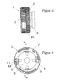
- the adapter 1 is used to connect a camera (not shown) with a (Also not shown) medical device, such as an endoscope or optics, as shown, for example, in U.S. Patent 5,882,295.
- the adapter has a substantially circular base plate 2, the on a first main surface a coupling ring 3 for connecting the camera and on the second major surface opposite the first major surface Socket 4 for connecting a flange-shaped end of the medical Device having locking elements at the free end of the socket allow fixing of the flange-shaped end in the socket.
- These locking elements are by a number of perpendicular to the plane the second major surface extending elastic tongues 5 with radially inward directed locking edges 6 formed on the outer circumference of an annular sleeve. 7 are surrounded.
- This annular sleeve 7 is opposite to the tongues 5 and the base plate 2 to a Rotatable perpendicular to the base plate 2 extending axis, wherein the annular sleeve 7 in Area of the free ends of the tongues 5 extending in the circumferential direction and Ramp-shaped radially inwardly projecting projections 8, which at a Rotation of the annular sleeve 7 relative to the base plate in a first direction with the outer circumference of the tongues 5 come into engagement and these increasingly radially press inwards so that one in which bounded by the tongues 5 Interior to be arranged flange end of the medical device between the base plate 2 and the locking edges 6 of the tongues is clamped.
- the base plate 2 has an axial direction away from the second main surface extending peripheral flange 10 for guiding the rotational movement of the annular sleeve. 7 having.
- the annular sleeve has in the manner shown in particular in Figure 6 a way Outer ring part and an inner ring part, which at the free end together are connected and form a groove between them, in which the peripheral flange can intervene.
- the inner ring part carries here the ramps 8.
- the peripheral flange 10 of the base plate 2 and the annular sleeve 7 have interlocking fasteners 13, 14, which the annular sleeve 7 in Set axial direction relative to the base plate 2, but a free rotation of the Ring sleeve 7 allow.
- These fasteners can by an annular groove 13 on the outer circumference of the Circumferential flange 10 and a bead 14 at the second major surface facing peripheral edge of the annular sleeve may be formed in the annular groove thirteenth can engage.
- the tongues 5 are preferably formed integrally with the base plate (2).
- the base plate 2 is provided in the first main surface with an annular groove 15 in the a clamping ring 9 can be latched, wherein between the clamping ring 9 and the Base plate 2 one end of a film tube cover can be clamped, the Camera and its connecting cables covers.
- the peripheral flange 10 and the annular sleeve 7 are preferably elastic Locking devices 11 and 12 for determining a first rotational position of Ring sleeve 7, in which the ramp-shaped projections 8, the tongues 5 release and allow the insertion of the flange-shaped end of the medical device, and a second rotational position, in which the projections 8, the tongues. 5 deform over the flange-shaped end and this with their locking edges. 6 hold tight.
Landscapes
- Physics & Mathematics (AREA)
- Health & Medical Sciences (AREA)
- Life Sciences & Earth Sciences (AREA)
- Surgery (AREA)
- Engineering & Computer Science (AREA)
- Optics & Photonics (AREA)
- Biophysics (AREA)
- Animal Behavior & Ethology (AREA)
- Pathology (AREA)
- Radiology & Medical Imaging (AREA)
- General Physics & Mathematics (AREA)
- Biomedical Technology (AREA)
- Heart & Thoracic Surgery (AREA)
- Medical Informatics (AREA)
- Molecular Biology (AREA)
- Nuclear Medicine, Radiotherapy & Molecular Imaging (AREA)
- General Health & Medical Sciences (AREA)
- Public Health (AREA)
- Veterinary Medicine (AREA)
- Mechanical Engineering (AREA)
- Multimedia (AREA)
- Astronomy & Astrophysics (AREA)
- Endoscopes (AREA)
Abstract
Description
Claims (6)
- Adapter (1) zum Verbinden einer Kamera mit einem medizinischen Gerät, beispielsweise einem Endoskop oder einer anderen Optik, wobei der Adapter eine Grundplatte (2) aufweist, die auf einer ersten Hauptfläche einen Kupplungsring (3) zum Anschluss der Kamera und auf der der ersten Hauptfläche gegenüberliegenden zweiten Hauptfläche eine Steckbuchse (4) zum Anschluss eines flanschförmigen Endes des medizinischen Gerätes aufweist, wobei Verriegelungselemente am freien Ende der Steckbuchse ein Festlegen des flanschförmigen Endes in der Steckbuchse ermöglichen,
dadurch gekennzeichnet, dass die Grundplatte (2) eine Anzahl von sich senkrecht zur Ebene der zweiten Hauptfläche erstreckenden und die Verriegelungselemente bildenden elastischen Zungen (5) mit radial nach innen gerichteten Rastkanten (6) trägt, dass die Zungen (5) am Aussenumfang von einer Ringhülse (7) umgeben sind, dass die Ringhülse (7) gegenüber den Zungen (5) und der Grundplatte (2) um eine sich senkrecht zur Grundplatte (2) erstreckende Achse drehbar ist, und dass die Ringhülse (7) im Bereich der freien Enden der Zungen (5) sich in Umfangsrichtung erstreckende und rampenförmig radial nach innen vorspringende Vorsprünge (8) aufweist, die bei einer Verdrehung der Ringhülse (7) gegenüber der Grundplatte in einer ersten Richtung mit dem Aussenumfang der Zungen (5) in Eingriff kommen und diese zunehmend radial nach innen drücken, so dass der in dem von den Zungen (5) umgrenzten Innenbereich anzuordnende Ringflansch des medizinischen Gerätes zwischen der Grundplatte (2) und den Rastkanten (6) der Zungen eingeklemmt wird - Adapter nach Anspruch 1, dadurch gekennzeichnet, dass die Grundplatte (2) einen sich in Axialrichtung von der zweiten Hauptfläche fort erstreckenden Umfangsflansch (10) zur Führung der Drehbewegung der Ringhülse (7) aufweist.
- Adapter nach Anspruch 1 oder 2, dadurch gekennzeichnet, dass der Umfangsflansch (10) und die Ringhülse (7) elastische Rasteinrichtungen (11, 12) zur Festlegung einer ersten Drehstellung der Ringhülse (7), in der die rampenförmigen Vorsprünge (8) die Zungen (5) freigeben und das Einsetzen des flanschförmigen Endes des medizinischen Gerätes ermöglichen, und einer zweiten Drehstellung aufweisen, in der die Vorsprünge (8) die Zungen (5) über das flanschförmige Ende verformen und dieses mit ihren Rastkanten (6) festhalten.
- Adapter nach einem der Ansprüche 1 bis 3, dadurch gekennzeichnet, dass der Umfangsflansch (10) der Grundplatte (2) und die Ringhülse (7) ineinandergreifende Befestigungselemente (13, 14) aufweisen, die die Ringhülse (7) in Axialrichtung gegenüber der Grundplatte (2) festlegen, jedoch eine Drehung der Ringhülse (7) ermöglichen.
- Adapter nach Anspruch 4, dadurch gekennzeichnet, dass die Befestigungselemente (13, 14) durch eine Ringnut (13) am Aussenumfang des Umfangsflansches (10) und eine Umbördelung (14) an dem der zweiten Hauptfläche zugewandten Umfangsrand der Ringhülse (7) gebildet sind, die in die Ringnut (13) einrastbar ist.
- Adapter nach einem der vorhergehenden Ansprüche, dadurch gekennzeichnet, dass die Grundplatte (2) in der ersten Hauptfläche eine Ringnut (15) aufweist, in die ein Klemmring (9) einrastbar ist, und dass zwischen dem Klemmring (9) und der Grundplatte (2) ein Ende einer Folienschlauchabdeckung einklemmbar ist, die die Kamera und deren Anschlussleitungen abdeckt.
Applications Claiming Priority (2)
| Application Number | Priority Date | Filing Date | Title |
|---|---|---|---|
| DE20314780U DE20314780U1 (de) | 2003-09-23 | 2003-09-23 | Adapter zum Verbinden einer Kamera mit einem medizinischen Gerät |
| DE20314780U | 2003-09-23 |
Publications (2)
| Publication Number | Publication Date |
|---|---|
| EP1518491A1 true EP1518491A1 (de) | 2005-03-30 |
| EP1518491B1 EP1518491B1 (de) | 2013-04-10 |
Family
ID=30010835
Family Applications (1)
| Application Number | Title | Priority Date | Filing Date |
|---|---|---|---|
| EP04022733.2A Expired - Lifetime EP1518491B1 (de) | 2003-09-23 | 2004-09-23 | Adapter zum Verbinden einer Kamera mit einem medizinischen Gerät |
Country Status (4)
| Country | Link |
|---|---|
| EP (1) | EP1518491B1 (de) |
| DE (1) | DE20314780U1 (de) |
| ES (1) | ES2427039T3 (de) |
| PT (1) | PT1518491E (de) |
Cited By (2)
| Publication number | Priority date | Publication date | Assignee | Title |
|---|---|---|---|---|
| EP2003482A1 (de) * | 2007-06-11 | 2008-12-17 | Swarovski-Optik KG | Adapter zur Verbindung eines optischen Aufzeichnungsgeräts mit einem Beobachtungsgerät |
| DE102015000251A1 (de) | 2015-01-16 | 2016-07-21 | Karl Storz Gmbh & Co. Kg | Adaptervorrichtung für Endoskop und Smartphone |
Citations (7)
| Publication number | Priority date | Publication date | Assignee | Title |
|---|---|---|---|---|
| DE3341876A1 (de) * | 1983-11-19 | 1985-05-30 | Lemke GmbH, 8038 Gröbenzell | Kupplung zur verbindung optischer geraete |
| US4522196A (en) * | 1982-06-11 | 1985-06-11 | Cunningham Frank W | Reusable, sterile covering for a surgical camera |
| DE3541855A1 (de) * | 1984-11-30 | 1986-06-05 | Olympus Optical Co., Ltd., Tokio/Tokyo | Verbindungsvorrichtung |
| DE9413384U1 (de) * | 1993-08-13 | 1994-10-13 | Schich, Gisbert, 91522 Ansbach | Optischer Bild- bzw. Strahlenteiler für Endoskope |
| DE29616666U1 (de) | 1996-09-27 | 1997-01-23 | KAPPA messtechnik GmbH, 37130 Gleichen | Klemmvorrichtung zum koaxialen Verbinden von zwei insbesondere optischen Bauteilen |
| EP0809976A2 (de) * | 1996-05-29 | 1997-12-03 | Udo Heisig GmbH | Folienschlauchabdeckung für medizinische Zwecke |
| US5882295A (en) | 1998-04-13 | 1999-03-16 | Spectrum Medical Industries, Inc. | Video camera drape |
Family Cites Families (4)
| Publication number | Priority date | Publication date | Assignee | Title |
|---|---|---|---|---|
| GB2174166B (en) * | 1985-04-03 | 1989-10-18 | Anthony Roy Robson | Pipe couplings |
| US4778252A (en) * | 1987-02-27 | 1988-10-18 | Newport Corporation | Self-centering holder for objects of various sizes |
| DE4444049A1 (de) * | 1994-12-10 | 1996-06-20 | Wolf Gmbh Richard | Vorrichtung für die Verbindung eines Endoskops mit einem Zusatzgerät |
| US6346073B1 (en) * | 1997-05-07 | 2002-02-12 | Pinotage, Llc | Imaging system and components thereof |
-
2003
- 2003-09-23 DE DE20314780U patent/DE20314780U1/de not_active Expired - Lifetime
-
2004
- 2004-09-23 ES ES04022733T patent/ES2427039T3/es not_active Expired - Lifetime
- 2004-09-23 EP EP04022733.2A patent/EP1518491B1/de not_active Expired - Lifetime
- 2004-09-23 PT PT04022733T patent/PT1518491E/pt unknown
Patent Citations (7)
| Publication number | Priority date | Publication date | Assignee | Title |
|---|---|---|---|---|
| US4522196A (en) * | 1982-06-11 | 1985-06-11 | Cunningham Frank W | Reusable, sterile covering for a surgical camera |
| DE3341876A1 (de) * | 1983-11-19 | 1985-05-30 | Lemke GmbH, 8038 Gröbenzell | Kupplung zur verbindung optischer geraete |
| DE3541855A1 (de) * | 1984-11-30 | 1986-06-05 | Olympus Optical Co., Ltd., Tokio/Tokyo | Verbindungsvorrichtung |
| DE9413384U1 (de) * | 1993-08-13 | 1994-10-13 | Schich, Gisbert, 91522 Ansbach | Optischer Bild- bzw. Strahlenteiler für Endoskope |
| EP0809976A2 (de) * | 1996-05-29 | 1997-12-03 | Udo Heisig GmbH | Folienschlauchabdeckung für medizinische Zwecke |
| DE29616666U1 (de) | 1996-09-27 | 1997-01-23 | KAPPA messtechnik GmbH, 37130 Gleichen | Klemmvorrichtung zum koaxialen Verbinden von zwei insbesondere optischen Bauteilen |
| US5882295A (en) | 1998-04-13 | 1999-03-16 | Spectrum Medical Industries, Inc. | Video camera drape |
Cited By (4)
| Publication number | Priority date | Publication date | Assignee | Title |
|---|---|---|---|---|
| EP2003482A1 (de) * | 2007-06-11 | 2008-12-17 | Swarovski-Optik KG | Adapter zur Verbindung eines optischen Aufzeichnungsgeräts mit einem Beobachtungsgerät |
| US7924515B2 (en) | 2007-06-11 | 2011-04-12 | Swarovski-Optik Kg. | Adapter for connecting an optical recording device to an observation device |
| CN101414042B (zh) * | 2007-06-11 | 2014-05-07 | 施华洛世奇光学公司 | 用于连接光学记录装置与观察装置的连接器 |
| DE102015000251A1 (de) | 2015-01-16 | 2016-07-21 | Karl Storz Gmbh & Co. Kg | Adaptervorrichtung für Endoskop und Smartphone |
Also Published As
| Publication number | Publication date |
|---|---|
| EP1518491B1 (de) | 2013-04-10 |
| ES2427039T3 (es) | 2013-10-28 |
| PT1518491E (pt) | 2013-07-16 |
| DE20314780U1 (de) | 2003-12-24 |
Similar Documents
| Publication | Publication Date | Title |
|---|---|---|
| DE19917549C1 (de) | Steckverbinder | |
| DE602004000434T2 (de) | Demontiereinrichtung für Schnellkupplung | |
| DE10246527B4 (de) | Klemmvorrichtung für ein Radnabenlager | |
| DE4113707C1 (de) | ||
| EP0063333A2 (de) | Anschlussvorrichtung für medizinische Instrumente oder Leitungen | |
| DE19904549C2 (de) | Durchführungsteil für mindestens ein Kabel, einen Seilzug oder dergleichen | |
| DE3541855C2 (de) | ||
| DE10328029A1 (de) | Schnellverbinder für Bewässerungssysteme insbesondere Hausbewässerung | |
| EP3586415B1 (de) | Steckerkupplung mit zugentlastung für ein verbindungskabel | |
| DE202007012036U1 (de) | Verschleißring (Protektor) | |
| EP0549860A1 (de) | Vorrichtung zum gegenseitigen Verbinden von zwei Leitungen, insbesondere Kraftstoffleitungen | |
| DE3227167A1 (de) | Befestigungsvorrichtung fuer auswechselbare zubehoerteile wie reflektoren oder dgl. an beleuchtungskoerpern, insbesondere fotografischen blitzleuchten | |
| EP1518491B1 (de) | Adapter zum Verbinden einer Kamera mit einem medizinischen Gerät | |
| DE4425705A1 (de) | Endoskopisches Instrument | |
| DE102022105564A1 (de) | Befestigungsvorrichtung | |
| DE102019107541A1 (de) | Abdichtung, dichtungseinsetzvorrichtung und dichtungseinsetzverfahren | |
| DE102005034436A1 (de) | Ringleuchte | |
| DE102021107191A1 (de) | Distales Ende mit freiem Raum zwischen Kamera und Arbeitskanal | |
| EP3679261B1 (de) | Anordnung zur kraftschlüssigen verbindung einer adapterwelle mit einer welle mittels eines spannrings | |
| EP0509410B1 (de) | Schlauchkupplung | |
| DE3524074A1 (de) | Vorrichtung zum befestigen einer schlauchschelle auf einem schlauch | |
| EP0634601A1 (de) | Anordnung zum lösbaren Verbinden von zwei mit ihren einen Enden ineinandersteckbaren Rohrteilen | |
| EP3921554A1 (de) | Gleitelement | |
| EP1055873A2 (de) | Lampe | |
| DE112013006363B4 (de) | Endoskop |
Legal Events
| Date | Code | Title | Description |
|---|---|---|---|
| PUAI | Public reference made under article 153(3) epc to a published international application that has entered the european phase |
Free format text: ORIGINAL CODE: 0009012 |
|
| AK | Designated contracting states |
Kind code of ref document: A1 Designated state(s): AT BE BG CH CY CZ DE DK EE ES FI FR GB GR HU IE IT LI LU MC NL PL PT RO SE SI SK TR |
|
| AX | Request for extension of the european patent |
Extension state: AL HR LT LV MK |
|
| 17P | Request for examination filed |
Effective date: 20050930 |
|
| AKX | Designation fees paid |
Designated state(s): AT BE BG CH CY CZ DE DK EE ES FI FR GB GR HU IE IT LI LU MC NL PL PT RO SE SI SK TR |
|
| 17Q | First examination report despatched |
Effective date: 20071017 |
|
| GRAP | Despatch of communication of intention to grant a patent |
Free format text: ORIGINAL CODE: EPIDOSNIGR1 |
|
| GRAS | Grant fee paid |
Free format text: ORIGINAL CODE: EPIDOSNIGR3 |
|
| GRAA | (expected) grant |
Free format text: ORIGINAL CODE: 0009210 |
|
| AK | Designated contracting states |
Kind code of ref document: B1 Designated state(s): AT BE BG CH CY CZ DE DK EE ES FI FR GB GR HU IE IT LI LU MC NL PL PT RO SE SI SK TR |
|
| REG | Reference to a national code |
Ref country code: GB Ref legal event code: FG4D Free format text: NOT ENGLISH |
|
| REG | Reference to a national code |
Ref country code: AT Ref legal event code: REF Ref document number: 605502 Country of ref document: AT Kind code of ref document: T Effective date: 20130415 Ref country code: CH Ref legal event code: EP |
|
| REG | Reference to a national code |
Ref country code: IE Ref legal event code: FG4D Free format text: LANGUAGE OF EP DOCUMENT: GERMAN |
|
| REG | Reference to a national code |
Ref country code: DE Ref legal event code: R096 Ref document number: 502004014104 Country of ref document: DE Effective date: 20130606 |
|
| REG | Reference to a national code |
Ref country code: PT Ref legal event code: SC4A Free format text: AVAILABILITY OF NATIONAL TRANSLATION Effective date: 20130710 |
|
| REG | Reference to a national code |
Ref country code: SE Ref legal event code: TRGR |
|
| PG25 | Lapsed in a contracting state [announced via postgrant information from national office to epo] |
Ref country code: SI Free format text: LAPSE BECAUSE OF FAILURE TO SUBMIT A TRANSLATION OF THE DESCRIPTION OR TO PAY THE FEE WITHIN THE PRESCRIBED TIME-LIMIT Effective date: 20130410 |
|
| REG | Reference to a national code |
Ref country code: NL Ref legal event code: T3 |
|
| REG | Reference to a national code |
Ref country code: ES Ref legal event code: FG2A Ref document number: 2427039 Country of ref document: ES Kind code of ref document: T3 Effective date: 20131028 |
|
| PG25 | Lapsed in a contracting state [announced via postgrant information from national office to epo] |
Ref country code: FI Free format text: LAPSE BECAUSE OF FAILURE TO SUBMIT A TRANSLATION OF THE DESCRIPTION OR TO PAY THE FEE WITHIN THE PRESCRIBED TIME-LIMIT Effective date: 20130410 Ref country code: GR Free format text: LAPSE BECAUSE OF FAILURE TO SUBMIT A TRANSLATION OF THE DESCRIPTION OR TO PAY THE FEE WITHIN THE PRESCRIBED TIME-LIMIT Effective date: 20130711 |
|
| PG25 | Lapsed in a contracting state [announced via postgrant information from national office to epo] |
Ref country code: CY Free format text: LAPSE BECAUSE OF FAILURE TO SUBMIT A TRANSLATION OF THE DESCRIPTION OR TO PAY THE FEE WITHIN THE PRESCRIBED TIME-LIMIT Effective date: 20130410 Ref country code: BG Free format text: LAPSE BECAUSE OF FAILURE TO SUBMIT A TRANSLATION OF THE DESCRIPTION OR TO PAY THE FEE WITHIN THE PRESCRIBED TIME-LIMIT Effective date: 20130710 Ref country code: PL Free format text: LAPSE BECAUSE OF FAILURE TO SUBMIT A TRANSLATION OF THE DESCRIPTION OR TO PAY THE FEE WITHIN THE PRESCRIBED TIME-LIMIT Effective date: 20130410 |
|
| REG | Reference to a national code |
Ref country code: CH Ref legal event code: NV Representative=s name: WAGNER PATENT AG, CH |
|
| PG25 | Lapsed in a contracting state [announced via postgrant information from national office to epo] |
Ref country code: SK Free format text: LAPSE BECAUSE OF FAILURE TO SUBMIT A TRANSLATION OF THE DESCRIPTION OR TO PAY THE FEE WITHIN THE PRESCRIBED TIME-LIMIT Effective date: 20130410 Ref country code: EE Free format text: LAPSE BECAUSE OF FAILURE TO SUBMIT A TRANSLATION OF THE DESCRIPTION OR TO PAY THE FEE WITHIN THE PRESCRIBED TIME-LIMIT Effective date: 20130410 Ref country code: DK Free format text: LAPSE BECAUSE OF FAILURE TO SUBMIT A TRANSLATION OF THE DESCRIPTION OR TO PAY THE FEE WITHIN THE PRESCRIBED TIME-LIMIT Effective date: 20130410 Ref country code: CZ Free format text: LAPSE BECAUSE OF FAILURE TO SUBMIT A TRANSLATION OF THE DESCRIPTION OR TO PAY THE FEE WITHIN THE PRESCRIBED TIME-LIMIT Effective date: 20130410 |
|
| PLBE | No opposition filed within time limit |
Free format text: ORIGINAL CODE: 0009261 |
|
| STAA | Information on the status of an ep patent application or granted ep patent |
Free format text: STATUS: NO OPPOSITION FILED WITHIN TIME LIMIT |
|
| PG25 | Lapsed in a contracting state [announced via postgrant information from national office to epo] |
Ref country code: RO Free format text: LAPSE BECAUSE OF FAILURE TO SUBMIT A TRANSLATION OF THE DESCRIPTION OR TO PAY THE FEE WITHIN THE PRESCRIBED TIME-LIMIT Effective date: 20130410 |
|
| REG | Reference to a national code |
Ref country code: CH Ref legal event code: PCAR Free format text: NEW ADDRESS: BAECHERSTRASSE 9, 8832 WOLLERAU (CH) |
|
| 26N | No opposition filed |
Effective date: 20140113 |
|
| BERE | Be: lapsed |
Owner name: UDO HEISIG G.M.B.H. Effective date: 20130930 |
|
| REG | Reference to a national code |
Ref country code: DE Ref legal event code: R097 Ref document number: 502004014104 Country of ref document: DE Effective date: 20140113 |
|
| PG25 | Lapsed in a contracting state [announced via postgrant information from national office to epo] |
Ref country code: MC Free format text: LAPSE BECAUSE OF FAILURE TO SUBMIT A TRANSLATION OF THE DESCRIPTION OR TO PAY THE FEE WITHIN THE PRESCRIBED TIME-LIMIT Effective date: 20130410 |
|
| GBPC | Gb: european patent ceased through non-payment of renewal fee |
Effective date: 20130923 |
|
| REG | Reference to a national code |
Ref country code: FR Ref legal event code: ST Effective date: 20140530 |
|
| REG | Reference to a national code |
Ref country code: IE Ref legal event code: MM4A |
|
| PG25 | Lapsed in a contracting state [announced via postgrant information from national office to epo] |
Ref country code: BE Free format text: LAPSE BECAUSE OF NON-PAYMENT OF DUE FEES Effective date: 20130930 Ref country code: IE Free format text: LAPSE BECAUSE OF NON-PAYMENT OF DUE FEES Effective date: 20130923 Ref country code: GB Free format text: LAPSE BECAUSE OF NON-PAYMENT OF DUE FEES Effective date: 20130923 |
|
| REG | Reference to a national code |
Ref country code: FR Ref legal event code: D3 Effective date: 20140724 |
|
| PG25 | Lapsed in a contracting state [announced via postgrant information from national office to epo] |
Ref country code: FR Free format text: LAPSE BECAUSE OF NON-PAYMENT OF DUE FEES Effective date: 20130930 |
|
| PG25 | Lapsed in a contracting state [announced via postgrant information from national office to epo] |
Ref country code: TR Free format text: LAPSE BECAUSE OF FAILURE TO SUBMIT A TRANSLATION OF THE DESCRIPTION OR TO PAY THE FEE WITHIN THE PRESCRIBED TIME-LIMIT Effective date: 20130410 |
|
| PG25 | Lapsed in a contracting state [announced via postgrant information from national office to epo] |
Ref country code: LU Free format text: LAPSE BECAUSE OF NON-PAYMENT OF DUE FEES Effective date: 20130923 Ref country code: HU Free format text: LAPSE BECAUSE OF FAILURE TO SUBMIT A TRANSLATION OF THE DESCRIPTION OR TO PAY THE FEE WITHIN THE PRESCRIBED TIME-LIMIT; INVALID AB INITIO Effective date: 20040923 |
|
| REG | Reference to a national code |
Ref country code: FR Ref legal event code: PLFP Year of fee payment: 12 |
|
| REG | Reference to a national code |
Ref country code: FR Ref legal event code: PLFP Year of fee payment: 13 |
|
| PGRI | Patent reinstated in contracting state [announced from national office to epo] |
Ref country code: FR Effective date: 20170328 |
|
| REG | Reference to a national code |
Ref country code: DE Ref legal event code: R082 Ref document number: 502004014104 Country of ref document: DE Representative=s name: PATENTANWAELTE STAEGER & SPERLING PARTNERSCHAF, DE Ref country code: DE Ref legal event code: R082 Ref document number: 502004014104 Country of ref document: DE Representative=s name: PATENTANWAELTE WALLACH, KOCH, DR. HAIBACH, FEL, DE |
|
| PGFP | Annual fee paid to national office [announced via postgrant information from national office to epo] |
Ref country code: FR Payment date: 20170403 Year of fee payment: 13 |
|
| REG | Reference to a national code |
Ref country code: FR Ref legal event code: ST Effective date: 20180531 |
|
| PG25 | Lapsed in a contracting state [announced via postgrant information from national office to epo] |
Ref country code: FR Free format text: LAPSE BECAUSE OF NON-PAYMENT OF DUE FEES Effective date: 20171002 |
|
| REG | Reference to a national code |
Ref country code: DE Ref legal event code: R082 Ref document number: 502004014104 Country of ref document: DE Representative=s name: PATENTANWAELTE STAEGER & SPERLING PARTNERSCHAF, DE |
|
| REG | Reference to a national code |
Ref country code: DE Ref legal event code: R082 Ref document number: 502004014104 Country of ref document: DE Representative=s name: PATENTANWAELTE STAEGER & SPERLING PARTNERSCHAF, DE |
|
| PGFP | Annual fee paid to national office [announced via postgrant information from national office to epo] |
Ref country code: NL Payment date: 20200925 Year of fee payment: 17 Ref country code: PT Payment date: 20200921 Year of fee payment: 17 |
|
| PGFP | Annual fee paid to national office [announced via postgrant information from national office to epo] |
Ref country code: IT Payment date: 20200922 Year of fee payment: 17 Ref country code: SE Payment date: 20200925 Year of fee payment: 17 Ref country code: AT Payment date: 20200921 Year of fee payment: 17 Ref country code: CH Payment date: 20200921 Year of fee payment: 17 |
|
| PGFP | Annual fee paid to national office [announced via postgrant information from national office to epo] |
Ref country code: ES Payment date: 20201120 Year of fee payment: 17 |
|
| REG | Reference to a national code |
Ref country code: CH Ref legal event code: PL |
|
| REG | Reference to a national code |
Ref country code: SE Ref legal event code: EUG |
|
| REG | Reference to a national code |
Ref country code: NL Ref legal event code: MM Effective date: 20211001 |
|
| REG | Reference to a national code |
Ref country code: AT Ref legal event code: MM01 Ref document number: 605502 Country of ref document: AT Kind code of ref document: T Effective date: 20210923 |
|
| PG25 | Lapsed in a contracting state [announced via postgrant information from national office to epo] |
Ref country code: PT Free format text: LAPSE BECAUSE OF NON-PAYMENT OF DUE FEES Effective date: 20220323 |
|
| PG25 | Lapsed in a contracting state [announced via postgrant information from national office to epo] |
Ref country code: NL Free format text: LAPSE BECAUSE OF NON-PAYMENT OF DUE FEES Effective date: 20211001 |
|
| PG25 | Lapsed in a contracting state [announced via postgrant information from national office to epo] |
Ref country code: SE Free format text: LAPSE BECAUSE OF NON-PAYMENT OF DUE FEES Effective date: 20210924 |
|
| PG25 | Lapsed in a contracting state [announced via postgrant information from national office to epo] |
Ref country code: LI Free format text: LAPSE BECAUSE OF NON-PAYMENT OF DUE FEES Effective date: 20210930 Ref country code: CH Free format text: LAPSE BECAUSE OF NON-PAYMENT OF DUE FEES Effective date: 20210930 Ref country code: AT Free format text: LAPSE BECAUSE OF NON-PAYMENT OF DUE FEES Effective date: 20210923 |
|
| PG25 | Lapsed in a contracting state [announced via postgrant information from national office to epo] |
Ref country code: IT Free format text: LAPSE BECAUSE OF NON-PAYMENT OF DUE FEES Effective date: 20210923 |
|
| REG | Reference to a national code |
Ref country code: ES Ref legal event code: FD2A Effective date: 20221031 |
|
| PG25 | Lapsed in a contracting state [announced via postgrant information from national office to epo] |
Ref country code: ES Free format text: LAPSE BECAUSE OF NON-PAYMENT OF DUE FEES Effective date: 20210924 |
|
| PGFP | Annual fee paid to national office [announced via postgrant information from national office to epo] |
Ref country code: DE Payment date: 20231127 Year of fee payment: 20 |
|
| REG | Reference to a national code |
Ref country code: DE Ref legal event code: R071 Ref document number: 502004014104 Country of ref document: DE |