EP1519035B1 - Soupape d'injection de combustible - Google Patents
Soupape d'injection de combustible Download PDFInfo
- Publication number
- EP1519035B1 EP1519035B1 EP20040104467 EP04104467A EP1519035B1 EP 1519035 B1 EP1519035 B1 EP 1519035B1 EP 20040104467 EP20040104467 EP 20040104467 EP 04104467 A EP04104467 A EP 04104467A EP 1519035 B1 EP1519035 B1 EP 1519035B1
- Authority
- EP
- European Patent Office
- Prior art keywords
- fuel injection
- coupler
- injection valve
- valve according
- section
- Prior art date
- Legal status (The legal status is an assumption and is not a legal conclusion. Google has not performed a legal analysis and makes no representation as to the accuracy of the status listed.)
- Expired - Lifetime
Links
- 238000002347 injection Methods 0.000 title claims description 35
- 239000007924 injection Substances 0.000 title claims description 35
- 239000000446 fuel Substances 0.000 title claims description 34
- 238000007789 sealing Methods 0.000 claims description 6
- 238000002485 combustion reaction Methods 0.000 claims description 5
- 230000036316 preload Effects 0.000 claims 1
- 239000012530 fluid Substances 0.000 description 10
- 238000011161 development Methods 0.000 description 4
- 230000018109 developmental process Effects 0.000 description 4
- 230000001419 dependent effect Effects 0.000 description 3
- 238000011144 upstream manufacturing Methods 0.000 description 2
- 238000003466 welding Methods 0.000 description 2
- 229910000831 Steel Inorganic materials 0.000 description 1
- 239000011248 coating agent Substances 0.000 description 1
- 238000000576 coating method Methods 0.000 description 1
- 238000006073 displacement reaction Methods 0.000 description 1
- 230000005284 excitation Effects 0.000 description 1
- 230000005923 long-lasting effect Effects 0.000 description 1
- 239000000463 material Substances 0.000 description 1
- 230000006903 response to temperature Effects 0.000 description 1
- 230000000284 resting effect Effects 0.000 description 1
- 239000007921 spray Substances 0.000 description 1
- 239000010959 steel Substances 0.000 description 1
Images
Classifications
-
- F—MECHANICAL ENGINEERING; LIGHTING; HEATING; WEAPONS; BLASTING
- F02—COMBUSTION ENGINES; HOT-GAS OR COMBUSTION-PRODUCT ENGINE PLANTS
- F02M—SUPPLYING COMBUSTION ENGINES IN GENERAL WITH COMBUSTIBLE MIXTURES OR CONSTITUENTS THEREOF
- F02M61/00—Fuel-injectors not provided for in groups F02M39/00 - F02M57/00 or F02M67/00
- F02M61/16—Details not provided for in, or of interest apart from, the apparatus of groups F02M61/02 - F02M61/14
- F02M61/167—Means for compensating clearance or thermal expansion
-
- F—MECHANICAL ENGINEERING; LIGHTING; HEATING; WEAPONS; BLASTING
- F02—COMBUSTION ENGINES; HOT-GAS OR COMBUSTION-PRODUCT ENGINE PLANTS
- F02M—SUPPLYING COMBUSTION ENGINES IN GENERAL WITH COMBUSTIBLE MIXTURES OR CONSTITUENTS THEREOF
- F02M51/00—Fuel-injection apparatus characterised by being operated electrically
- F02M51/06—Injectors peculiar thereto with means directly operating the valve needle
- F02M51/0603—Injectors peculiar thereto with means directly operating the valve needle using piezoelectric or magnetostrictive operating means
-
- F—MECHANICAL ENGINEERING; LIGHTING; HEATING; WEAPONS; BLASTING
- F02—COMBUSTION ENGINES; HOT-GAS OR COMBUSTION-PRODUCT ENGINE PLANTS
- F02M—SUPPLYING COMBUSTION ENGINES IN GENERAL WITH COMBUSTIBLE MIXTURES OR CONSTITUENTS THEREOF
- F02M2200/00—Details of fuel-injection apparatus, not otherwise provided for
- F02M2200/70—Linkage between actuator and actuated element, e.g. between piezoelectric actuator and needle valve or pump plunger
- F02M2200/703—Linkage between actuator and actuated element, e.g. between piezoelectric actuator and needle valve or pump plunger hydraulic
- F02M2200/705—Linkage between actuator and actuated element, e.g. between piezoelectric actuator and needle valve or pump plunger hydraulic with means for filling or emptying hydraulic chamber, e.g. for compensating clearance or thermal expansion
- F02M2200/706—Valves for filling or emptying hydraulic chamber
Definitions
- the invention relates to a fuel injection valve according to the preamble of the main claim.
- a fuel injection valve with a piezoelectric or magnetostrictive actuator which is in operative connection with a valve needle.
- the valve needle has at its discharge end a valve closing body which cooperates with a valve seat surface to a sealing seat.
- a coupler which serves to compensate for changes in length of components of the fuel injection valve, in particular of temperature-induced changes in length of the actuator, is arranged on the inflow side of the actuator module.
- the coupler has two mutually axially movable portions which engage with each other and thereby form an annular gap and a hydraulic volume.
- the annular gap connects the hydraulic volume with a balanced under a form equalization space.
- the hydraulic medium is exchanged between the hydraulic volume and the compensation chamber, wherein the annular gap serves as a throttle point.
- a disadvantage of the fuel injection valve known from the above publication is in particular that the flow resistance and the hydraulic behavior of the throttle point formed by the annular gap depends very much on temperature fluctuations. This leads, for example, in very long injection times in which is lost by the coupler much stroke that, especially at low temperatures and correspondingly high viscosity of the hydraulic medium, the stroke loss in the injection pauses can not be fully compensated by refilling the hydraulic volume, or to the fact that at high temperatures the stroke loss is unfavorably fast, even with only a short load by the Aktorbetusch Inc, the stroke loss can not be fully compensated again in only short pauses in operation.
- US 2002/139863 A1 discloses a fuel injector including a body having a longitudinal axis, a length-varying actuator, a closure member and a balance unit coupled to a second end of the actuator.
- the balancing unit is provided to axially position the actuator with respect to the body of the fuel injector in response to temperature changes.
- a first piston of the compensation unit is coupled to the first end of the actuator and has a first working surface, which forms a first fluid reservoir with an end element of the housing of the injection valve.
- a second piston has a second outer surface and a second fluid reservoir is formed between the first working surface and the second working surface.
- a communication passage connects the first and second fluid reservoirs to permit fluid to be selectively circulated between the first working surface of the first piston and a second surface of the first piston.
- the fuel injection valve according to the invention with the features of the main claim has the advantage that the hydraulic medium, in addition to the annular gap, can be additionally replaced by the duct between the hydraulic volume and compensation space.
- the hydraulic behavior of the coupler can be adjusted more easily, in particular for different temperature conditions.
- the size or the cross section through which or which hydraulic medium is exchanged between the hydraulic volume and the compensation chamber can be kept constant over a large temperature band.
- the coupler is more independent of temperature fluctuations in its hydraulic behavior.
- a throttle opening is arranged in the duct, which clearly in cross section smaller than the duct.
- the hydraulic behavior of the coupler can be further influenced advantageous.
- the at least one duct has a check valve.
- the refilling of the hydraulic volume from the expansion chamber can be completed in less time.
- the hydraulic behavior of the coupler becomes even more independent of temperature fluctuations.
- first coupler section forms a hollow cylindrical shape closed on one side into which the cylindrically shaped second coupler section at least partially engages and thereby forms the gap.
- the coupler can be constructed in a particularly simple manner.
- the coupler can be made more compact and easier.
- the first flexible section at least partially limits the first compensation space.
- the coupler can be particularly easy to build.
- the coupler can thereby be better integrated into the actuation strand of the fuel injection valve, since, for example, the flexible section can easily be arranged on the coupler so that the flexible section does not lie in the actuation axis of the actuation strand.
- the flexible section can be very easily manufactured and assembled.
- the movements of the actuator module can be transferred directly to the coupler sections and the dynamic properties of the Fuel injector are only minimally negatively affected.
- the gap, the hydraulic volume, the compensation chamber and the duct are completely filled with the, ideally made of an oil or a gel hydraulic medium.
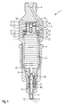
- a fuel injection valve 1 shown in an axial sectional representation in FIG. 1 is used in particular for the direct injection of fuel into a combustion chamber of a mixture-compressing, spark-ignited internal combustion engine.
- an interlocking upper housing part 4 and a coaxially arranged housing lower part 5 are a valve needle 8, an actuator 2, the internal bias is not shown, a nozzle body 6 and a hydraulic coupler 3 are arranged coaxially to each other.
- the nozzle body 6 extends from the inside with its downstream end the downstream end of the housing base 5.
- the valve needle 8, which in turn engages through the nozzle body 6 at the downstream end from the inside through a spray opening 12 has at its downstream end a valve closing body 7, which with a formed on the discharge-side end of the nozzle body 6 formed valve seat surface 13 to a sealing seat.
- actuator 2 communicates with the valve needle 8 via an actuator head 10 and an intermediate piece 9, which passes through the upper housing part 4 in the region of the discharge end of the upper housing part 4 in operative connection.
- the first spring element 21 is clamped between a shoulder 40 formed in the nozzle body 6 and a flange 26 arranged on the inflow side thereof and fixed to the valve needle 8.
- the spring force of the first spring element 21 pulls the valve closing body 7 into the sealing seat in the case of the fuel injection valve 1 that opens outward in this exemplary embodiment.
- the hydraulic coupler 3 essentially has a first coupler section 23 and a cylindrical second coupler section 24.
- the first coupler section 23 forms a one-sided, introduced in the upper housing part 4, closed opening 41 into which the second coupler section 24 engages downstream.
- One between the reason of Opening 41 and the opening 41 facing the end face of the second portion 24 befindliches hydraulic volume 36 is variable by the axial displacement of the second coupler portion 24 relative to the first coupler section 23.
- the second coupler section 24 is guided in the first coupler section 23, or in the opening 41, with a clearance 32 which, for example, is between 2 and 10 micrometers and is generated by a gap 25.
- the ratio of the minimum engagement depth of the second portion 24 to its diameter is selected so that the second portion 24 in the opening 41 can not tilt.
- the actuator 2 On the upstream side of the actuator 2, the actuator 2 is connected via a plate-shaped, on the inflow side by a second stage 43 upwardly tapering Aktorfuß 11 with the downstream end of the second coupler section 24 in operative connection, the Aktorfuß 11 and the second coupler section 24 fixed for example, materially bonded, are connected.
- the diameter of the Aktorfußes 11 is greater than that of the second coupler portion 24, wherein both components are arranged coaxially to each other.
- a second spring element 20 designed as a spiral spring in this exemplary embodiment revolves around the second coupler section 24 in the region of its downstream end.
- the second spring element 20 presses the actuator base 11 with a bias on the actuator 2, wherein the second spring element 20 is supported on the inflow side at a first stage 42 rotating around the opening 41 and on the second stage 43 downstream.
- a corrugated tube-shaped, made of steel and elastic flexible portion 27 is disposed within the second spring element 20 in this embodiment.
- the upstream end of the flexible section 27 is hermetically sealed in the region of the first step 42, for example by welding.
- the downstream end of the flexible portion 27 is in the vicinity of the Aktorfußes 11th laterally hermetically sealed at the second coupler section 24, for example by welding.
- the flexible section 27 closes off the gap 25 and, together with the region of the discharge-side end of the second coupler section 24, defines a compensation chamber 14.
- the compensation chamber 14 is connected to the hydraulic volume 36 through the gap 25.
- a conduit 15 is arranged, which in this embodiment consists of a centrally, along the longitudinal axis of the second coupler section 24 extending first bore 37, extending to the first bore 37 with a radial direction portion second bore 38 and a check valve 16 exists.
- the second bore 38 opens into the first bore 37.
- the check valve 16 is arranged, which prevents a return of hydraulic fluid from the hydraulic volume 36 into the compensation chamber 14 through the conduit 15.
- the check valve 16 consists of a in this embodiment, the first bore 37 in the direction of compensation chamber 14 conically tapered cross-sectional constriction 17, resting in the closed state on the cross-sectional constriction 17 ball body 18 and a spherical body 18 with a bias against the cross-sectional constriction 17 third third spring element pressing 19th
- the spherical body 18 is pressed by the at the bottom of the opening 41 supporting third spring element 19 so on the cross-sectional constriction 17, that the spherical body 18, the cross-sectional constriction hermetically seals in the closed state.
- the compensation chamber 14, the gap 25, the duct 15 and the hydraulic volume 36 are completely with an oil-like, gas-free and filled with incompressible hydraulic fluid.
- the flexible section 27 is diffusion-tight by the choice of materials and / or by a coating and acts on the hydraulic medium by its elasticity with a pressure.
- the actuator 2 If the actuator 2 is energized via an electrical line, not shown, it expands quickly. Since the hydraulic medium can not drain off fast enough from the hydraulic volume 36 in the compensation chamber 14, the coupler 3 behaves very hard, whereby the length of the actuator 2 acts almost completely on the valve needle 8. The valve needle 8 is moved axially against the biasing force of the first spring element 21 in the discharge direction. As a result, the sealing seat opens and the fuel, which is supplied with pressure via the fuel channel 22, which is shown only in part, is sprayed via the injection opening 12 into the combustion chamber (not shown).
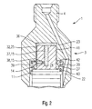
- FIG. 2 shows a fragmentary schematic representation of a second example of a partial aspect of the fuel injection valve 1 according to the invention in the region of the coupler 3, similar to the exemplary embodiment from FIG. 1.
- the duct 15 as inventive partial aspect of a first bore 37 and the second bore 38 connecting throttle opening 39, while the known from Fig. 1 check valve 16 is not shown. Due to the geometric design of the throttle bore 39, the behavior of the coupler 3 can be influenced, wherein the temperature-induced influences turn out much lower than in the gap formed as an annular gap 25.
- the gap 25 is chosen as low as possible in this, as in the first embodiment to the hydraulic behavior of the coupler 3 as possible exclusively via the conduit 15, the throttle opening 39, and to influence the check valve 16.
- the actuator 2 is supported on the hydraulic volume 36.
- the hydraulic volume 36 is chambered as free as possible.
- About the gap 25 can slowly, for a long time hydraulic fluid to flow and drain to compensate for temperature-induced changes in length, in particular of the actuator 2, with short-term actuation of the actuator 2, it comes through the coupler 3 to an unwanted stroke loss, which must be minimized.
- the leakage through the relatively narrow gap 25 is highly dependent on the viscosity of the hydraulic medium and these in turn strongly dependent on temperature.
- the leakage takes place through the gap 25 in the elastically chambered compensation chamber 14, through the flexible portion 27, which may for example also be designed as bellows.
- the second spring element 20 ensures that the hydraulic volume 36 after the end of the injection, or after corresponding temperature-induced changes in length of components, is refilled.
- the coupler 3 is a closed system, the hydraulic volume 36 follows slow temperature-induced changes in length and changes as little as possible during short-term load, or quickly refills.
- the invention is not limited to the illustrated embodiments and may, for. B. also be used for inward-opening fuel injectors.
Landscapes
- Engineering & Computer Science (AREA)
- Chemical & Material Sciences (AREA)
- Combustion & Propulsion (AREA)
- Mechanical Engineering (AREA)
- General Engineering & Computer Science (AREA)
- Fuel-Injection Apparatus (AREA)
Claims (10)
- Injecteur de carburant (1), en particulier pour l'injection directe de carburant dans une chambre de combustion d'un moteur à combustion interne, avec un actionneur (2) piézoélectrique, électrostrictif ou magnétostrictif et un obturateur de soupape (7) en liaison active avec l'actionneur (2), et coopérant avec une surface du siège de soupape (13) pour constituer un siège étanche, et avec un coupleur (3) composé d'un premier segment de coupleur (23) d'un deuxième segment de coupleur (24), les deux segments de coupleur (23, 24) étant mobiles l'un vis-à-vis de l'autre et en liaison active l'un avec l'autre au moyen d'un fluide hydraulique situé dans un volume hydraulique (36), dont au moins un des segments de coupleur (23, 24) est guidé avec un jeu réalisé par une fente (25) mettant le volume hydraulique (36) en liaison active avec au moins une chambre de compensation (14) alors qu'un canal de communication (15), dont la construction est séparée de la fente (25), relie le volume hydraulique (36) à au moins une chambre de compensation (14),
caractérisé en ce que
le canal de communication (15) est formé dans au moins l'un des segments de coupleur (23, 24), et
le canal de communication (15) est constitué d'un premier perçage (37) et d'un deuxième perçage (38) reliés par une ouverture d'étranglement (39) dont la section transversale est nettement inférieure à la section transversale restante du canal de communication (15), avec un clapet anti-retour (16) dans le passage du premier perçage (37). - Injecteur de carburant selon la revendication 1,
caractérisé en ce que
le clapet anti-retour (16) disposé dans le passage du canal de communication (15) comporte un rétrécissement (17) de la section transversale, sur lequel un corps sphérique (18) est appuyé de façon hydrauliquement étanche avec une précontrainte par un élément formant ressort (19). - Injecteur de carburant selon la revendication 2,
caractérisé en ce que
le rétrécissement (17) de la section transversale rétrécit le canal de communication (15) en direction d'au moins une chambre de compensation (14). - Injecteur de carburant selon la revendication 2 ou 3,
caractérisé en ce que
l'élément formant ressort (19) est hélicoïdal. - Injecteur de carburant selon l'une des revendications 2 à 4,
caractérisé en ce que
l'élément formant ressort (19) s'appuie contre le premier segment de coupleur (23). - Injecteur de carburant selon l'une des revendications précédentes,
caractérisé en ce que
le premier segment de coupleur (23) a une forme cylindrique creuse fermée d'un côté, dans laquelle le deuxième segment de coupleur (24) cylindrique s'engage au moins en partie et forme ainsi la fente. - Injecteur de carburant selon l'une des revendications précédentes,
caractérisé en ce qu'
un segment flexible (27) limite au moins en partie la chambre de compensation (14). - Injecteur de carburant selon la revendication 7,
caractérisé en ce que
le segment flexible (27) est en forme de disque perforé. - Injecteur de carburant selon l'une des revendications précédentes,
caractérisé en ce que
la fente (25), la chambre de compensation (14), le canal de communication (15) et le volume hydraulique (36) sont complètement remplis du fluide hydraulique. - Injecteur de carburant selon l'une des revendications précédentes,
caractérisé en ce que
le fluide hydraulique est une huile ou un gel.
Applications Claiming Priority (2)
| Application Number | Priority Date | Filing Date | Title |
|---|---|---|---|
| DE10343017 | 2003-09-17 | ||
| DE2003143017 DE10343017A1 (de) | 2003-09-17 | 2003-09-17 | Brennstoffeinspritzventil |
Publications (2)
| Publication Number | Publication Date |
|---|---|
| EP1519035A1 EP1519035A1 (fr) | 2005-03-30 |
| EP1519035B1 true EP1519035B1 (fr) | 2007-02-14 |
Family
ID=34177796
Family Applications (1)
| Application Number | Title | Priority Date | Filing Date |
|---|---|---|---|
| EP20040104467 Expired - Lifetime EP1519035B1 (fr) | 2003-09-17 | 2004-09-15 | Soupape d'injection de combustible |
Country Status (2)
| Country | Link |
|---|---|
| EP (1) | EP1519035B1 (fr) |
| DE (2) | DE10343017A1 (fr) |
Families Citing this family (7)
| Publication number | Priority date | Publication date | Assignee | Title |
|---|---|---|---|---|
| DE602005005242T2 (de) | 2004-04-26 | 2009-04-02 | Isuzu Motors Ltd. | Längen-Ausgleichselement und dieses enthaltendes Kraftstoff-Einspritzventil |
| EP1813805A1 (fr) * | 2006-01-27 | 2007-08-01 | Siemens VDO Automotive S.p.A. | Ensemble de compensation pour un injecteur |
| DE102006026877A1 (de) * | 2006-06-09 | 2007-12-13 | Robert Bosch Gmbh | Kraftstoff-Einspritzvorrichtung für eine Brennkraftmaschine |
| DE602006011604D1 (de) * | 2006-08-02 | 2010-02-25 | Continental Automotive Gmbh | Anordnung zum thermischen Ausgleich in einem Einspritzventil |
| EP2141346B1 (fr) * | 2008-07-03 | 2011-01-19 | Continental Automotive GmbH | Agencement de compensation thermique et soupape d'injection |
| DE102012204216A1 (de) | 2012-03-16 | 2013-09-19 | Robert Bosch Gmbh | Baugruppe |
| JP6209764B2 (ja) * | 2013-04-08 | 2017-10-11 | 株式会社 Acr | コモンレール用燃料噴射ノズル |
Family Cites Families (6)
| Publication number | Priority date | Publication date | Assignee | Title |
|---|---|---|---|---|
| DE19839125C1 (de) * | 1998-08-27 | 2000-04-20 | Siemens Ag | Vorrichtung und Verfahren zur Dosierung von Fluid |
| DE19940055C1 (de) * | 1999-08-24 | 2001-04-05 | Siemens Ag | Dosierventil |
| DE19940054C2 (de) * | 1999-08-24 | 2003-11-27 | Siemens Ag | Dosierventil für ein unter Druck stehendes Fluid |
| EP1325227B1 (fr) * | 2000-10-11 | 2006-07-05 | Siemens VDO Automotive Corporation | Ensemble compensateur a membrane souple pour injecteur de carburant et procede correspondant |
| DE10140796A1 (de) * | 2001-08-20 | 2003-03-06 | Bosch Gmbh Robert | Brennstoffeinspritzventil |
| US6766965B2 (en) * | 2001-08-31 | 2004-07-27 | Siemens Automotive Corporation | Twin tube hydraulic compensator for a fuel injector |
-
2003
- 2003-09-17 DE DE2003143017 patent/DE10343017A1/de not_active Withdrawn
-
2004
- 2004-09-15 EP EP20040104467 patent/EP1519035B1/fr not_active Expired - Lifetime
- 2004-09-15 DE DE200450002886 patent/DE502004002886D1/de not_active Expired - Lifetime
Also Published As
| Publication number | Publication date |
|---|---|
| DE10343017A1 (de) | 2005-04-14 |
| DE502004002886D1 (de) | 2007-03-29 |
| EP1519035A1 (fr) | 2005-03-30 |
Similar Documents
| Publication | Publication Date | Title |
|---|---|---|
| EP1149237B2 (fr) | Soupape d'injection de carburant | |
| WO2001023741A1 (fr) | Soupape pour commander le passage de liquides | |
| EP2414662B1 (fr) | Dispositif hydraulique de transmission ou amplification de course | |
| EP1519035B1 (fr) | Soupape d'injection de combustible | |
| DE10019764B4 (de) | Ventil zum Steuern von Flüssigkeiten | |
| WO2009132879A2 (fr) | Dispositif d'injection de carburant | |
| DE10217594A1 (de) | Brennstoffeinspritzventil | |
| EP1853813A1 (fr) | Injecteur | |
| EP1378657B1 (fr) | Injecteur de carburant | |
| DE19946830A1 (de) | Ventil zum Steuern von Flüssigkeiten | |
| DE10353045A1 (de) | Kraftstoffeinspritzventil | |
| EP1519037B1 (fr) | Soupape d'injection de carburant | |
| EP1519036B1 (fr) | Injecteur de carburant | |
| EP1538331B1 (fr) | Soupape d'injection de carburant | |
| DE10360450A1 (de) | Brennstoffeinspritzventil | |
| DE10353641B4 (de) | Brennstoffeinspritzventil | |
| EP1664525B1 (fr) | Dispositif de dosage | |
| EP1519034B1 (fr) | Soupape d'injection de carburant | |
| DE10332090B4 (de) | Brennstoffeinspritzventil | |
| DE10123174A1 (de) | Ventil zum Steuern von Flüssigkeiten | |
| EP1544454B1 (fr) | Injecteur de carburant | |
| DE102006013958B4 (de) | Brennstoffeinspritzventil | |
| EP1450034B1 (fr) | Injecteur de carburant | |
| EP1452727A1 (fr) | Injecteur de carburant | |
| EP1491760B1 (fr) | Soupape d'injection de carburant |
Legal Events
| Date | Code | Title | Description |
|---|---|---|---|
| PUAI | Public reference made under article 153(3) epc to a published international application that has entered the european phase |
Free format text: ORIGINAL CODE: 0009012 |
|
| AK | Designated contracting states |
Kind code of ref document: A1 Designated state(s): AT BE BG CH CY CZ DE DK EE ES FI FR GB GR HU IE IT LI LU MC NL PL PT RO SE SI SK TR |
|
| AX | Request for extension of the european patent |
Extension state: AL HR LT LV MK |
|
| 17P | Request for examination filed |
Effective date: 20050930 |
|
| AKX | Designation fees paid |
Designated state(s): DE FR GB IT |
|
| GRAP | Despatch of communication of intention to grant a patent |
Free format text: ORIGINAL CODE: EPIDOSNIGR1 |
|
| GRAS | Grant fee paid |
Free format text: ORIGINAL CODE: EPIDOSNIGR3 |
|
| GRAA | (expected) grant |
Free format text: ORIGINAL CODE: 0009210 |
|
| AK | Designated contracting states |
Kind code of ref document: B1 Designated state(s): DE FR GB IT |
|
| REG | Reference to a national code |
Ref country code: GB Ref legal event code: FG4D Free format text: NOT ENGLISH |
|
| REF | Corresponds to: |
Ref document number: 502004002886 Country of ref document: DE Date of ref document: 20070329 Kind code of ref document: P |
|
| GBT | Gb: translation of ep patent filed (gb section 77(6)(a)/1977) |
Effective date: 20070509 |
|
| ET | Fr: translation filed | ||
| PLBE | No opposition filed within time limit |
Free format text: ORIGINAL CODE: 0009261 |
|
| STAA | Information on the status of an ep patent application or granted ep patent |
Free format text: STATUS: NO OPPOSITION FILED WITHIN TIME LIMIT |
|
| 26N | No opposition filed |
Effective date: 20071115 |
|
| REG | Reference to a national code |
Ref country code: FR Ref legal event code: PLFP Year of fee payment: 13 |
|
| REG | Reference to a national code |
Ref country code: FR Ref legal event code: PLFP Year of fee payment: 14 |
|
| PGFP | Annual fee paid to national office [announced via postgrant information from national office to epo] |
Ref country code: FR Payment date: 20170925 Year of fee payment: 14 Ref country code: IT Payment date: 20170926 Year of fee payment: 14 Ref country code: GB Payment date: 20170925 Year of fee payment: 14 |
|
| PGFP | Annual fee paid to national office [announced via postgrant information from national office to epo] |
Ref country code: DE Payment date: 20171128 Year of fee payment: 14 |
|
| REG | Reference to a national code |
Ref country code: DE Ref legal event code: R119 Ref document number: 502004002886 Country of ref document: DE |
|
| GBPC | Gb: european patent ceased through non-payment of renewal fee |
Effective date: 20180915 |
|
| PG25 | Lapsed in a contracting state [announced via postgrant information from national office to epo] |
Ref country code: IT Free format text: LAPSE BECAUSE OF NON-PAYMENT OF DUE FEES Effective date: 20180915 Ref country code: DE Free format text: LAPSE BECAUSE OF NON-PAYMENT OF DUE FEES Effective date: 20190402 |
|
| PG25 | Lapsed in a contracting state [announced via postgrant information from national office to epo] |
Ref country code: FR Free format text: LAPSE BECAUSE OF NON-PAYMENT OF DUE FEES Effective date: 20180930 |
|
| PG25 | Lapsed in a contracting state [announced via postgrant information from national office to epo] |
Ref country code: GB Free format text: LAPSE BECAUSE OF NON-PAYMENT OF DUE FEES Effective date: 20180915 |