EP1519177B1 - Procédé de calibrage un appareil d'equilibrage des pneus et machine d'équilibrage de pneus - Google Patents
Procédé de calibrage un appareil d'equilibrage des pneus et machine d'équilibrage de pneus Download PDFInfo
- Publication number
- EP1519177B1 EP1519177B1 EP20030021761 EP03021761A EP1519177B1 EP 1519177 B1 EP1519177 B1 EP 1519177B1 EP 20030021761 EP20030021761 EP 20030021761 EP 03021761 A EP03021761 A EP 03021761A EP 1519177 B1 EP1519177 B1 EP 1519177B1
- Authority
- EP
- European Patent Office
- Prior art keywords
- measuring
- calibration
- runs
- unbalance
- force
- Prior art date
- Legal status (The legal status is an assumption and is not a legal conclusion. Google has not performed a legal analysis and makes no representation as to the accuracy of the status listed.)
- Expired - Lifetime
Links
Images

Classifications
-
- G—PHYSICS
- G01—MEASURING; TESTING
- G01M—TESTING STATIC OR DYNAMIC BALANCE OF MACHINES OR STRUCTURES; TESTING OF STRUCTURES OR APPARATUS, NOT OTHERWISE PROVIDED FOR
- G01M1/00—Testing static or dynamic balance of machines or structures
-
- G—PHYSICS
- G01—MEASURING; TESTING
- G01M—TESTING STATIC OR DYNAMIC BALANCE OF MACHINES OR STRUCTURES; TESTING OF STRUCTURES OR APPARATUS, NOT OTHERWISE PROVIDED FOR
- G01M1/00—Testing static or dynamic balance of machines or structures
- G01M1/14—Determining imbalance
Definitions
- the invention relates to a method for calibrating a wheel balancing machine, which has a rotatably mounted measuring shaft for unbalance measurement of vehicle wheels, in which at least one unbalance measuring run with bare measuring shaft and at least two further consecutive unbalance measuring runs, in which test weights with predetermined mass in two an axial distance from each other having predetermined Calibration levels are attached, carried out and depending on the case of two sensors coupled to the measuring shaft measured forces the measuring electronics and / or the measurement display of Radauswuchtmaschine is or will be set and a Radauswuchtmaschine.
- Such a method is known from EP 0 133 229 B1. So that the forces obtained in the various measuring runs are assigned to the respective associated calibration level, it is known to carry out the at least three unbalance measuring runs for the calibration in a specific sequence. For example, the measurement run with a bare measuring shaft without test weights, then the measurement run with the test weight inserted in the left calibration plane and then the measurement run with the test weight inserted in the right calibration plane are performed first. However, there is a risk that the measuring runs are reversed in their order, resulting in an incorrect calibration of the wheel balancing machine. In addition, errors of calibration occur in that two runs with bare measuring shaft and a test run is carried out with a test weight in one of the two calibration planes.
- the object of the invention is therefore to provide a method of the type mentioned, in which, regardless of the sequence of performed in the calibration unbalance measurement runs a correct calibration of Radauswuchtmaschine is achieved.
- the forces measured by one of the two measuring sensors in the at least three unbalance measuring runs are correlated with each other, whereby the lowest force of the three measured forces is assigned to the unbalance measuring run with the bare measuring shaft and the forces measured in the at least two further measuring runs be assigned due to their differences of the respective associated calibration level.
- the greater force is assigned to the calibration plane, which lies farther away from the encoder, and the lower force is assigned to the calibration plane, which is closer to the encoder.
- the invention is suitable for calibrating wheel balancers, in which the measuring sensors coupled to the measuring shaft are arranged at an axial distance from one another, as is known, for example, from EP 0 133 229 B1.
- this calibration can also be carried out in wheel balancers such as are known from EP 1 108 204 B1 or from EP 0 058 860 B1.
- the test weight which has a mass of, for example, 100 g, is fixed in the successive measuring runs with a specific angular difference in the calibration planes on the measuring shaft in equal radii.
- the attachment can be done on a dynamically balanced rotor which is fixed to the measuring shaft.
- the angle difference is 180 °.
- vectorially the imbalance vector which was determined during the calibration run of the bare measuring shaft without test weight is subtracted.
- any residual imbalance of the bare measuring shaft has a different effect on the unbalance determined in the two calibration runs.
- the vector substraction described above compensates for this different influence.
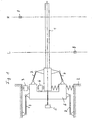
- the figures show a wheel balancing machine with a measuring arrangement, as it is known from EP 1 108 204 B1.
- a measuring shaft of the wheel balancing machine is supported with pretensioning via two measuring sensors 3, 4 and an intermediate frame 6 relative to the machine frame 2.
- a test weight 8 for example, with a calibration mass of 100 g in a certain radius in a left calibration plane L on the measuring shaft 1 are attached. Furthermore, the test weight 8 can be fixed to the measuring shaft 1 in a right-hand calibration plane R at the same radial distance as in the left-hand calibration plane.
- the calibration planes L and R may be different from the balancing planes of a wheel to be balanced or have the same position as the balancing planes.
- a calibration run is performed with bare measuring shaft 1 without test weight.
- a force F 03 is measured by the encoder 3 and a force F 04 by the encoder 4.
- the measurement of the forces in the encoders 3 and 4 takes place with reference to the angle using the rotary encoder 5.
- the measuring electronics 9 of the balancing machine forms from these measurement results an unbalance vector U 0 in a known manner.
- test weight 8 in the left calibration plane L is fixed to the measuring shaft 1 in the predetermined radius.
- 3 and 4 forces K L3 and K L4 are measured by the encoders, which result from the centrifugal forces generated by the test weight 8. These forces are measured angle-related using the rotary encoder 5 and from this an unbalance vector U L determined by the measuring electronics 9 for the imbalance display on the machine.
- test weight 8 is attached to the measuring shaft 1 at the same distance as in the left calibration plane L in the right calibration plane R.
- 3 and 4 forces K R3 and K R4 are measured by the encoders, from which with the aid of the rotary encoder 5, an unbalance vector U R determined using the machine electronics 9 and displayed on the display device.
- an additional evaluation of the force signals generated by at least one of the two encoders 3 and 4 is performed in the invention.
- the forces of the encoder 3 are evaluated.
- the encoder 3 supplies during the above-described successive calibration runs the force signals F 03 , F L3 and F R3 . Due to the different lever arms, which act on insertion of the test weight 8 into the left and the right calibration plane, F R3 > F L3 > F 03 .
- an additional evaluation device 11 which may also be integrated into the machine or measuring electronics 9, this is detected from the difference in forces resulting order. With the aid of the evaluation device 11, the largest force F R3 is assigned to the calibration run, in which the test weight 8 was arranged in the right-hand calibration plane R, and thus assigned to the unbalance vector U R determined for this purpose.
- the second largest force F L3 is assigned to the calibration run, in which the test weight 8 was arranged in the left calibration plane L, and thus assigned to the imbalance vector U L determined in this case.
- the smallest measured force F 03 is assigned to the calibration run, in which the bare measuring shaft 1 circulated, assigned to the imbalance vector U 0 determined in the process.
- the assignment of the determined imbalance vectors to the calibration planes is performed.
- the calibration can be carried out in a known manner such that for the left calibration level L corresponding electrical or electronic components of the measuring electronics 9 and / or the display device 10 with a on the Machine provided actuator, for example in the form of a knob, are adjusted until the display of the unbalance vector in the right calibration level R is zero.
- corresponding electronic or electrical components of the measuring electronics 9 or display device 10 can be adjusted so that the imbalance vector display for the left calibration level L is zero or disappears and only the vector display for the right Kibribrierebene R is present. Furthermore, an approximation of the mass display and angle display for the respective calibration level can be done.
- the described assignment of the determined unbalance vectors to the associated calibration runs and thus to the associated calibration planes can be carried out in such balancing machines in which different distances of the calibration planes of the at least one encoder of the measuring arrangement are present.
- the invention thus shows a method and a device for calibrating a wheel balancing machine which has a rotatably mounted measuring shaft 1 for unbalance measurement of a vehicle wheel, in which a test weight 8 is arranged chronologically successively in a left calibration plane L and a right calibration plane R and thereby calibration runs are performed , And further with bare measuring shaft 1, a calibration run is performed.
- These calibration runs can be performed on each other in any order.
- the forces measured by at least one of the two encoders 3, 4 in the three calibration runs are evaluated with respect to their differences, the lowest force being the calibration gage with the bare measuring shaft 1, the largest measured force of the calibration plane R farthest from the giver lies, and the intervening Force of the calibration plane L, which is closer to the encoder, are assigned for the calibration of the wheel balancing machine.
- an angular difference of in particular 180 ° for the attachment points of the test weight in the calibration planes is preferred;
- the attachment points in the two calibration planes can also have the same angular position.
Landscapes
- Physics & Mathematics (AREA)
- General Physics & Mathematics (AREA)
- Testing Of Balance (AREA)
Claims (5)
- Procédé pour étalonner une machine à équilibrer les roues munie d'un arbre de mesure monté tournant et destiné à mesurer le balourd de roues de véhicule, d'après lequel on exécute au moins une opération de mesure de balourd à l'aide du seul arbre de mesure et au moins deux autres opérations de mesure de balourd successives pendant lesquelles un poids d'essai à masse prédéfinie est respectivement fixé à deux plans d'étalonnage prédéfinis et placés à distance axiale l'un par rapport à l'autre, et d'après lequel on règle l'électronique de mesure et/ou l'installation d'affichage de la machine à équilibrer les roues en fonction des forces alors mesurées à l'aide de deux indicateurs de force couplés par combinaison de forces à l'arbre de mesure,
caractérisé en ce que les forces respectivement mesurées pendant les trois opérations de mesure de balourd par au moins un des deux indicateurs de force sont mises en rapport l'une avec l'autre quant à leurs différences, la force la plus petite étant associée à l'opération de mesure de balourd à l'aide du seul arbre de mesure et les forces mesurées pendant les au moins deux autres opérations de mesure sont associées, sur la base de leurs différences, au plan d'étalonnage respectivement correspondant, et pour régler l'étalonnage la force la plus grande est associée au plan d'étalonnage qui est plus éloigné de l'au moins un indicateur de force et la force la plus petite au plan d'étalonnage qui est plus proche de l'au moins un indicateur de force. - Procédé selon la revendication 1, caractérisé en ce que le poids d'essai est fixé à l'arbre de mesure en faisant une différence d'angle prédéfinie pendant les opérations d'étalonnage.
- Procédé selon la revendication 2, caractérisé en ce que la différence d'angle est de 180°.
- Procédé selon l'une des revendications 1 à 3, caractérisé en ce que le vecteur de balourd qui a été déterminé lors de l'opération de mesure à l'aide du seul arbre de mesure est soustrait vectoriellement des vecteurs de balourd déterminés à l'aide du poids d'essai pendant les opérations de mesure de balourd.
- Machine à équilibrer les roues comportant un arbre de mesure (1) à entraîner en rotation, au moins deux indicateurs de force (3, 4) reliés par combinaison de forces à l'arbre de mesure (1), un générateur d'angle de rotation (5) qui est relié à l'arbre de mesure (1) et qui fournit des signaux d'angle proportionnels aux angles de rotation de l'arbre de mesure (1), une électronique de mesure (9) à laquelle sont raccordés les indicateurs de force (3, 4) et le générateur d'angle de rotation (5) et une installation d'affichage (10) pour afficher les vecteurs de balourd déterminés pour une roue de véhicule à fixer à l'arbre de mesure (1),
caractérisé en ce qu'à au moins un des indicateurs de force (3, 4) est raccordée une installation d'exploitation (11) qui lors d'un processus d'étalonnage détecte les forces mesurées pendant au moins trois opérations d'étalonnage à l'aide du seul arbre de mesure (1) et pendant deux autres opérations d'étalonnage à l'aide d'un poids d'essai (8) placé dans un plan d'étalonnage gauche (L) et dans un plan d'étalonnage droit (R) ainsi que les différences entre les forces mesurées et associe aux deux plans d'étalonnage (L, R) en fonction des différences entre les forces mesurées les vecteurs de balourd (UL, UR) déterminés pendant les opérations d'étalonnage.
Priority Applications (2)
| Application Number | Priority Date | Filing Date | Title |
|---|---|---|---|
| EP20030021761 EP1519177B1 (fr) | 2003-09-25 | 2003-09-25 | Procédé de calibrage un appareil d'equilibrage des pneus et machine d'équilibrage de pneus |
| DE50303119T DE50303119D1 (de) | 2003-09-25 | 2003-09-25 | Verfahren zur Kalibrierung einer Radauswuchtmaschine und Radauswuchtmaschine |
Applications Claiming Priority (1)
| Application Number | Priority Date | Filing Date | Title |
|---|---|---|---|
| EP20030021761 EP1519177B1 (fr) | 2003-09-25 | 2003-09-25 | Procédé de calibrage un appareil d'equilibrage des pneus et machine d'équilibrage de pneus |
Publications (2)
| Publication Number | Publication Date |
|---|---|
| EP1519177A1 EP1519177A1 (fr) | 2005-03-30 |
| EP1519177B1 true EP1519177B1 (fr) | 2006-04-26 |
Family
ID=34178502
Family Applications (1)
| Application Number | Title | Priority Date | Filing Date |
|---|---|---|---|
| EP20030021761 Expired - Lifetime EP1519177B1 (fr) | 2003-09-25 | 2003-09-25 | Procédé de calibrage un appareil d'equilibrage des pneus et machine d'équilibrage de pneus |
Country Status (2)
| Country | Link |
|---|---|
| EP (1) | EP1519177B1 (fr) |
| DE (1) | DE50303119D1 (fr) |
Families Citing this family (3)
| Publication number | Priority date | Publication date | Assignee | Title |
|---|---|---|---|---|
| CN109238565A (zh) * | 2018-08-29 | 2019-01-18 | 深圳市元征科技股份有限公司 | 一种轮胎平衡机校准提示方法、系统及相关设备 |
| CN113532733B (zh) * | 2021-08-27 | 2023-08-08 | 四川大学 | 一种薄膜式压力传感器校准装置及校准方法 |
| CN114778003B (zh) * | 2022-05-24 | 2025-09-26 | 桂林施瑞德科技发展有限公司 | 一种自动校准的车轮动平衡机及其运行方法 |
Family Cites Families (2)
| Publication number | Priority date | Publication date | Assignee | Title |
|---|---|---|---|---|
| US4494400A (en) * | 1983-07-28 | 1985-01-22 | Fmc Corporation | Wheel balancer two plane calibration apparatus and method |
| US5396436A (en) * | 1992-02-03 | 1995-03-07 | Hunter Engineering Corporation | Wheel balancing apparatus and method with improved calibration and improved imbalance determination |
-
2003
- 2003-09-25 DE DE50303119T patent/DE50303119D1/de not_active Expired - Lifetime
- 2003-09-25 EP EP20030021761 patent/EP1519177B1/fr not_active Expired - Lifetime
Also Published As
| Publication number | Publication date |
|---|---|
| DE50303119D1 (de) | 2006-06-01 |
| EP1519177A1 (fr) | 2005-03-30 |
Similar Documents
| Publication | Publication Date | Title |
|---|---|---|
| EP0247350B1 (fr) | Procédé et dispositif pour optimiser l'équilibrage d'une roue de véhicule | |
| DE102008006865B4 (de) | Induktiver Drehmomentsensor | |
| DE4143624C2 (de) | Auswuchtmaschine für Kraftfahrzeugräder | |
| DE102016005889B4 (de) | Wellengenauigkeitsmessvorrichtung zum Messen der Genauigkeit einer Abtriebswelle eines Motors | |
| WO2000014503A1 (fr) | Dispositif pour mesurer des forces produites par un defaut d'equilibrage d'un rotor | |
| EP0273063B1 (fr) | Méthode pour calibrer un appareil d'équilibrage | |
| EP0942273B1 (fr) | Méthode pour déterminer la compensation du déséquilibre des rotors élastiques | |
| DE19527062A1 (de) | Verfahren und Vorrichtung zur Kalibrierung von Drehmoment-Meßeinrichtungen | |
| EP0590169B1 (fr) | Procédé pour la détermination du balourd d'un rotor inflexible entraîné en rotation | |
| DE69200882T2 (de) | Verfahren zur Korrektur der Unwucht eines kranzeingepassten Reifens. | |
| EP1519177B1 (fr) | Procédé de calibrage un appareil d'equilibrage des pneus et machine d'équilibrage de pneus | |
| DE2827669C2 (de) | Verfahren zur Ermittlung der Größe und Phasenlage von durch Meßwertaufnehmer erfaßten Schwingungen, insbesondere in der Auswuchttechnik | |
| DE10206259B4 (de) | Verfahren zur Korrektur von Lateralkraftmesswerten | |
| DE69413622T2 (de) | Verfahren zur Unwuchtkorrektur von einem auf einer Felge montierten Reifen | |
| DE3040713C2 (de) | Vorrichtung zum Einstellen einer kraftmessenden Auswuchtmaschine | |
| DE3002682A1 (de) | Verfahren und vorrichtung zur massenungleichfoermigkeitsmessung an einem rotor, insbesondere kreisel | |
| DE2847295C2 (de) | Vorrichtung zur Bestimmung der Unwucht eines von einer Aufnahme einer Auswuchtmaschine mit Lagerständer gehaltenen Rotationskörpers | |
| DE3026232C2 (de) | Verfahren und Vorrichtung zur Größenanzeige einer Unwucht beim Auswuchten von Rotoren | |
| EP1231457B1 (fr) | Procédé et dispositif de calibrage d'un dispositif de mesure de balourd | |
| EP0797086B1 (fr) | Système d'équilibrage d'un pneu de véhicule | |
| EP0259513B1 (fr) | Procédé pour mesurer avec précision le carrosage et l'inclination du pivot de véhicules | |
| DE10056956B4 (de) | Verfahren und Vorrichtung zum Beurteilen einer exzentrischen Position eines Beschleunigungssensors | |
| DE102017002891A1 (de) | Verfahren zur Bestimmung einer Fahrwerksgeometrie | |
| DE19813881A1 (de) | Verfahren zur Ermittlung einer Unwucht sowie Vorrichtung | |
| DE3231852A1 (de) | Verfahren und vorrichtung zur qualitaetspruefung von reifen, insbesondere kraftfahrzeugreifen |
Legal Events
| Date | Code | Title | Description |
|---|---|---|---|
| PUAI | Public reference made under article 153(3) epc to a published international application that has entered the european phase |
Free format text: ORIGINAL CODE: 0009012 |
|
| 17P | Request for examination filed |
Effective date: 20040924 |
|
| AK | Designated contracting states |
Kind code of ref document: A1 Designated state(s): AT BE BG CH CY CZ DE DK EE ES FI FR GB GR HU IE IT LI LU MC NL PT RO SE SI SK TR |
|
| AX | Request for extension of the european patent |
Extension state: AL LT LV MK |
|
| GRAP | Despatch of communication of intention to grant a patent |
Free format text: ORIGINAL CODE: EPIDOSNIGR1 |
|
| GRAS | Grant fee paid |
Free format text: ORIGINAL CODE: EPIDOSNIGR3 |
|
| AKX | Designation fees paid |
Designated state(s): DE ES FR GB IT |
|
| GRAA | (expected) grant |
Free format text: ORIGINAL CODE: 0009210 |
|
| AK | Designated contracting states |
Kind code of ref document: B1 Designated state(s): DE ES FR GB IT |
|
| PG25 | Lapsed in a contracting state [announced via postgrant information from national office to epo] |
Ref country code: GB Free format text: LAPSE BECAUSE OF FAILURE TO SUBMIT A TRANSLATION OF THE DESCRIPTION OR TO PAY THE FEE WITHIN THE PRESCRIBED TIME-LIMIT Effective date: 20060426 |
|
| REG | Reference to a national code |
Ref country code: GB Ref legal event code: FG4D Free format text: NOT ENGLISH |
|
| REF | Corresponds to: |
Ref document number: 50303119 Country of ref document: DE Date of ref document: 20060601 Kind code of ref document: P |
|
| REG | Reference to a national code |
Ref country code: DE Ref legal event code: R096 Ref document number: 50303119 Country of ref document: DE Effective date: 20060601 |
|
| PG25 | Lapsed in a contracting state [announced via postgrant information from national office to epo] |
Ref country code: ES Free format text: LAPSE BECAUSE OF FAILURE TO SUBMIT A TRANSLATION OF THE DESCRIPTION OR TO PAY THE FEE WITHIN THE PRESCRIBED TIME-LIMIT Effective date: 20060806 |
|
| GBV | Gb: ep patent (uk) treated as always having been void in accordance with gb section 77(7)/1977 [no translation filed] |
Effective date: 20060426 |
|
| ET | Fr: translation filed | ||
| PLBE | No opposition filed within time limit |
Free format text: ORIGINAL CODE: 0009261 |
|
| STAA | Information on the status of an ep patent application or granted ep patent |
Free format text: STATUS: NO OPPOSITION FILED WITHIN TIME LIMIT |
|
| 26N | No opposition filed |
Effective date: 20070129 |
|
| REG | Reference to a national code |
Ref country code: DE Ref legal event code: R097 Ref document number: 50303119 Country of ref document: DE Effective date: 20070129 |
|
| REG | Reference to a national code |
Ref country code: FR Ref legal event code: PLFP Year of fee payment: 14 |
|
| REG | Reference to a national code |
Ref country code: FR Ref legal event code: PLFP Year of fee payment: 15 |
|
| PGFP | Annual fee paid to national office [announced via postgrant information from national office to epo] |
Ref country code: FR Payment date: 20170925 Year of fee payment: 15 |
|
| PGFP | Annual fee paid to national office [announced via postgrant information from national office to epo] |
Ref country code: DE Payment date: 20171005 Year of fee payment: 15 |
|
| REG | Reference to a national code |
Ref country code: DE Ref legal event code: R119 Ref document number: 50303119 Country of ref document: DE |
|
| PG25 | Lapsed in a contracting state [announced via postgrant information from national office to epo] |
Ref country code: DE Free format text: LAPSE BECAUSE OF NON-PAYMENT OF DUE FEES Effective date: 20190402 |
|
| PG25 | Lapsed in a contracting state [announced via postgrant information from national office to epo] |
Ref country code: FR Free format text: LAPSE BECAUSE OF NON-PAYMENT OF DUE FEES Effective date: 20180930 |
|
| PGFP | Annual fee paid to national office [announced via postgrant information from national office to epo] |
Ref country code: IT Payment date: 20220926 Year of fee payment: 20 |
|
| P01 | Opt-out of the competence of the unified patent court (upc) registered |
Effective date: 20230517 |