EP1526008A1 - Chaíne à neige, pièce pour celle-ci et méthode pour placer une telle chaíne à neige - Google Patents
Chaíne à neige, pièce pour celle-ci et méthode pour placer une telle chaíne à neige Download PDFInfo
- Publication number
- EP1526008A1 EP1526008A1 EP04077878A EP04077878A EP1526008A1 EP 1526008 A1 EP1526008 A1 EP 1526008A1 EP 04077878 A EP04077878 A EP 04077878A EP 04077878 A EP04077878 A EP 04077878A EP 1526008 A1 EP1526008 A1 EP 1526008A1
- Authority
- EP
- European Patent Office
- Prior art keywords
- wheel
- disc
- shaped element
- snow chain
- chain
- Prior art date
- Legal status (The legal status is an assumption and is not a legal conclusion. Google has not performed a legal analysis and makes no representation as to the accuracy of the status listed.)
- Withdrawn
Links
- 238000000034 method Methods 0.000 title claims abstract description 10
- 239000004033 plastic Substances 0.000 claims abstract description 12
- 229920003023 plastic Polymers 0.000 claims abstract description 12
- 229920001169 thermoplastic Polymers 0.000 claims description 5
- 239000004416 thermosoftening plastic Substances 0.000 claims description 5
- 230000007704 transition Effects 0.000 claims description 4
- 229920001971 elastomer Polymers 0.000 claims description 3
- 239000005060 rubber Substances 0.000 claims description 2
- 230000001012 protector Effects 0.000 abstract description 16
- 238000005260 corrosion Methods 0.000 description 8
- 230000007797 corrosion Effects 0.000 description 8
- 239000000463 material Substances 0.000 description 5
- 238000010438 heat treatment Methods 0.000 description 4
- 238000004519 manufacturing process Methods 0.000 description 4
- 230000002411 adverse Effects 0.000 description 3
- 238000003825 pressing Methods 0.000 description 3
- 150000003839 salts Chemical class 0.000 description 3
- 239000011248 coating agent Substances 0.000 description 2
- 238000000576 coating method Methods 0.000 description 2
- 238000006073 displacement reaction Methods 0.000 description 2
- 230000000694 effects Effects 0.000 description 2
- 229910001234 light alloy Inorganic materials 0.000 description 2
- 230000000717 retained effect Effects 0.000 description 2
- XLYOFNOQVPJJNP-UHFFFAOYSA-N water Substances O XLYOFNOQVPJJNP-UHFFFAOYSA-N 0.000 description 2
- 239000005062 Polybutadiene Substances 0.000 description 1
- 239000004698 Polyethylene Substances 0.000 description 1
- 229920002367 Polyisobutene Polymers 0.000 description 1
- PMZURENOXWZQFD-UHFFFAOYSA-L Sodium Sulfate Chemical compound [Na+].[Na+].[O-]S([O-])(=O)=O PMZURENOXWZQFD-UHFFFAOYSA-L 0.000 description 1
- 238000009825 accumulation Methods 0.000 description 1
- 239000000654 additive Substances 0.000 description 1
- 238000010276 construction Methods 0.000 description 1
- 238000005520 cutting process Methods 0.000 description 1
- 230000003670 easy-to-clean Effects 0.000 description 1
- 239000000806 elastomer Substances 0.000 description 1
- 239000005038 ethylene vinyl acetate Substances 0.000 description 1
- 238000002474 experimental method Methods 0.000 description 1
- 239000002184 metal Substances 0.000 description 1
- 229920003052 natural elastomer Polymers 0.000 description 1
- 229920001194 natural rubber Polymers 0.000 description 1
- 229920002857 polybutadiene Polymers 0.000 description 1
- -1 polyethylene Polymers 0.000 description 1
- 229920000573 polyethylene Polymers 0.000 description 1
- 229920000642 polymer Polymers 0.000 description 1
- 229920002635 polyurethane Polymers 0.000 description 1
- 239000004814 polyurethane Substances 0.000 description 1
- 239000004800 polyvinyl chloride Substances 0.000 description 1
- 230000002035 prolonged effect Effects 0.000 description 1
- 230000001681 protective effect Effects 0.000 description 1
- 238000007493 shaping process Methods 0.000 description 1
- 238000003860 storage Methods 0.000 description 1
Images


Classifications
-
- B—PERFORMING OPERATIONS; TRANSPORTING
- B60—VEHICLES IN GENERAL
- B60C—VEHICLE TYRES; TYRE INFLATION; TYRE CHANGING; CONNECTING VALVES TO INFLATABLE ELASTIC BODIES IN GENERAL; DEVICES OR ARRANGEMENTS RELATED TO TYRES
- B60C27/00—Non-skid devices temporarily attachable to resilient tyres or resiliently-tyred wheels
- B60C27/006—Non-skid devices temporarily attachable to resilient tyres or resiliently-tyred wheels provided with protective parts, e.g. rubber elements to protect the rim portion
-
- B—PERFORMING OPERATIONS; TRANSPORTING
- B60—VEHICLES IN GENERAL
- B60C—VEHICLE TYRES; TYRE INFLATION; TYRE CHANGING; CONNECTING VALVES TO INFLATABLE ELASTIC BODIES IN GENERAL; DEVICES OR ARRANGEMENTS RELATED TO TYRES
- B60C27/00—Non-skid devices temporarily attachable to resilient tyres or resiliently-tyred wheels
- B60C27/06—Non-skid devices temporarily attachable to resilient tyres or resiliently-tyred wheels extending over the complete circumference of the tread, e.g. made of chains or cables
Definitions
- the invention relates to a snow chain for a tyre mounted on a wheel of a vehicle, which snow chain at least comprises an assembly of chains to be fitted and tensioned round the tyre and the wheel, wherein a disc-shaped element having a diameter at least equal to the diameter of the wheel can be fitted between the wheel and the assembly of chains.
- Snow chains are generally known, they are in particular used on vehicles in snow (winter sports) areas.
- the chain assembly is fitted round the tyre and the wheel and subsequently tensioned.
- the chain assembly tightly fits round the tyre, so as to give the tyre increased traction on the road surface when driving in wintry conditions.
- a drawback of the snow chains that are currently known is the fact that the chain assembly also abuts tightly against the wheel. While driving, and in particular during steering manoeuvres, the chain assembly is subjected to sliding forces, so that the chains of the snow chain move on the tyre and the wheel. In the first place this leads to a reduced tyre life, so that it is not sensible to drive very long (or at very high speeds) with snow chains fitted. In addition, however, the wheel is damaged during use of the snow chains, which mars its appearance, in particular in the case of light alloy wheels.
- snow chain may furthermore lead to damage being caused to the corrosion-resistant coating of the metal wheel, resulting in corrosion of the wheel, especially if salt is used.
- the wheel protectors disclosed in the aforesaid patent publications have a number of additional drawbacks.
- the known wheel protectors are configured as a ring, so that the part of the wheel directly surrounding the axis remains exposed to the outside environment, and consequently to the snow chain when the chain is fitted and tensioned over the wheel.
- the ring-shaped wheel protector is provided with connecting means at the outer edge, behind which the assembly of chains can be passed. Upon tensioning of the chain assembly, tensioning forces are exerted on said connecting means and thus on the ring-shaped wheel protector, which forces reduce the life span thereof. Also when the motor vehicle is driving, the wheel protector will be subjected, via the connecting means, to forces that reduce the life span thereof. Tensioning the snow chain via the wheel protector may lead to the wheel protector moving ("creeping") while the motor vehicle is driving, as a result of which the wheel to be protected may be damaged by the snow chain yet.
- the object of the invention is to obviate the above drawbacks, and in order to accomplish that object the snow chain as referred to in the introduction is characterized in that the disc-shaped element is made of an elastic plastic. In the first place this makes it possible to mount the wheel protector after the snow chain has been fitted, which significantly increases the ease of use. In addition, a better abutment with the wheel to be protected is obtained in comparison with the prior art.
- the wheel protector does not have a function of itself in the tensioning of the chain assembly of the snow chain, it is not subjected to forces and tensions that reduce its life span. Because of its elastic nature, the disc-shaped element according to the invention is completely and clampingly retained between the snow chain and the wheel, as a result of which on the one hand a proper abutment with the wheel to be protected is obtained, whilst on the other hand the element is prevented from undesirably moving (“creeping") or becoming detached.
- the disc-shaped element is preferably made of a rubber or a thermoplastic. Especially the latter material makes it possible to give the disc-shaped element a shape corresponding to that of any given wheel by means of different manufacturing techniques, using heat. Furthermore, plastic is light in weight and easy to process, whilst in addition the disc-shaped element will not constitute a danger to the public in the event of the element undesirably becoming detached.
- the wheel is protected from being damaged by the assembly of chains. Not only will the vehicle retain its original appearance for a prolonged period of time, but in addition the life of the wheel is extended in this manner.
- An additional advantage is the fact that the disc-shaped element reduces the extent to which snow, ice and especially salt cake on the wheel, as a result of which the life of the wheel is extended and corrosion is prevented.
- the disc-shaped element is flat, which on the one hand makes it easy to handle the element, whilst on the other hand a minimum amount of space is required for storage or transport of the element in the vehicle.
- the disc-shaped element is arched.
- the element will not abut completely flat against the wheel upon being fitted together with the snow chain, but will be flattened once the chain assembly of the snow chain is tensioned.
- Said flattening sets up a bias in the disc-shaped element, which prevents the disc-shaped element from moving between the wheel and the chain assembly while driving. More in particular, said bias prevents the disc-shaped element from becoming detached from the wheel and the snow chain, so that a product is obtained which is safe for the public as well.
- the disc-shaped element has a recessed central portion.
- This embodiment is in particular very suitable for use with wheels having a corresponding shape, so that the disc-shaped element fully abuts against the wheel with the inwardly projecting portion thereof. This guarantees an adequate confinement of the element between the wheel and the snow chain, thus preventing it from being displaced. Furthermore, an improved confinement is obtained with this embodiment also when used in combination with a flat wheel, because the recessed central portion is slightly deformed upon tensioning of the chain assembly.
- the transition between the recessed central portion and the elevated outer portion includes an angle with the recessed central portion in this embodiment, so that accumulation and caking of snow and ice in the central portion is hardly possible, if at all.
- the element may be provided with at least one opening near its centre.
- the invention also relates to a disc-shaped element for use in combination with the snow chain as described in this patent application.
- the invention also relates to a method for fitting a snow chain embodied as an assembly of chains on a tyre mounted on the wheel of a motor vehicle, comprising the steps of i) fitting the assembly of chains over the tyre, and ii) tensioning the assembly of chains, which method is further characterized by the step of iii) placing a disc-shaped element according to any one or more of the preceding claims between the wheel and the assembly of chains.
- the fitting of the snow chain is considerably simplified if not quickened.
- the disc-shaped element plays no part in the tensioning of the chain asembly, unlike the prior art, which has a life-prolonging effect.
- step iii) is carried out prior to step ii).
- Fig. 1 shows a view of a known snow chain 5 for a tyre 4 fitted on the wheel 2 of a motor vehicle 1.
- the wheel 2 is mounted on a wheel axle 3 by means of several wheel bolts 6.
- the snow chain 5 which is known per se, is built up of an assembly of chains 5-5a, which can be fitted round the tyre 4 and the wheel 2.
- the chain assembly is provided with a closure 5b for tensioning the snow chain round the tyre 4 and the wheel 2. This results in a chain assembly 5-5a-5b which is fitted tightly round the tyre 4 and the wheel 2, which enhances the traction of the vehicle on the road surface in wintry conditions.
- a snow chain 5 which is fitted tightly round the tyre 4 and the wheel 2 causes damage to the wheel 2, since the sliding forces to which the snow chain is subjected while the vehicle 1 is driving cause the various chain segments of the snow chain 5 to move on the tyre 4 and along the wheel 2.
- abrasive spots will form on the wheel 2, which mar the appearance thereof, in particular in the case of light alloy wheels, and which moreover increase the risk of corrosion as a result of the damage caused to the corrosion resistant coating. Said corrosion in turn shortens the life of the wheel 2.
- Figs. 2a and 2b are views of part of a snow chain according to the invention that obviates the above drawback.
- the part 10 that is shown therein is a disc-shaped element, which can be fitted between the wheel 2 and the assembly of chains 5-5a-5b of the snow chain 5. Also refer to Figs. 4 in this connection, in which said part is shown in the position of use thereof.
- the disc-shaped element 10 is made of an elastic plastic. In the first place this makes it possible to mount the element 10 after the snow chain 5 has been fitted, providing a considerable ease of use. In addition, a better abutment with the wheel 2 to be protected is obtained in comparison with the prior art. Since the wheel protector 10 does not have a function of its own in the tensioning of the chain assembly of the snow chain 5, it is not subjected to forces and tensions that reduce its life span.
- the disc-shaped element 10 according to the invention is completely and clampingly retained between the snow chain 5 and the wheel 2, as a result of which on the one hand a proper abutment with the wheel to be protected is obtained, whilst on the other hand the element is prevented from undesirably moving (“creeping") or becoming detached.
- Very suitable plastic materials are (natural) rubber or thermoplastics or elastomers. This has the advantage that a slight deformation of the elastic disc-shaped element 5 caused by the snow chain or by the driving movement of the motor vehicle will not have an adverse effect on the element.
- the elastic disc-shaped element 10 will invariably return to its original shape.
- polymers such as polyethylene etc are very suitable.
- polybutadiene, polyisobutylene and polyurethane are suitable.
- polyvinyl chloride (PVC) or ethylene vinyl acetate (EVA) are very suitable.
- the disc-shaped element may be flat in its simplest embodiment, the disc-shaped element is preferably arched, as shown in Figs. 2a and 2b.
- the disc-shaped element 10 is convex or spherical in shape, which shape in principle functions to ensure that the disc-shaped element 10 will more or less follow the shape of the tyre 4 and the wheel 2 upon being fitted between the wheel 2 and the snow chain 5, so that a proper contact is obtained, in particular between the wheel 2 and the disc-shaped element 10, over the entire surface area of the disc-shaped element 10.
- the disc-shaped element On the other hand, on account of its arched shape the disc-shaped element is pressed against the wheel 2 after being fitted between the wheel 2 and the snow chain 5 as a result of the chain segments being tensioned.
- This deformation from an arched shape to a flatter shape ensures an improved confinement of the disc-shaped element, thus preventing movement of the disc-shaped element 10 between the wheel 2 and the chain assembly 5-5a-5b.
- the bias thus set up in the disc-shaped element 10 furthermore prevents the disc-shaped element 10 from undesirably becoming detached from the wheel 2 and the snow chain 5. This latter aspect leads to a product that is safe for the public as well.
- the diameter of the disc-shaped element 10 is at least equal to but preferably larger than that of the wheel 2, as is clearly shown in Figs. 4, the wheel is fully screened from the chain segments 5-5a-5b. Thus the chain segments cannot grate along the wheel 2 while driving. With this very functional part being provided, damage to the wheel surface is a thing of the past. Not only does this enhance the appearance of the wheel 2, but it also extends the life thereof, because corrosion will no longer occur. The latter aspect is advantageous, especially in winter sports or snow areas, where snow and ice, whether or not mixed with salt, affect the corrosion resistance of the vehicle 1.
- the disc-shaped element 10 comprises a recessed central portion 12.
- This embodiment is very suitable for use with wheels that have a corresponding shape, so that the disc-shaped element 10, on account of its inwardly extending shape, will fully abut against the wheel 2 upon being fitted between the wheel 2 and the snow chain 5. The confinement of the disc-shaped element between the wheel 2 and the snow chain 5 that is obtained in this manner prevents the element from moving while driving.
- the full abutment of the recessed central portion 12 of the disc-shaped element 10 against a wheel 2 having a corresponding shape also prevents moving/flapping of the disc-shaped element 10 while driving, which would occur if the disc-shaped element would be embodied as a flat disc.
- Antiskid additives may be added to the elastic plastic element 5.
- the transition 14 between the recessed central portion 12 and the elevated outer portion 13 of the disc-shaped element 10 exhibits an angle. This prevents snow and/or ice accumulating and caking in the central portion 12.
- the disc-shaped element 10 is provided with friction increasing means.
- said friction increasing means 15 are made up of at least one upright edge, which upright edge extends in concentrical direction in the form of a ring 15 extending concentrically with the outer edge 11, as is shown in the embodiment of Fig. 2a.
- the disc-shaped element 10 is preferably provided with several concentric rings 15, which extend near the circumferential edge 11 of the elevated outer portion 13.
- the upright edges 15 provide pressure points upon tensioning of the disc-shaped element 10 by the snow chain 5, at which pressure points the chain segments of the snow chain make contact with the friction increasing means 15.
- the use of friction increasing means in the form of one or more upright edges 15 guarantees a more or less complete fixation of the disc-shaped element 10 between the wheel 2 and the snow chain 5.
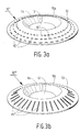
- Figs. 3a and 3b show two further embodiments of the friction increasing means according to the invention.
- the friction increasing means consist of upright edges 15', analogously to the embodiment of Fig. 2a, which upright edges are arranged in the form of concentric rings on the elastic disc-shaped element 10'.
- said upright concentric ring edges 15' are interrupted.
- the elastic disc-shaped element 10" is provided with friction increasing means 15'', which are embodied as upright edges extending in radial direction.
- the chain segments of the snow chain 5 can be tensioned over the upright edges, thus providing pressure points that guarantee an adequate confinement and fixation of the elastic disc-shaped element 10 between the wheel 2 and the snow chain 5.
- the chain segments may be confined between two edge portions, so that the chain segments "hook" behind the upright edges of the friction increasing means 15''.
- Figs. 4 and 5a-5b show a snow chain 5 fitted round a tyre 4 and a wheel 2 of the vehicle, with an embodiment of the elastic disc-shaped element 10 according to the invention fitted therebetween.
- Fig. 4 shows a snow chain 5 and the elastic disc-shaped element 10, seen from one side of the vehicle 1, whilst Figs. of 5a-5b show the vehicle 1 provided with the snow chain 5 and the elastic disc-shaped element 10 more from the front side.
- Figs. 4, 5a and 5b clearly show the recessed portion 12 as well as the friction increasing means 15, which are embodied as concentric upright edges 15, analogously to Fig. 2a.
- Fig. 4 clearly shows that the diameter of the elastic disc-shaped element 10 is larger than the diameter of the wheel 2 but smaller than the diameter of the tyre 4. All chain segments of the snow chain 5 are thus fitted over the elastic disc-shaped element 10, so that they will not come into contact with the wheel 2 while the vehicle 1 is driving.
- the elastic disc-shaped element 10 is provided with an opening 16, which is located precisely in the centre in this embodiment.
- the opening 16 makes it easier for the user to handle the elastic disc-shaped element 10. More in particular, the opening 16 functions to make it possible to take hold of the elastic disc-shaped element and correctly position (read: centre) the elastic disc-shaped element 10 with respect to the wheel 2 and the tyre 4 upon fitting of the snow chain 5.
- the elastic disc-shaped element 10 is provided with several openings 17 in Fig. 4, which openings are intended for draining water that may undesirably collect between the elastic disc-shaped element 10 and the wheel 2 / tyre 4.
- the openings 17 also function to allow air to flow through while driving, thus preventing movement/flapping of the elastic disc-shaped element 10 and thus displacement thereof. In addition to that, the handling/road-holding of the vehicle 1 is not interfered with in this manner.
- Fig. 5a and more in particular Fig. 5b clearly shows, the external dimensions of the vehicle 1 only increase to a minor extent when the elastic disc-shaped element 10 is fitted between the wheel 2 and the snow chain 5. Thus, the aerodynamics and the road-holding of the vehicle 1 are not adversely affected.
- the elastic disc-shaped element 10 is made of a plastic in all the illustrated embodiments, which in the first place results in a product which is light in weight, so that the handling and the road-holding of the vehicle 1 will not be adversely affected while driving. More in particular, a thermoplastic is to be used as said plastic, which makes it possible to manufacture of the elastic disc-shaped element in any shape thereof by means of a heating and pressing process.
- this material is very easy to work, for example by means of a cutting operation, so that it is possible to obtain the elastic disc-shaped element in the desired diameter and (optionally) provided with the desired openings 16-17 in one operation.
- the recessed portion 12 with the obliquely extending transition 14 on the one hand and the friction increasing means 15 in the form of (concentric or radial, interrupted or uninterrupted) upright edges on the other hand can then be formed in the elastic disc-shaped element 10 by subsequently heating the thermoplastic and shaping it in a mould makes.
- the heating and the pressing step can be carried out in succession; a quicker a manufacturing method can be obtained, however, by additionally deforming the elastic disc-shaped element 10 to the desired shape, for example as shown in Figs. 2a and 2b, during the heating step in the pressing mould.
- the friction increasing means 15 may also be embodied as upright, circular areas, which may be formed on the elastic disc-shaped element 10 in the form of a line (concentric ring) or in any other form.
- the elastic disc-shaped element 10 is provided with only one openings 16 in figures 4, 5a and 5b, the element may also comprise two, three or more openings positioned round the centre of the elastic disc-shaped element 10, into which openings the user can put his fingers. This makes it easier to handle the elastic disc-shaped element upon fitting thereof.
- the elastic disc-shaped element 10 is also very suitable as a protective cover against spurting grit, which is used as a traction-increasing material in many winter sports countries (instead of salt) to prevent against roads becoming slippery due to snow or ice.
- the elastic disc-shaped element 10 is very easy to clean and, in addition, is moisture and frost-resistant.
Landscapes
- Engineering & Computer Science (AREA)
- Mechanical Engineering (AREA)
- Cleaning Of Streets, Tracks, Or Beaches (AREA)
- Tires In General (AREA)
- Gears, Cams (AREA)
Applications Claiming Priority (2)
| Application Number | Priority Date | Filing Date | Title |
|---|---|---|---|
| NL1024570 | 2003-10-20 | ||
| NL1024570A NL1024570C2 (nl) | 2003-10-20 | 2003-10-20 | Sneeuwketting alsmede onderdeel hiervoor. |
Publications (1)
| Publication Number | Publication Date |
|---|---|
| EP1526008A1 true EP1526008A1 (fr) | 2005-04-27 |
Family
ID=34386859
Family Applications (2)
| Application Number | Title | Priority Date | Filing Date |
|---|---|---|---|
| EP04075206A Withdrawn EP1526007A1 (fr) | 2003-10-20 | 2004-01-28 | Chaíne à neige, pièce pour celle-ci et méthode pour placer une telle chaíne à neige |
| EP04077878A Withdrawn EP1526008A1 (fr) | 2003-10-20 | 2004-10-20 | Chaíne à neige, pièce pour celle-ci et méthode pour placer une telle chaíne à neige |
Family Applications Before (1)
| Application Number | Title | Priority Date | Filing Date |
|---|---|---|---|
| EP04075206A Withdrawn EP1526007A1 (fr) | 2003-10-20 | 2004-01-28 | Chaíne à neige, pièce pour celle-ci et méthode pour placer une telle chaíne à neige |
Country Status (2)
| Country | Link |
|---|---|
| EP (2) | EP1526007A1 (fr) |
| NL (1) | NL1024570C2 (fr) |
Cited By (1)
| Publication number | Priority date | Publication date | Assignee | Title |
|---|---|---|---|---|
| EP2008838A1 (fr) * | 2007-06-28 | 2008-12-31 | Thule S.p.A. | Dispositif anti-rayures de jante de roue pour chaînes de neige |
Citations (3)
| Publication number | Priority date | Publication date | Assignee | Title |
|---|---|---|---|---|
| DE4225802A1 (de) | 1992-07-31 | 1994-02-03 | Rud Ketten Rieger & Dietz | Felgenschutz für mit Gleitschutzketten zu versehende Fahrzeugräder |
| US6446690B1 (en) | 1998-03-20 | 2002-09-10 | Rud-Kettenfabrik Rieger & Dietz Gmbh U. Co. | Antislipping device |
| NL1023069C1 (nl) * | 2003-04-01 | 2004-10-04 | Guido Andre Magdalena Va Acker | Schijf ter bescherming van de autovelgen bij gebruik van sneeuwkettingen. |
-
2003
- 2003-10-20 NL NL1024570A patent/NL1024570C2/nl not_active IP Right Cessation
-
2004
- 2004-01-28 EP EP04075206A patent/EP1526007A1/fr not_active Withdrawn
- 2004-10-20 EP EP04077878A patent/EP1526008A1/fr not_active Withdrawn
Patent Citations (3)
| Publication number | Priority date | Publication date | Assignee | Title |
|---|---|---|---|---|
| DE4225802A1 (de) | 1992-07-31 | 1994-02-03 | Rud Ketten Rieger & Dietz | Felgenschutz für mit Gleitschutzketten zu versehende Fahrzeugräder |
| US6446690B1 (en) | 1998-03-20 | 2002-09-10 | Rud-Kettenfabrik Rieger & Dietz Gmbh U. Co. | Antislipping device |
| NL1023069C1 (nl) * | 2003-04-01 | 2004-10-04 | Guido Andre Magdalena Va Acker | Schijf ter bescherming van de autovelgen bij gebruik van sneeuwkettingen. |
Cited By (2)
| Publication number | Priority date | Publication date | Assignee | Title |
|---|---|---|---|---|
| EP2008838A1 (fr) * | 2007-06-28 | 2008-12-31 | Thule S.p.A. | Dispositif anti-rayures de jante de roue pour chaînes de neige |
| JP2009006998A (ja) * | 2007-06-28 | 2009-01-15 | Thule Spa | スノーチェーン用のホイールリムのアンチスクラッチ装置 |
Also Published As
| Publication number | Publication date |
|---|---|
| NL1024570C2 (nl) | 2005-04-22 |
| EP1526007A1 (fr) | 2005-04-27 |
Similar Documents
| Publication | Publication Date | Title |
|---|---|---|
| EP2150421B8 (fr) | Protecteur de jante | |
| EP2349740B1 (fr) | Dispositif de protection pour roue de véhicule | |
| RU2616479C2 (ru) | Шина с ламинированным слоем | |
| US4319618A (en) | Pneumatic tire wheel for use in off-road vehicles | |
| US5624509A (en) | Wheel traction device | |
| JP3307398B2 (ja) | 環状装置を有する自動車用ホイール | |
| EP3829895A1 (fr) | Systeme de protection laterale pour jantes de vehicules automobiles | |
| US5076335A (en) | Antiskid device having rotatable crossbands | |
| EP1957292B1 (fr) | Dispositif de protection de roue en alliage | |
| EP1526008A1 (fr) | Chaíne à neige, pièce pour celle-ci et méthode pour placer une telle chaíne à neige | |
| KR101678339B1 (ko) | 스노우 타이어 커버 및 그 장착방법 | |
| EP2158097B1 (fr) | Pneu pourvu d'un dispositif deviateur de projections | |
| US20090025845A1 (en) | Antiskid device for vehicles | |
| WO2001043958A1 (fr) | Element de recouvrement et son procede de fabrication | |
| JPH02220902A (ja) | スノータイヤ用ブレーキピン及びスノータイヤ | |
| CN211000791U (zh) | 一种通用型防滑布套 | |
| CA2395168A1 (fr) | Chenille montee sur pneus | |
| JPS5873409A (ja) | 自動車用スリツプ防止具 | |
| KR100566922B1 (ko) | 타이어 장착용 미끄럼 방지구 | |
| JP2602825Y2 (ja) | タイヤチェーン | |
| US1195640A (en) | Dsta spa | |
| KR100572375B1 (ko) | 타이어 장착용 미끄럼 방지구 | |
| CN2326460Y (zh) | 防滑轮胎 | |
| JPH0444403Y2 (fr) | ||
| KR930006322Y1 (ko) | 스파이크 타이어 |
Legal Events
| Date | Code | Title | Description |
|---|---|---|---|
| PUAI | Public reference made under article 153(3) epc to a published international application that has entered the european phase |
Free format text: ORIGINAL CODE: 0009012 |
|
| AK | Designated contracting states |
Kind code of ref document: A1 Designated state(s): AT BE BG CH CY CZ DE DK EE ES FI FR GB GR HU IE IT LI LU MC NL PL PT RO SE SI SK TR |
|
| AX | Request for extension of the european patent |
Extension state: AL HR LT LV MK |
|
| 17P | Request for examination filed |
Effective date: 20051020 |
|
| AKX | Designation fees paid |
Designated state(s): AT BE BG CH CY CZ DE DK EE ES FI FR GB GR HU IE IT LI LU MC NL PL PT RO SE SI SK TR |
|
| STAA | Information on the status of an ep patent application or granted ep patent |
Free format text: STATUS: THE APPLICATION IS DEEMED TO BE WITHDRAWN |
|
| 18D | Application deemed to be withdrawn |
Effective date: 20090501 |