EP1533884A1 - Accumulateur d'énergie cinétique - Google Patents
Accumulateur d'énergie cinétique Download PDFInfo
- Publication number
- EP1533884A1 EP1533884A1 EP04078058A EP04078058A EP1533884A1 EP 1533884 A1 EP1533884 A1 EP 1533884A1 EP 04078058 A EP04078058 A EP 04078058A EP 04078058 A EP04078058 A EP 04078058A EP 1533884 A1 EP1533884 A1 EP 1533884A1
- Authority
- EP
- European Patent Office
- Prior art keywords
- kinetic energy
- rotor
- energy accumulator
- coils
- drum
- Prior art date
- Legal status (The legal status is an assumption and is not a legal conclusion. Google has not performed a legal analysis and makes no representation as to the accuracy of the status listed.)
- Granted
Links
- 238000004146 energy storage Methods 0.000 title 1
- 210000000078 claw Anatomy 0.000 claims abstract description 15
- 239000004020 conductor Substances 0.000 claims abstract description 11
- 230000005611 electricity Effects 0.000 claims abstract description 11
- 230000001360 synchronised effect Effects 0.000 claims description 11
- 229910000831 Steel Inorganic materials 0.000 claims description 3
- 239000010959 steel Substances 0.000 claims description 3
- 241001417494 Sciaenidae Species 0.000 description 3
- 230000008878 coupling Effects 0.000 description 2
- 238000010168 coupling process Methods 0.000 description 2
- 238000005859 coupling reaction Methods 0.000 description 2
- 238000011084 recovery Methods 0.000 description 2
- 238000004804 winding Methods 0.000 description 2
- 230000001133 acceleration Effects 0.000 description 1
- 238000001816 cooling Methods 0.000 description 1
- 230000037213 diet Effects 0.000 description 1
- 235000005911 diet Nutrition 0.000 description 1
- 230000005284 excitation Effects 0.000 description 1
- 238000005461 lubrication Methods 0.000 description 1
- 238000004519 manufacturing process Methods 0.000 description 1
- 239000002184 metal Substances 0.000 description 1
Images



Classifications
-
- H—ELECTRICITY
- H02—GENERATION; CONVERSION OR DISTRIBUTION OF ELECTRIC POWER
- H02K—DYNAMO-ELECTRIC MACHINES
- H02K49/00—Dynamo-electric clutches; Dynamo-electric brakes
- H02K49/02—Dynamo-electric clutches; Dynamo-electric brakes of the asynchronous induction type
- H02K49/04—Dynamo-electric clutches; Dynamo-electric brakes of the asynchronous induction type of the eddy-current hysteresis type
- H02K49/043—Dynamo-electric clutches; Dynamo-electric brakes of the asynchronous induction type of the eddy-current hysteresis type with a radial airgap
-
- H—ELECTRICITY
- H02—GENERATION; CONVERSION OR DISTRIBUTION OF ELECTRIC POWER
- H02K—DYNAMO-ELECTRIC MACHINES
- H02K17/00—Asynchronous induction motors; Asynchronous induction generators
- H02K17/02—Asynchronous induction motors
- H02K17/16—Asynchronous induction motors having rotors with internally short-circuited windings, e.g. cage rotors
-
- H—ELECTRICITY
- H02—GENERATION; CONVERSION OR DISTRIBUTION OF ELECTRIC POWER
- H02K—DYNAMO-ELECTRIC MACHINES
- H02K7/00—Arrangements for handling mechanical energy structurally associated with dynamo-electric machines, e.g. structural association with mechanical driving motors or auxiliary dynamo-electric machines
- H02K7/02—Additional mass for increasing inertia, e.g. flywheels
- H02K7/025—Additional mass for increasing inertia, e.g. flywheels for power storage
-
- H—ELECTRICITY
- H02—GENERATION; CONVERSION OR DISTRIBUTION OF ELECTRIC POWER
- H02K—DYNAMO-ELECTRIC MACHINES
- H02K11/00—Structural association of dynamo-electric machines with electric components or with devices for shielding, monitoring or protection
- H02K11/04—Structural association of dynamo-electric machines with electric components or with devices for shielding, monitoring or protection for rectification
- H02K11/042—Rectifiers associated with rotating parts, e.g. rotor cores or rotary shafts
-
- Y—GENERAL TAGGING OF NEW TECHNOLOGICAL DEVELOPMENTS; GENERAL TAGGING OF CROSS-SECTIONAL TECHNOLOGIES SPANNING OVER SEVERAL SECTIONS OF THE IPC; TECHNICAL SUBJECTS COVERED BY FORMER USPC CROSS-REFERENCE ART COLLECTIONS [XRACs] AND DIGESTS
- Y02—TECHNOLOGIES OR APPLICATIONS FOR MITIGATION OR ADAPTATION AGAINST CLIMATE CHANGE
- Y02E—REDUCTION OF GREENHOUSE GAS [GHG] EMISSIONS, RELATED TO ENERGY GENERATION, TRANSMISSION OR DISTRIBUTION
- Y02E60/00—Enabling technologies; Technologies with a potential or indirect contribution to GHG emissions mitigation
- Y02E60/16—Mechanical energy storage, e.g. flywheels or pressurised fluids
Definitions
- This invention relates to an energy accumulator kinetic, more precisely, a large accumulator reserve of kinetic energy.
- ASIs are primarily intended to safeguard users susceptible to disturbances of a network electrical, that is, users as per example of intensive care units in hospitals or highly computerized service companies, for which an interruption of the electrical network during a few milliseconds endangers human lives or causes significant financial costs.
- UPS power accumulators
- the kinetic energy reserve is realizes by means of a cylinder full in rotation.
- a disadvantage of this type of energy accumulator is that the cylinder has a low moment of inertia which must be compensated by a fast rotational speed because the energy accumulated kinetics in the cylinder is proportional with the square of the speed of rotation.
- Another type of known kinetic energy accumulator is equipped with a rotating steel drum in which the kinetic energy is accumulated.
- the rotating drum is indirectly linked to a synchronous generator that allows convert accumulated kinetic energy into electricity.
- a disadvantage of this type of accumulators is that, if you want to make an energy accumulator that, with the same weight and bulk, achieves double the capacity of known systems, a diameter must be used large drum interior. Such a large diameter is incompatible with the use of a winding rotor in this case, the mechanical stress Centrifugal forces of the rotor become difficult surmountable.
- An advantage of an accumulator according to the invention is that claw rotor is applied in order to couple electromagnetic the shaft with the drum in which the kinetic energy is stored.
- This claw rotor requires excitation power reduced by a factor of 2 to 4 compared to a rotor with a same power applied in a known type of accumulator, which allows the use of a weak exciter weight and bulk.
- An advantage, related to the application of an asynchronous motor drum drive which is made up of the ring Gram of short length, is that one can realize a kinetic energy accumulator with a bulk relatively short.
- An advantage of the previous advantage is that an UPS realized with the energy accumulator according to the invention is relatively compact and therefore occupies only a minimum of square.
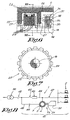
- FIG. 1 schematically shows a network electricity supply 1, supplying energy to sensitive users 2, equipped with a power system uninterrupted power supply, in short, an UPS 3.
- the UPS which is shown in Figure 2, consists of mainly a synchronous machine 4 and a kinetic energy accumulator 5 according to the invention, which are mounted in a carcass 6.
- the synchronous machine 4 is, in known manner, constituted of a shaft 7 being supported by a bearing 8 and carrying a main rotor 9 provided with coils 10.
- a main stator 11, surrounding the aforementioned rotor 9, is mounted in the carcass 6 and is also provided with coils 12.
- an exciter rotor 13, provided of coils 14, is fixed on the above-mentioned shaft 7, this rotor exciter 13 being surrounded by an exciter stator 15 which is provided with coils 16.
- the synchronous machine 4 then contains a fan 17 cooling that can provide a rotor airing 9 main and main stator 11.
- the kinetic energy accumulator 5 comprises a shaft 18 rigidly connected to the shaft 7 of the synchronous machine 4, and carried by the bearings 19 and 20.
- the shaft 18 also bears a flywheel 21.
- FIG. 5 a rotor 22 with claws 23 being fixed on the aforesaid tree 18, which constitutes the part, called the "fixed" part of an electromagnetic coupler and which is provided with coils 24.
- the rotor 22 with claws 23 consists, in this case, of four parallel trays which at their ends are provided with claws 23.
- the other part of the above coupler consists of a steel drum 26 which is carried by bearings 27 and which can be driven in relative rotation with respect to the shaft 18 of the kinetic energy accumulator 5.
- a Gram 28 ring well known to those skilled in the art is fixed on the central bearing 19 of the carcass 6, surrounding the aforementioned tree 18 and being surrounded by the end of the drum 26.
- This gram ring 28 shown in detail in FIG. 3 consists of a set of magnetic sheets stacked 29 forming a circular laminated core, which is provided with longitudinal notches 31, in which coils 30 are wrapped around the core.
- the kinetic energy accumulator 5 is provided with a rotor exciter 32 with coils 33, which are related to coils 24 of the rotor 22 with claws 23 using conductors 34, which pass through a rectifying bridge 35 rotating well known.
- UPS 3 with an energy accumulator kinetics 5 is simple and is described below.
- a network 38 and a motor 39 preferably a diesel engine, driving a alternator 40.
- the network 38 and the aforementioned alternator 40 are connected to the local network 41 of the users 2, represented as examples by computers, using two circuit breakers 42-43.
- the local network 41 consists of a driver 44 connecting the energy sources, in this case the network 38 and the motor 39, to the users 2, which driver 44 is equipped with a self 45.
- this conductor 44 is provided with a first circuit breaker 46, while between the self 45 and the sensitive users 2, the conductor 44 is coupled to synchronous machine 4 of ASI 3.
- conductor 44 Downstream of this coupling, conductor 44 is provided with a second circuit breaker 47, which isolates the UPS 3 users 2.
- a conductor 48 couples the coils 30 of the ring Gram 28 with energy sources 38-39, which driver is equipped with a circuit breaker 49.
- the coils 30 of the gram ring 28 are fed via the circuit breaker 49 by alternating currents coming from the network 38 with a frequency of, for example, 50 or 60 Hz (Hertz).
- the AC supplied to coils 37 of stator 36 above can be replaced by a direct current.
- this network 38 is disconnected from the local network 41 by opening the circuit breaker 46 as well as the opening of the circuit breaker 49.
- the synchronous machine 4 becomes instantaneously alternator supplying the energy absorbed by the users 2. This energy comes from the recovery of the kinetic energy stored in the drum 26 in rotation.
- This recovery is achieved by modulating the current continuous injected into the coils 37 of the stator 36 of the exciter of the kinetic energy accumulator 5.
- the drum 26 now serves as an armature in which are generated eddy currents that allow the rotor 22 with claws 23 to drive the shaft 7 of the machine synchronous 4 at a desired speed.
- the engine 39 is started by training the alternator 40 and accelerates to its speed. Once this speed is reached, the diet of the local network 41 is done by the energy generated by the alternator 40 driven by the engine 39 by closing circuit breakers 43 and 46 after synchronization.
- the drum 26, which has lost some of its energy, is again accelerated by feeding the Gramme ring 28 electrical current from the alternator 40.
- short-circuit rings 50 in conductive materials can be introduced into ends of the drum 26 surrounding the gram ring 28.
- Figures 6 and 7 show a variant of which the trays 25 of the claw rotor 22 are made in the form of four crenelated plates 25 between which the coils 24 are inserted.
- FIGS. 8 and 9 Another variant is shown in FIGS. 8 and 9 and is achieved by linking the axis of a heat engine 39 with the shaft 7 and 18 of the UPS 3 using a clutch 51.
- the energy generated by the motor 39 is not converted into electricity by an alternator 40 but by the synchronous machine 4.
Landscapes
- Engineering & Computer Science (AREA)
- Power Engineering (AREA)
- Connection Of Motors, Electrical Generators, Mechanical Devices, And The Like (AREA)
- Saccharide Compounds (AREA)
- Synchronous Machinery (AREA)
- Transition And Organic Metals Composition Catalysts For Addition Polymerization (AREA)
Abstract
Description
- un arbre qui porte un rotor muni de bobines et un rotor d'excitatrice avec bobines,
- un tambour entourant le rotor susdit, lequel tambour comporte des paliers lui permettant de tourner librement autour de l'arbre susdit,
- une carcasse portant l'arbre susdit, et le stator de l'excitatrice mentionnée ci-dessus,
- le rotor susdit est un rotor à griffes, muni de bobines qui sont connectées aux bobines du rotor de l'excitatrice, au travers d'un pont redresseur,
- il comprend un anneau Gramme comportant des bobines, l'anneau Gramme (28) étant entouré par le tambour, et étant connecté à une source d'électricité.
Claims (11)
- Accumulateur d'énergie cinétique comprenant essentiellement :caractérisé en ce que :un arbre qui porte un rotor muni de bobines et un rotor d'excitatrice bobiné,un tambour entourant le rotor susdit, lequel tambour comporte des paliers lui permettant de tourner librement autour de l'arbre susdit,une carcasse portant l'arbre susdit, et le stator de l'excitatrice mentionnée ci-dessus,le rotor (22) susdit est un rotor à griffes (23), muni de bobines (24) qui sont connectées par un conducteur (34) aux bobines (33) du rotor de l'excitatrice (32), au travers d'un pont redresseur (35).il comprend un anneau Gramme (28) comportant des bobines (30), l'anneau Gramme (28) étant entouré par le tambour (26) et étant connecté au moyen d'un conducteur (48) à une source d'électricité (38-39).
- Accumulateur d'énergie cinétique selon la revendication 1, caractérisé en ce qu'il est lié à une machine synchrone pour former une ASI( ( Alimentation Sans Interruption) de grande autonomie.
- Accumulateur d'énergie cinétique selon la revendication 1, caractérisé en ce qu'il est lié à une machine synchrone pour former une ASI( Alimentation Sans Interruption) de grande puissance.
- Accumulateur d'énergie cinétique selon l'une quelconque des revendications précédentes, caractérisé en ce que les bobines (37) du stator (36) de l'excitatrice susdites peuvent être reliées à une source d'électricité alternative et/ou à une source d'électricité continue.
- Accumulateur d'énergie cinétique selon l'une quelconque des revendications précédentes, caractérisé en ce que la source d'électricité reliée à l'anneau Gramme (28) est un réseau (38) électrique et/ou une alimentation à fréquence variable.
- Accumulateur d'énergie cinétique selon l'une quelconque des revendications précédentes, caractérisé en ce que la partie du tambour (26) entourant l'anneau Gramme(28) est muni des anneaux court-circuit (50) en matériaux conducteurs.
- Accumulateur d'énergie cinétique selon l'une des revendications 2 ou 3, caractérisé en ce que l'arbre (18) de l'accumulateur d'énergie cinétique est lié à l'axe d'un moteur (39).
- Accumulateur d'énergie cinétique selon la revendication 7, caractérisé en ce que la liaison entre l'arbre (18) susdit et l'axe du moteur (39) est réalisée au moyen d'un embrayage (51).
- Accumulateur d'énergie cinétique selon revendication 1, caractérisé en ce que le tambour (26) est réalisé en acier.
- Accumulateur d'énergie cinétique selon la revendication 1, caractérisé en ce que le rotor (22) à griffes (23) est constitué de plusieurs plateaux (25) parallèles qui, à leurs extrémités, sont pourvus de griffes (23).
- Accumulateur d'énergie cinétique selon la revendication 1, caractérisé en ce que le rotor (22) à griffes (23) est constitué de plusieurs plateaux (25) parallèles crénelés, entre lesquels les bobines (24) sont insérées.
Applications Claiming Priority (2)
| Application Number | Priority Date | Filing Date | Title |
|---|---|---|---|
| BE2003/0622A BE1015793A3 (fr) | 2003-11-19 | 2003-11-19 | |
| BE200300622 | 2003-11-19 |
Publications (2)
| Publication Number | Publication Date |
|---|---|
| EP1533884A1 true EP1533884A1 (fr) | 2005-05-25 |
| EP1533884B1 EP1533884B1 (fr) | 2006-10-18 |
Family
ID=34427389
Family Applications (1)
| Application Number | Title | Priority Date | Filing Date |
|---|---|---|---|
| EP04078058A Expired - Lifetime EP1533884B1 (fr) | 2003-11-19 | 2004-11-08 | Accumulateur d'énergie cinétique |
Country Status (7)
| Country | Link |
|---|---|
| EP (1) | EP1533884B1 (fr) |
| AT (1) | ATE343241T1 (fr) |
| BE (1) | BE1015793A3 (fr) |
| CA (1) | CA2485316C (fr) |
| DE (1) | DE602004002830T2 (fr) |
| ES (1) | ES2275174T3 (fr) |
| PT (1) | PT1533884E (fr) |
Cited By (8)
| Publication number | Priority date | Publication date | Assignee | Title |
|---|---|---|---|---|
| EP2239830A1 (fr) * | 2009-04-06 | 2010-10-13 | KS Research, société anonyme | Moteur électrique à induction à courant alternatif |
| AT514240A1 (de) * | 2013-04-22 | 2014-11-15 | Hitzinger Gmbh | Energiespeicher und Vorrichtung zur unterbrechungsfreien Energieversorgung |
| EP2945263A2 (fr) | 2014-05-16 | 2015-11-18 | KS RESEARCH, société anonyme | Système d'alimentation électrique sans coupure |
| US20160372991A1 (en) * | 2015-06-16 | 2016-12-22 | Audi Ag | Energy transmission device |
| WO2019049102A1 (fr) | 2017-09-11 | 2019-03-14 | Ks Research, Société Anonyme | Systeme de protection pour limiter l'impact des perturbations d'un reseau electrique externe sur le reseau local d'un site branche sur le reseau externe |
| BE1026573B1 (fr) * | 2018-08-28 | 2020-03-30 | Euro Diesel S A | Procédé d’alimentation d’un appareil électrique en courant électrique continu et accumulateur d’énergie électrique |
| WO2020095149A1 (fr) * | 2018-11-08 | 2020-05-14 | Ks Research, Société Anonyme | Machine d'alimentation sans interruption |
| BE1026772A1 (fr) | 2018-11-08 | 2020-06-05 | Ks Research Sa | Machine ASI (Alimentation Sans Interruption) |
Citations (5)
| Publication number | Priority date | Publication date | Assignee | Title |
|---|---|---|---|---|
| GB705559A (en) * | 1951-12-29 | 1954-03-17 | Dynamatic Corp | Improvements in eddy-current couplings, brakes and dynamometers |
| GB1324265A (en) * | 1970-02-05 | 1973-07-25 | Bosch Gmbh Robert | Eddy current brake |
| US6023152A (en) * | 1997-04-14 | 2000-02-08 | Piller-Gmbh | System for stabilizing a power supply system |
| US20020167234A1 (en) * | 2001-04-18 | 2002-11-14 | Otto Farkas | Standby power system |
| US20030137196A1 (en) * | 2002-01-24 | 2003-07-24 | Abraham Liran | Power supply for providing continuous and regulated energy to the power user |
-
2003
- 2003-11-19 BE BE2003/0622A patent/BE1015793A3/fr not_active IP Right Cessation
-
2004
- 2004-11-08 AT AT04078058T patent/ATE343241T1/de active
- 2004-11-08 DE DE602004002830T patent/DE602004002830T2/de not_active Expired - Lifetime
- 2004-11-08 ES ES04078058T patent/ES2275174T3/es not_active Expired - Lifetime
- 2004-11-08 EP EP04078058A patent/EP1533884B1/fr not_active Expired - Lifetime
- 2004-11-08 PT PT04078058T patent/PT1533884E/pt unknown
- 2004-11-17 CA CA2485316A patent/CA2485316C/fr not_active Expired - Fee Related
Patent Citations (5)
| Publication number | Priority date | Publication date | Assignee | Title |
|---|---|---|---|---|
| GB705559A (en) * | 1951-12-29 | 1954-03-17 | Dynamatic Corp | Improvements in eddy-current couplings, brakes and dynamometers |
| GB1324265A (en) * | 1970-02-05 | 1973-07-25 | Bosch Gmbh Robert | Eddy current brake |
| US6023152A (en) * | 1997-04-14 | 2000-02-08 | Piller-Gmbh | System for stabilizing a power supply system |
| US20020167234A1 (en) * | 2001-04-18 | 2002-11-14 | Otto Farkas | Standby power system |
| US20030137196A1 (en) * | 2002-01-24 | 2003-07-24 | Abraham Liran | Power supply for providing continuous and regulated energy to the power user |
Cited By (20)
| Publication number | Priority date | Publication date | Assignee | Title |
|---|---|---|---|---|
| EP2239830A1 (fr) * | 2009-04-06 | 2010-10-13 | KS Research, société anonyme | Moteur électrique à induction à courant alternatif |
| BE1018519A5 (fr) * | 2009-04-06 | 2011-02-01 | Ks Res Sociutu Anonyme | Moteur electrique a induction a courant alternatif. |
| US8878412B2 (en) | 2009-04-06 | 2014-11-04 | Ks Research S.A. | Alternating current electric induction motor with auxiliary closed loop toroidal winding |
| AT514240A1 (de) * | 2013-04-22 | 2014-11-15 | Hitzinger Gmbh | Energiespeicher und Vorrichtung zur unterbrechungsfreien Energieversorgung |
| EP2945263A2 (fr) | 2014-05-16 | 2015-11-18 | KS RESEARCH, société anonyme | Système d'alimentation électrique sans coupure |
| BE1022140B1 (fr) * | 2014-05-16 | 2016-02-19 | KS RESEARCH société anonyme | Systeme d'alimentation electrique sans coupure |
| EP2945263A3 (fr) * | 2014-05-16 | 2016-03-16 | KS RESEARCH, société anonyme | Système d'alimentation électrique sans coupure |
| US9906075B2 (en) | 2014-05-16 | 2018-02-27 | Ks Research Sa | Uninterruptible power supply system |
| US20160372991A1 (en) * | 2015-06-16 | 2016-12-22 | Audi Ag | Energy transmission device |
| BE1025533B1 (fr) * | 2017-09-11 | 2019-04-08 | KS RESEARCH société anonyme | Système de protection pour limiter l'impact des perturbations d'un réseau électrique externe sur le réseau local d'un site branché sur le réseau externe |
| WO2019049102A1 (fr) | 2017-09-11 | 2019-03-14 | Ks Research, Société Anonyme | Systeme de protection pour limiter l'impact des perturbations d'un reseau electrique externe sur le reseau local d'un site branche sur le reseau externe |
| US11594890B2 (en) | 2017-09-11 | 2023-02-28 | Ks Research, Société Anonyme | Protection system for limiting an impact of disruptions of an external electrical network on a local network |
| BE1026573B1 (fr) * | 2018-08-28 | 2020-03-30 | Euro Diesel S A | Procédé d’alimentation d’un appareil électrique en courant électrique continu et accumulateur d’énergie électrique |
| WO2020095149A1 (fr) * | 2018-11-08 | 2020-05-14 | Ks Research, Société Anonyme | Machine d'alimentation sans interruption |
| BE1026772A1 (fr) | 2018-11-08 | 2020-06-05 | Ks Research Sa | Machine ASI (Alimentation Sans Interruption) |
| BE1026773A1 (fr) | 2018-11-08 | 2020-06-05 | Ks Research Sa | Machine ASI (Alimentation Sans Interruption) |
| BE1026773B1 (fr) * | 2018-11-08 | 2020-06-08 | Ks Research Sa | Machine ASI (Alimentation Sans Interruption) |
| BE1026772B1 (fr) * | 2018-11-08 | 2020-06-09 | Ks Research Sa | Machine ASI (Alimentation Sans Interruption) |
| US20220085647A1 (en) * | 2018-11-08 | 2022-03-17 | KS RESEARCH société anonyme | Uninterruptible-power-supply machine |
| US11652363B2 (en) * | 2018-11-08 | 2023-05-16 | KS RESEARCH société anonyme | Uninterruptible-power-supply machine |
Also Published As
| Publication number | Publication date |
|---|---|
| ES2275174T3 (es) | 2007-06-01 |
| PT1533884E (pt) | 2007-01-31 |
| EP1533884B1 (fr) | 2006-10-18 |
| CA2485316A1 (fr) | 2005-05-19 |
| BE1015793A3 (fr) | 2005-09-06 |
| ATE343241T1 (de) | 2006-11-15 |
| HK1079347A1 (en) | 2006-03-31 |
| CA2485316C (fr) | 2010-07-20 |
| DE602004002830T2 (de) | 2007-06-14 |
| DE602004002830D1 (de) | 2006-11-30 |
Similar Documents
| Publication | Publication Date | Title |
|---|---|---|
| EP2688184A1 (fr) | Machine électrique réversible pour aéronef | |
| FR2952130A1 (fr) | Demarreur-generateur de turbomachine et procede pour sa commande. | |
| CA2485316C (fr) | Accumulateur d'energie cinetique | |
| FR2838576A1 (fr) | Procede de commande d'une machine electrique tournante polyphasee et reversible associee a un moteur thermique d'un vehicule automobile et agencement pour la mise en oeuvre de ce procede | |
| FR3042659A1 (fr) | Demarreur-generateur de turbomachine a machine electrique asynchrone multi-enroulements | |
| CA2873933C (fr) | Systeme d'alimentation en energie electrique comprenant une machine asynchrone et moteur de propulsion equipe d'un tel systeme d'alimentation en energie electrique | |
| EP2582576A1 (fr) | Alimentation electrique des equipements portes par le rotor d'un moteur d'aeronef | |
| FR2982441A1 (fr) | Machine synchrone hybride. | |
| FR2881896A1 (fr) | Systeme de generation electrique a frequence fixe a coupleur a induction et utilisation de celui-ci dans un aeronef | |
| WO2020095149A1 (fr) | Machine d'alimentation sans interruption | |
| EP1235332B1 (fr) | Ensemble constitué par un ralentisseur électromagnétique et par ses moyens d'alimentations électrique | |
| EP2945263B1 (fr) | Système d'alimentation électrique sans coupure | |
| BE1005802A3 (fr) | Coupleur inductif. | |
| KR100663240B1 (ko) | 가속식 교류발전기를 갖는 운동 자전거 | |
| EP3878084B1 (fr) | Machine d'alimentation sans interruption | |
| CA2897891C (fr) | Dispositif electrique pour le stockage d'electricite par volant d'inertie | |
| EP0642209A1 (fr) | Dispositif de démarrage de turbine, notamment de turbine à gaz | |
| EP2239830A1 (fr) | Moteur électrique à induction à courant alternatif | |
| KR200399538Y1 (ko) | 가속식 교류발전기를 갖는 운동 자전거 | |
| FR3113211A1 (fr) | Générateur magnétique et système de génération électrique comprenant un tel générateur | |
| BE1026574B1 (fr) | Procédé d’alimentation d’un appareil électrique en courant électrique continu et accumulateur d’énergie électrique | |
| HK1079347B (en) | Kinetic energy storage | |
| FR2825845A1 (fr) | Machine dynamoelectrique pour vehicule | |
| FR2873870A1 (fr) | Procede et appareil pour supprimer le bruit electrique dans un ensemble rotor pour une machine electrique | |
| BE508596A (fr) |
Legal Events
| Date | Code | Title | Description |
|---|---|---|---|
| PUAI | Public reference made under article 153(3) epc to a published international application that has entered the european phase |
Free format text: ORIGINAL CODE: 0009012 |
|
| AK | Designated contracting states |
Kind code of ref document: A1 Designated state(s): AT BE BG CH CY CZ DE DK EE ES FI FR GB GR HU IE IS IT LI LU MC NL PL PT RO SE SI SK TR |
|
| AX | Request for extension of the european patent |
Extension state: AL HR LT LV MK YU |
|
| 17P | Request for examination filed |
Effective date: 20050707 |
|
| AKX | Designation fees paid |
Designated state(s): AT BE BG CH CY CZ DE DK EE ES FI FR GB GR HU IE IS IT LI LU MC NL PL PT RO SE SI SK TR |
|
| REG | Reference to a national code |
Ref country code: HK Ref legal event code: DE Ref document number: 1079347 Country of ref document: HK |
|
| GRAP | Despatch of communication of intention to grant a patent |
Free format text: ORIGINAL CODE: EPIDOSNIGR1 |
|
| GRAS | Grant fee paid |
Free format text: ORIGINAL CODE: EPIDOSNIGR3 |
|
| GRAA | (expected) grant |
Free format text: ORIGINAL CODE: 0009210 |
|
| AK | Designated contracting states |
Kind code of ref document: B1 Designated state(s): AT BE BG CH CY CZ DE DK EE ES FI FR GB GR HU IE IS IT LI LU MC NL PL PT RO SE SI SK TR |
|
| PG25 | Lapsed in a contracting state [announced via postgrant information from national office to epo] |
Ref country code: FI Free format text: LAPSE BECAUSE OF FAILURE TO SUBMIT A TRANSLATION OF THE DESCRIPTION OR TO PAY THE FEE WITHIN THE PRESCRIBED TIME-LIMIT Effective date: 20061018 Ref country code: SK Free format text: LAPSE BECAUSE OF FAILURE TO SUBMIT A TRANSLATION OF THE DESCRIPTION OR TO PAY THE FEE WITHIN THE PRESCRIBED TIME-LIMIT Effective date: 20061018 Ref country code: RO Free format text: LAPSE BECAUSE OF FAILURE TO SUBMIT A TRANSLATION OF THE DESCRIPTION OR TO PAY THE FEE WITHIN THE PRESCRIBED TIME-LIMIT Effective date: 20061018 Ref country code: SI Free format text: LAPSE BECAUSE OF FAILURE TO SUBMIT A TRANSLATION OF THE DESCRIPTION OR TO PAY THE FEE WITHIN THE PRESCRIBED TIME-LIMIT Effective date: 20061018 Ref country code: IE Free format text: LAPSE BECAUSE OF FAILURE TO SUBMIT A TRANSLATION OF THE DESCRIPTION OR TO PAY THE FEE WITHIN THE PRESCRIBED TIME-LIMIT Effective date: 20061018 Ref country code: PL Free format text: LAPSE BECAUSE OF FAILURE TO SUBMIT A TRANSLATION OF THE DESCRIPTION OR TO PAY THE FEE WITHIN THE PRESCRIBED TIME-LIMIT Effective date: 20061018 |
|
| REG | Reference to a national code |
Ref country code: GB Ref legal event code: FG4D Free format text: NOT ENGLISH |
|
| REG | Reference to a national code |
Ref country code: CH Ref legal event code: EP Ref country code: IE Ref legal event code: FG4D Free format text: LANGUAGE OF EP DOCUMENT: FRENCH |
|
| REF | Corresponds to: |
Ref document number: 602004002830 Country of ref document: DE Date of ref document: 20061130 Kind code of ref document: P |
|
| REG | Reference to a national code |
Ref country code: CH Ref legal event code: NV Representative=s name: MICHELI & CIE INGENIEURS-CONSEILS |
|
| PG25 | Lapsed in a contracting state [announced via postgrant information from national office to epo] |
Ref country code: DK Free format text: LAPSE BECAUSE OF FAILURE TO SUBMIT A TRANSLATION OF THE DESCRIPTION OR TO PAY THE FEE WITHIN THE PRESCRIBED TIME-LIMIT Effective date: 20070118 Ref country code: BG Free format text: LAPSE BECAUSE OF FAILURE TO SUBMIT A TRANSLATION OF THE DESCRIPTION OR TO PAY THE FEE WITHIN THE PRESCRIBED TIME-LIMIT Effective date: 20070118 |
|
| REG | Reference to a national code |
Ref country code: PT Ref legal event code: SC4A Free format text: AVAILABILITY OF NATIONAL TRANSLATION Effective date: 20070105 |
|
| REG | Reference to a national code |
Ref country code: SE Ref legal event code: TRGR |
|
| PG25 | Lapsed in a contracting state [announced via postgrant information from national office to epo] |
Ref country code: IS Free format text: LAPSE BECAUSE OF FAILURE TO SUBMIT A TRANSLATION OF THE DESCRIPTION OR TO PAY THE FEE WITHIN THE PRESCRIBED TIME-LIMIT Effective date: 20070218 |
|
| GBT | Gb: translation of ep patent filed (gb section 77(6)(a)/1977) |
Effective date: 20070125 |
|
| REG | Reference to a national code |
Ref country code: HU Ref legal event code: AG4A Ref document number: E001106 Country of ref document: HU |
|
| REG | Reference to a national code |
Ref country code: ES Ref legal event code: FG2A Ref document number: 2275174 Country of ref document: ES Kind code of ref document: T3 |
|
| REG | Reference to a national code |
Ref country code: IE Ref legal event code: FD4D |
|
| REG | Reference to a national code |
Ref country code: HK Ref legal event code: GR Ref document number: 1079347 Country of ref document: HK |
|
| PLBE | No opposition filed within time limit |
Free format text: ORIGINAL CODE: 0009261 |
|
| STAA | Information on the status of an ep patent application or granted ep patent |
Free format text: STATUS: NO OPPOSITION FILED WITHIN TIME LIMIT |
|
| 26N | No opposition filed |
Effective date: 20070719 |
|
| PG25 | Lapsed in a contracting state [announced via postgrant information from national office to epo] |
Ref country code: GR Free format text: LAPSE BECAUSE OF FAILURE TO SUBMIT A TRANSLATION OF THE DESCRIPTION OR TO PAY THE FEE WITHIN THE PRESCRIBED TIME-LIMIT Effective date: 20070119 |
|
| PG25 | Lapsed in a contracting state [announced via postgrant information from national office to epo] |
Ref country code: EE Free format text: LAPSE BECAUSE OF FAILURE TO SUBMIT A TRANSLATION OF THE DESCRIPTION OR TO PAY THE FEE WITHIN THE PRESCRIBED TIME-LIMIT Effective date: 20061018 |
|
| PG25 | Lapsed in a contracting state [announced via postgrant information from national office to epo] |
Ref country code: LU Free format text: LAPSE BECAUSE OF NON-PAYMENT OF DUE FEES Effective date: 20061108 Ref country code: TR Free format text: LAPSE BECAUSE OF FAILURE TO SUBMIT A TRANSLATION OF THE DESCRIPTION OR TO PAY THE FEE WITHIN THE PRESCRIBED TIME-LIMIT Effective date: 20061018 |
|
| PG25 | Lapsed in a contracting state [announced via postgrant information from national office to epo] |
Ref country code: CY Free format text: LAPSE BECAUSE OF FAILURE TO SUBMIT A TRANSLATION OF THE DESCRIPTION OR TO PAY THE FEE WITHIN THE PRESCRIBED TIME-LIMIT Effective date: 20061018 |
|
| PGFP | Annual fee paid to national office [announced via postgrant information from national office to epo] |
Ref country code: PT Payment date: 20090914 Year of fee payment: 6 |
|
| PGFP | Annual fee paid to national office [announced via postgrant information from national office to epo] |
Ref country code: CH Payment date: 20091027 Year of fee payment: 6 Ref country code: ES Payment date: 20091002 Year of fee payment: 6 Ref country code: HU Payment date: 20090924 Year of fee payment: 6 Ref country code: MC Payment date: 20091028 Year of fee payment: 6 Ref country code: SE Payment date: 20091027 Year of fee payment: 6 |
|
| REG | Reference to a national code |
Ref country code: PT Ref legal event code: MM4A Free format text: LAPSE DUE TO NON-PAYMENT OF FEES Effective date: 20110509 |
|
| REG | Reference to a national code |
Ref country code: SE Ref legal event code: EUG |
|
| PG25 | Lapsed in a contracting state [announced via postgrant information from national office to epo] |
Ref country code: MC Free format text: LAPSE BECAUSE OF NON-PAYMENT OF DUE FEES Effective date: 20101130 |
|
| REG | Reference to a national code |
Ref country code: CH Ref legal event code: PL |
|
| PG25 | Lapsed in a contracting state [announced via postgrant information from national office to epo] |
Ref country code: HU Free format text: LAPSE BECAUSE OF NON-PAYMENT OF DUE FEES Effective date: 20101109 Ref country code: CH Free format text: LAPSE BECAUSE OF NON-PAYMENT OF DUE FEES Effective date: 20101130 Ref country code: PT Free format text: LAPSE BECAUSE OF NON-PAYMENT OF DUE FEES Effective date: 20110509 Ref country code: LI Free format text: LAPSE BECAUSE OF NON-PAYMENT OF DUE FEES Effective date: 20101130 |
|
| PG25 | Lapsed in a contracting state [announced via postgrant information from national office to epo] |
Ref country code: SE Free format text: LAPSE BECAUSE OF NON-PAYMENT OF DUE FEES Effective date: 20101109 |
|
| REG | Reference to a national code |
Ref country code: ES Ref legal event code: FD2A Effective date: 20120110 |
|
| PG25 | Lapsed in a contracting state [announced via postgrant information from national office to epo] |
Ref country code: ES Free format text: LAPSE BECAUSE OF NON-PAYMENT OF DUE FEES Effective date: 20101109 |
|
| REG | Reference to a national code |
Ref country code: FR Ref legal event code: PLFP Year of fee payment: 12 |
|
| REG | Reference to a national code |
Ref country code: FR Ref legal event code: PLFP Year of fee payment: 13 |
|
| REG | Reference to a national code |
Ref country code: FR Ref legal event code: PLFP Year of fee payment: 14 |
|
| REG | Reference to a national code |
Ref country code: FR Ref legal event code: PLFP Year of fee payment: 15 |
|
| PGFP | Annual fee paid to national office [announced via postgrant information from national office to epo] |
Ref country code: NL Payment date: 20190920 Year of fee payment: 16 Ref country code: CZ Payment date: 20190916 Year of fee payment: 16 |
|
| PGFP | Annual fee paid to national office [announced via postgrant information from national office to epo] |
Ref country code: IT Payment date: 20191017 Year of fee payment: 16 |
|
| PGFP | Annual fee paid to national office [announced via postgrant information from national office to epo] |
Ref country code: AT Payment date: 20190923 Year of fee payment: 16 |
|
| REG | Reference to a national code |
Ref country code: NL Ref legal event code: MM Effective date: 20201201 |
|
| REG | Reference to a national code |
Ref country code: AT Ref legal event code: MM01 Ref document number: 343241 Country of ref document: AT Kind code of ref document: T Effective date: 20201108 |
|
| PG25 | Lapsed in a contracting state [announced via postgrant information from national office to epo] |
Ref country code: CZ Free format text: LAPSE BECAUSE OF NON-PAYMENT OF DUE FEES Effective date: 20201108 |
|
| PG25 | Lapsed in a contracting state [announced via postgrant information from national office to epo] |
Ref country code: AT Free format text: LAPSE BECAUSE OF NON-PAYMENT OF DUE FEES Effective date: 20201108 Ref country code: NL Free format text: LAPSE BECAUSE OF NON-PAYMENT OF DUE FEES Effective date: 20201201 |
|
| PG25 | Lapsed in a contracting state [announced via postgrant information from national office to epo] |
Ref country code: IT Free format text: LAPSE BECAUSE OF NON-PAYMENT OF DUE FEES Effective date: 20201108 |
|
| P01 | Opt-out of the competence of the unified patent court (upc) registered |
Effective date: 20230418 |
|
| PGFP | Annual fee paid to national office [announced via postgrant information from national office to epo] |
Ref country code: GB Payment date: 20230926 Year of fee payment: 20 |
|
| PGFP | Annual fee paid to national office [announced via postgrant information from national office to epo] |
Ref country code: FR Payment date: 20230926 Year of fee payment: 20 Ref country code: BE Payment date: 20230926 Year of fee payment: 20 |
|
| PGFP | Annual fee paid to national office [announced via postgrant information from national office to epo] |
Ref country code: DE Payment date: 20230929 Year of fee payment: 20 |
|
| REG | Reference to a national code |
Ref country code: DE Ref legal event code: R071 Ref document number: 602004002830 Country of ref document: DE |
|
| REG | Reference to a national code |
Ref country code: GB Ref legal event code: PE20 Expiry date: 20241107 |
|
| REG | Reference to a national code |
Ref country code: BE Ref legal event code: MK Effective date: 20241108 |
|
| PG25 | Lapsed in a contracting state [announced via postgrant information from national office to epo] |
Ref country code: GB Free format text: LAPSE BECAUSE OF EXPIRATION OF PROTECTION Effective date: 20241107 |
|
| PG25 | Lapsed in a contracting state [announced via postgrant information from national office to epo] |
Ref country code: GB Free format text: LAPSE BECAUSE OF EXPIRATION OF PROTECTION Effective date: 20241107 |