EP1535724A1 - Procédé de moulage par soufflage - Google Patents
Procédé de moulage par soufflage Download PDFInfo
- Publication number
- EP1535724A1 EP1535724A1 EP04024285A EP04024285A EP1535724A1 EP 1535724 A1 EP1535724 A1 EP 1535724A1 EP 04024285 A EP04024285 A EP 04024285A EP 04024285 A EP04024285 A EP 04024285A EP 1535724 A1 EP1535724 A1 EP 1535724A1
- Authority
- EP
- European Patent Office
- Prior art keywords
- moulded product
- mould
- blow
- seal
- blowing hole
- Prior art date
- Legal status (The legal status is an assumption and is not a legal conclusion. Google has not performed a legal analysis and makes no representation as to the accuracy of the status listed.)
- Withdrawn
Links
- 238000000034 method Methods 0.000 title claims abstract description 28
- 238000000071 blow moulding Methods 0.000 title claims description 10
- 238000007664 blowing Methods 0.000 claims abstract description 31
- 238000007789 sealing Methods 0.000 claims abstract description 17
- 239000000463 material Substances 0.000 claims abstract description 12
- 229920001169 thermoplastic Polymers 0.000 claims abstract description 9
- 239000004416 thermosoftening plastic Substances 0.000 claims abstract description 9
- 238000000465 moulding Methods 0.000 abstract description 7
- 230000002093 peripheral effect Effects 0.000 description 7
- 238000002347 injection Methods 0.000 description 6
- 239000007924 injection Substances 0.000 description 6
- 238000004519 manufacturing process Methods 0.000 description 4
- 238000003780 insertion Methods 0.000 description 2
- 230000037431 insertion Effects 0.000 description 2
- 230000013011 mating Effects 0.000 description 2
- 241000219104 Cucurbitaceae Species 0.000 description 1
- 238000010276 construction Methods 0.000 description 1
- 238000001125 extrusion Methods 0.000 description 1
- 239000000155 melt Substances 0.000 description 1
- 238000012986 modification Methods 0.000 description 1
- 230000004048 modification Effects 0.000 description 1
- 239000004033 plastic Substances 0.000 description 1
- 229920003023 plastic Polymers 0.000 description 1
- 235000020354 squash Nutrition 0.000 description 1
- XLYOFNOQVPJJNP-UHFFFAOYSA-N water Substances O XLYOFNOQVPJJNP-UHFFFAOYSA-N 0.000 description 1
Images

Classifications
-
- B—PERFORMING OPERATIONS; TRANSPORTING
- B29—WORKING OF PLASTICS; WORKING OF SUBSTANCES IN A PLASTIC STATE IN GENERAL
- B29C—SHAPING OR JOINING OF PLASTICS; SHAPING OF MATERIAL IN A PLASTIC STATE, NOT OTHERWISE PROVIDED FOR; AFTER-TREATMENT OF THE SHAPED PRODUCTS, e.g. REPAIRING
- B29C67/00—Shaping techniques not covered by groups B29C39/00 - B29C65/00, B29C70/00 or B29C73/00
- B29C67/004—Closing perforations or small holes, e.g. using additional moulding material
-
- B—PERFORMING OPERATIONS; TRANSPORTING
- B29—WORKING OF PLASTICS; WORKING OF SUBSTANCES IN A PLASTIC STATE IN GENERAL
- B29C—SHAPING OR JOINING OF PLASTICS; SHAPING OF MATERIAL IN A PLASTIC STATE, NOT OTHERWISE PROVIDED FOR; AFTER-TREATMENT OF THE SHAPED PRODUCTS, e.g. REPAIRING
- B29C49/00—Blow-moulding, i.e. blowing a preform or parison to a desired shape within a mould; Apparatus therefor
- B29C49/02—Combined blow-moulding and manufacture of the preform or the parison
- B29C49/04—Extrusion blow-moulding
-
- B—PERFORMING OPERATIONS; TRANSPORTING
- B29—WORKING OF PLASTICS; WORKING OF SUBSTANCES IN A PLASTIC STATE IN GENERAL
- B29C—SHAPING OR JOINING OF PLASTICS; SHAPING OF MATERIAL IN A PLASTIC STATE, NOT OTHERWISE PROVIDED FOR; AFTER-TREATMENT OF THE SHAPED PRODUCTS, e.g. REPAIRING
- B29C49/00—Blow-moulding, i.e. blowing a preform or parison to a desired shape within a mould; Apparatus therefor
- B29C49/42—Component parts, details or accessories; Auxiliary operations
- B29C49/58—Blowing means
- B29C49/60—Blow-needles
-
- B—PERFORMING OPERATIONS; TRANSPORTING
- B29—WORKING OF PLASTICS; WORKING OF SUBSTANCES IN A PLASTIC STATE IN GENERAL
- B29C—SHAPING OR JOINING OF PLASTICS; SHAPING OF MATERIAL IN A PLASTIC STATE, NOT OTHERWISE PROVIDED FOR; AFTER-TREATMENT OF THE SHAPED PRODUCTS, e.g. REPAIRING
- B29C2791/00—Shaping characteristics in general
- B29C2791/001—Shaping in several steps
-
- B—PERFORMING OPERATIONS; TRANSPORTING
- B29—WORKING OF PLASTICS; WORKING OF SUBSTANCES IN A PLASTIC STATE IN GENERAL
- B29C—SHAPING OR JOINING OF PLASTICS; SHAPING OF MATERIAL IN A PLASTIC STATE, NOT OTHERWISE PROVIDED FOR; AFTER-TREATMENT OF THE SHAPED PRODUCTS, e.g. REPAIRING
- B29C49/00—Blow-moulding, i.e. blowing a preform or parison to a desired shape within a mould; Apparatus therefor
- B29C49/42—Component parts, details or accessories; Auxiliary operations
- B29C49/4273—Auxiliary operations after the blow-moulding operation not otherwise provided for
- B29C49/428—Joining
- B29C49/42802—Joining a closure or a sealing foil to the article or pincing the opening
-
- Y—GENERAL TAGGING OF NEW TECHNOLOGICAL DEVELOPMENTS; GENERAL TAGGING OF CROSS-SECTIONAL TECHNOLOGIES SPANNING OVER SEVERAL SECTIONS OF THE IPC; TECHNICAL SUBJECTS COVERED BY FORMER USPC CROSS-REFERENCE ART COLLECTIONS [XRACs] AND DIGESTS
- Y10—TECHNICAL SUBJECTS COVERED BY FORMER USPC
- Y10T—TECHNICAL SUBJECTS COVERED BY FORMER US CLASSIFICATION
- Y10T428/00—Stock material or miscellaneous articles
- Y10T428/13—Hollow or container type article [e.g., tube, vase, etc.]
- Y10T428/1352—Polymer or resin containing [i.e., natural or synthetic]
Definitions
- the present invention relates to a method of blow-moulding and to a blow-moulded product.
- Blow-moulding processes are commonly used for manufacturing a wide variety of hollow plastics products including, for example, bottles and containers.
- a tube or parison
- a needle is then inserted into the parison and compressed air is injected to blow the parison into the shape of the mould.
- the needle is then withdrawn, the mould is opened and the finished product is removed.
- blowing hole formed by the needle, which typically has a diameter of approximately 5mm.
- this blowing hole may have to be sealed to prevent water and dirt from entering and leaving the interior of the moulding, as this could contaminate foodstuffs within the container.
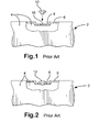
- FIG. 1 and 2 of the drawings An example of a prior art blow-moulded product made by the process described above is shown in Figures 1 and 2 of the drawings.
- the product 2 is a wall panel of a bulk container and the drawings show a portion of the wall panel, partially broken away.
- the panel includes two parallel rectangular side plates 4 that are interconnected by a peripheral wall 6.
- a shallow recess 8 is provided in one portion of the peripheral wall and a blowing hole 10 is located in that recess.
- a plug 12 is inserted and fixed in position. The recess allows the top of the plug 12 to lie flush with the edge of the panel, as shown in Figure 2.
- a method of blow-moulding including forming a parison of a thermoplastics material, closing a mould around the parison, injecting compressed gas into the parison through a blowing hole to form a moulded product that is shaped according to the shape of the mould, and deforming a seal forming portion of the moulded product with a heated sealing tool to seal the blowing hole.
- the invention allows the blowing hole to be sealed quickly and easily, without requiring an additional component. Production costs are thereby reduced. There is also a reduced risk of an incomplete seal and, because the seal is an integral part of the moulded product, it cannot work loose.
- the mould is shaped to provide the moulded product with a seal forming portion, which is preferably located adjacent the blowing hole.
- the seal forming portion may include a tubular collar that surrounds the blowing hole and extends outwards from the moulded product.
- the tubular collar may for example be moulded between an orifice in the mould and a gas injection needle that is inserted into the mould.
- the mould is preferably shaped to form a locking element that restricts movement between the tubular collar and the mould.
- the locking element may include a flange element that is provided on the tubular collar. This helps to prevent the tubular collar being pushed into the moulded product when the gas injection needle is inserted.
- the mould is shaped to provide the moulded product with a recess in the vicinity of the blowing hole and the seal forming portion is deformed to form a seal element that is located within the recess.
- This construction makes it possible to avoid having a seal element that protrudes outwards beyond the edges of the moulded product.
- a blow-moulded product including a hollow moulded body portion and a seal element that seals a blowing hole in the body portion, wherein the body portion and the seal element are made of a thermoplastics material and the seal element comprises a deformed seal forming portion of the body portion.
- the blow moulded product can be sealed quickly and easily, without requiring an additional component, with reduced production costs.
- the risk of an incomplete seal or a loose plug is significantly reduced.
- the seal forming portion is located within a recess provided in the moulded body portion.
- the blow-moulded product may for example comprise a wall panel of a container, or any other suitable product.
- FIG. 3 to 9 of the drawings illustrates a method of moulding a blow-moulded product 14 such as a simple rectangular wall panel, which may for example form part of a bulk container or crate.
- the wall panel which is shown in Figures 8 and 9, includes two parallel rectangular side plates 16 that are interconnected by a peripheral wall 18. It will be appreciated that many other products may also be made by substantially similar processes and that the present application is intended to cover such products and the processes for making them.
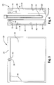
- the blow-moulding tool 20 shown in Figures 3 and 4 includes two symmetrically identical mould halves 22, each of which includes a mating surface 24 that in use mates against a corresponding surface on the other mould half, and a substantially rectangular mould cavity 26 that comprises a side face 28 for moulding a side plate 16 of the blow-moulded product and a surrounding peripheral face 30 for forming the peripheral wall 18 of the product.
- the peripheral face 30 includes a portion 32 that protrudes inwards, to form a recess 34 in the peripheral wall of the moulded product.
- a channel 36 is provided in the mating surface 24 of each mould half 22, at the location of the protruding portion. When the mould halves 22 are brought together, these channels 36 form an orifice 38 that extends through the mould tool 20 from the exterior to the interior of the mould cavity 26. This allows an air injection needle 40 to be inserted through the mould tool 20 into the mould cavity, for blowing compressed air into the parison, to inflate the moulded product 14 within the mould.
- blow-moulding tool 20 as described above are all conventional. Where the tool differs from prior art blow-moulding tools is in the shape of the orifice 38.
- this orifice generally consists simply of a cylindrical bore having a diameter slightly greater than that of the air injection needle 40, so as to allow the needle to be inserted.
- the orifice 38 includes an outer portion 3 8a comprising a cylindrical bore with a diameter slightly greater than that of the needle 40 (for example approximately 5mm), an inner portion 38b of slightly larger diameter (for example approximately 8mm) and an intermediate portion 38c of even larger diameter (for example approximately 10mm). It will be appreciated that the dimensions quoted above are only illustrative and are not intended to be limiting in any way.
- the inner and intermediate portions 38b, 38c of the orifice are therefore significantly larger than the needle 40, thus forming an annular gap between the needle 40 and the sides of the orifice 38.
- melted thermoplastics material is moulded in this gap to form a tubular collar, which is subsequently deformed to seal the blowing hole.
- a tube of heated thermoplastics material is extruded through an extrusion nozzle 42 into a gap between the two halves 22 of the mould, which at this stage is open.
- the extruded material forms a parison 44 comprising a hollow tube that is closed at its lower end.
- the mould 20 is then closed as shown in Figure 5.
- the upper part of the parison 44 is nipped between the two halves of the mould forming a plug of material within the orifice 38 in the upper part of the mould.
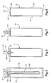
- the air injection needle 40 is then inserted through the orifice 38 into the parison 44 and compressed air is injected to inflate the parison, so forming a moulded product 14 matching the internal shape of the mould, as shown in Figure 6 (the mould tool has been omitted in this drawing for the sake of clarity).
- the needle 40 is withdrawn, leaving a blowing hole 45.
- the mould 20 is then opened and the moulded product 14 is removed.
- the moulded product 14 includes a tubular collar 46 that extends from the upper edge of the moulded product, this collar having been shaped within the gap between the wall of the orifice 38 and the air injection needle 40.
- the lower part of the collar 46 is substantially cylindrical, having been formed by the inner portion 38b of the orifice, and at its upper end the collar has an outwardly extending flange 48 formed by the intermediate portion 38c of the orifice.
- the collar 46 and the flange 48 provide a seal forming portion 49 of the moulded product, which may be deformed to seal the blowing hole 45.
- a heated sealing tool 50 is applied to the seal forming portion 49.
- the sealing tool 50 re-heats and melts the thermoplastics material of the seal forming portion 49 and squashes it downwards, thereby sealing the blowing hole 45.
- the remelted material thus forms a dome-like seal element 52 that is accommodated within the recess 34 in the edge of the moulded product 14, the upper part of the seal element 52 lying flush with or slightly below the edge of the product, as shown in Figures 8 and 9.
- the process described above thus provides a very simple method for sealing the blowing hole 45.
- the seal element 52 is formed as an integral part of the blow-moulded product 14, thereby obviating the need for a separate plug. Sealing the blowing hole 52 is a very simple process involving the application of a heated sealing tool 50. This process can be carried out manually or it can be automated, if desired.
- the shape of the seal forming portion 49 is important for successful sealing of the product.
- the seal forming portion 49 preferably comprises a tubular collar 46 having a flange 48 at its outer end.
- the flange 48 supports the collar 46 within the orifice 38 in the mould 20 and prevents it from being deformed as the needle 40 is inserted.
Landscapes
- Engineering & Computer Science (AREA)
- Mechanical Engineering (AREA)
- Manufacturing & Machinery (AREA)
- Blow-Moulding Or Thermoforming Of Plastics Or The Like (AREA)
Applications Claiming Priority (2)
| Application Number | Priority Date | Filing Date | Title |
|---|---|---|---|
| GB0327345 | 2003-11-25 | ||
| GB0327345A GB2408479B (en) | 2003-11-25 | 2003-11-25 | Method of blow-moulding and blow-moulded product |
Publications (1)
| Publication Number | Publication Date |
|---|---|
| EP1535724A1 true EP1535724A1 (fr) | 2005-06-01 |
Family
ID=29797741
Family Applications (1)
| Application Number | Title | Priority Date | Filing Date |
|---|---|---|---|
| EP04024285A Withdrawn EP1535724A1 (fr) | 2003-11-25 | 2004-10-12 | Procédé de moulage par soufflage |
Country Status (3)
| Country | Link |
|---|---|
| US (2) | US20050112306A1 (fr) |
| EP (1) | EP1535724A1 (fr) |
| GB (1) | GB2408479B (fr) |
Families Citing this family (1)
| Publication number | Priority date | Publication date | Assignee | Title |
|---|---|---|---|---|
| US7060159B2 (en) | 2003-04-04 | 2006-06-13 | Weyerhaeuser Company | Insulating paperboard |
Citations (7)
| Publication number | Priority date | Publication date | Assignee | Title |
|---|---|---|---|---|
| US4266927A (en) * | 1979-02-21 | 1981-05-12 | Baxter Travenol Laboratories, Inc. | Apparatus for molding a plastic article |
| JPS60228236A (ja) * | 1984-04-27 | 1985-11-13 | キヨ−ラク株式会社 | 中空容器 |
| JPS6237123A (ja) * | 1985-08-10 | 1987-02-18 | Showa Denko Kk | 合成樹脂製燃料タンクの製造方法 |
| JPH02261935A (ja) * | 1989-03-31 | 1990-10-24 | Inaba Rubber Kk | 緩衝体の製造方法 |
| JPH06286741A (ja) * | 1993-03-29 | 1994-10-11 | Kyoraku Co Ltd | 密閉中空容器およびその製造方法 |
| JPH08187769A (ja) * | 1995-01-06 | 1996-07-23 | Sekisui Chem Co Ltd | ブロー成形用金型及び中空成形体の製造方法 |
| JPH0958645A (ja) * | 1995-08-11 | 1997-03-04 | Kureha Plast Kk | ブローボトル |
Family Cites Families (4)
| Publication number | Priority date | Publication date | Assignee | Title |
|---|---|---|---|---|
| US3464085A (en) * | 1966-09-26 | 1969-09-02 | Dow Chemical Co | Packaging apparatus |
| US4842153A (en) * | 1988-04-04 | 1989-06-27 | Hulon Walter C | Biological product shipping tube |
| US5453001A (en) * | 1994-07-12 | 1995-09-26 | Huang; Kuo-Wen | Molding tool with blowing device |
| JP3892561B2 (ja) * | 1997-12-25 | 2007-03-14 | キョーラク株式会社 | 密封中空容器の製造方法 |
-
2003
- 2003-11-25 GB GB0327345A patent/GB2408479B/en not_active Expired - Fee Related
-
2004
- 2004-10-12 EP EP04024285A patent/EP1535724A1/fr not_active Withdrawn
- 2004-10-19 US US10/968,817 patent/US20050112306A1/en not_active Abandoned
-
2007
- 2007-08-31 US US11/849,161 patent/US20070292645A1/en not_active Abandoned
Patent Citations (7)
| Publication number | Priority date | Publication date | Assignee | Title |
|---|---|---|---|---|
| US4266927A (en) * | 1979-02-21 | 1981-05-12 | Baxter Travenol Laboratories, Inc. | Apparatus for molding a plastic article |
| JPS60228236A (ja) * | 1984-04-27 | 1985-11-13 | キヨ−ラク株式会社 | 中空容器 |
| JPS6237123A (ja) * | 1985-08-10 | 1987-02-18 | Showa Denko Kk | 合成樹脂製燃料タンクの製造方法 |
| JPH02261935A (ja) * | 1989-03-31 | 1990-10-24 | Inaba Rubber Kk | 緩衝体の製造方法 |
| JPH06286741A (ja) * | 1993-03-29 | 1994-10-11 | Kyoraku Co Ltd | 密閉中空容器およびその製造方法 |
| JPH08187769A (ja) * | 1995-01-06 | 1996-07-23 | Sekisui Chem Co Ltd | ブロー成形用金型及び中空成形体の製造方法 |
| JPH0958645A (ja) * | 1995-08-11 | 1997-03-04 | Kureha Plast Kk | ブローボトル |
Non-Patent Citations (6)
| Title |
|---|
| DATABASE WPI Week 198601, Derwent World Patents Index; AN 1986-002997, XP002319400 * |
| PATENT ABSTRACTS OF JAPAN vol. 011, no. 221 (M - 608) 17 July 1987 (1987-07-17) * |
| PATENT ABSTRACTS OF JAPAN vol. 015, no. 010 (M - 1068) 10 January 1991 (1991-01-10) * |
| PATENT ABSTRACTS OF JAPAN vol. 1995, no. 01 28 February 1995 (1995-02-28) * |
| PATENT ABSTRACTS OF JAPAN vol. 1996, no. 11 29 November 1996 (1996-11-29) * |
| PATENT ABSTRACTS OF JAPAN vol. 1997, no. 07 31 July 1997 (1997-07-31) * |
Also Published As
| Publication number | Publication date |
|---|---|
| GB0327345D0 (en) | 2003-12-31 |
| GB2408479B (en) | 2008-03-26 |
| US20070292645A1 (en) | 2007-12-20 |
| US20050112306A1 (en) | 2005-05-26 |
| GB2408479A (en) | 2005-06-01 |
Similar Documents
| Publication | Publication Date | Title |
|---|---|---|
| AU2008346549B2 (en) | Method and device for producing containers made of thermoplastic and containers so produced | |
| RU2560418C2 (ru) | Способ изготовления пластмассового изделия, а также раздувная форма для осуществления этого способа | |
| US5989482A (en) | Method and apparatus for manufacturing multi-layer bottle | |
| CN105538660A (zh) | 用于制造压力容器的方法和工具以及压力容器 | |
| US6645421B1 (en) | Method for making a plastic container | |
| US20190300277A1 (en) | Waste water container | |
| EP0713827B1 (fr) | Procédé de fabrication de récipients distributeurs de liquide | |
| EP2740581B1 (fr) | Procédé pour la fabrication de conduits d'air en plastique et moule utilisé | |
| US7141202B2 (en) | Method and apparatus for blow molding a bottle with a punched hole in a molded neck recess | |
| EP1535724A1 (fr) | Procédé de moulage par soufflage | |
| US20170021551A1 (en) | Tooling, system, and process for injection stretch blow molded container with integral handle | |
| CN108136655A (zh) | 多室容器的制造装置及其制造方法 | |
| JP3285952B2 (ja) | ブロー成形におけるインサート方法 | |
| CN115503213B (zh) | 用于制造容器的方法 | |
| CN113134962B (zh) | 用于利用至少一个连接元件吹塑塑料箱的方法和工具 | |
| KR100231163B1 (ko) | 내용물이 충진된 용기의 제조장치 | |
| US12564542B2 (en) | Medical fluid container | |
| US6551544B1 (en) | Shuttle blow molding method and apparatus | |
| US20230191686A1 (en) | Method and tool for producing a plastic container, particularly a fuel container, by internal pressure forming | |
| KR100237493B1 (ko) | 용기 성형 방법 | |
| US20060177537A1 (en) | Apparatus for blow molding | |
| JP2601992B2 (ja) | ブロー成形装置 | |
| US20040107551A1 (en) | Indented female blow-molded connector | |
| KR100231164B1 (ko) | 내용물이 충진된 용기의 제조방법 | |
| US20230038767A1 (en) | Blow mold, stretch blow molder and method for forming a container |
Legal Events
| Date | Code | Title | Description |
|---|---|---|---|
| PUAI | Public reference made under article 153(3) epc to a published international application that has entered the european phase |
Free format text: ORIGINAL CODE: 0009012 |
|
| AK | Designated contracting states |
Kind code of ref document: A1 Designated state(s): AT BE BG CH CY CZ DE DK EE ES FI FR GB GR HU IE IT LI LU MC NL PL PT RO SE SI SK TR |
|
| AX | Request for extension of the european patent |
Extension state: AL HR LT LV MK |
|
| RAP1 | Party data changed (applicant data changed or rights of an application transferred) |
Owner name: LINPAC MATERIALS HANDLING LIMITED |
|
| 17P | Request for examination filed |
Effective date: 20051128 |
|
| AKX | Designation fees paid |
Designated state(s): AT BE BG CH CY CZ DE DK EE ES FI FR GB GR HU IE IT LI LU MC NL PL PT RO SE SI SK TR |
|
| RIN1 | Information on inventor provided before grant (corrected) |
Inventor name: MELIA, MICHAEL J. |
|
| STAA | Information on the status of an ep patent application or granted ep patent |
Free format text: STATUS: THE APPLICATION IS DEEMED TO BE WITHDRAWN |
|
| 18D | Application deemed to be withdrawn |
Effective date: 20060509 |