EP1535819A1 - Einheit zum sicheren Messen oder Erkennen eines elektrischen Stroms einer sicherungstechnischen Einrichtung - Google Patents
Einheit zum sicheren Messen oder Erkennen eines elektrischen Stroms einer sicherungstechnischen Einrichtung Download PDFInfo
- Publication number
- EP1535819A1 EP1535819A1 EP04078116A EP04078116A EP1535819A1 EP 1535819 A1 EP1535819 A1 EP 1535819A1 EP 04078116 A EP04078116 A EP 04078116A EP 04078116 A EP04078116 A EP 04078116A EP 1535819 A1 EP1535819 A1 EP 1535819A1
- Authority
- EP
- European Patent Office
- Prior art keywords
- current
- unit
- sensor
- test
- magnetic field
- Prior art date
- Legal status (The legal status is an assumption and is not a legal conclusion. Google has not performed a legal analysis and makes no representation as to the accuracy of the status listed.)
- Granted
Links
- 238000005259 measurement Methods 0.000 title description 5
- 238000001514 detection method Methods 0.000 title 1
- 238000012360 testing method Methods 0.000 claims abstract description 17
- 238000000034 method Methods 0.000 claims description 3
- 230000001419 dependent effect Effects 0.000 claims description 2
- 238000010586 diagram Methods 0.000 description 6
- 238000013461 design Methods 0.000 description 3
- 238000002955 isolation Methods 0.000 description 3
- 230000003287 optical effect Effects 0.000 description 3
- 238000000926 separation method Methods 0.000 description 2
- 238000006243 chemical reaction Methods 0.000 description 1
- 230000008878 coupling Effects 0.000 description 1
- 238000010168 coupling process Methods 0.000 description 1
- 238000005859 coupling reaction Methods 0.000 description 1
- 230000005611 electricity Effects 0.000 description 1
- 238000005516 engineering process Methods 0.000 description 1
- 230000035945 sensitivity Effects 0.000 description 1
- 238000012546 transfer Methods 0.000 description 1
Images


Classifications
-
- B—PERFORMING OPERATIONS; TRANSPORTING
- B61—RAILWAYS
- B61L—GUIDING RAILWAY TRAFFIC; ENSURING THE SAFETY OF RAILWAY TRAFFIC
- B61L5/00—Local operating mechanisms for points or track-mounted scotch-blocks; Visible or audible signals; Local operating mechanisms for visible or audible signals
- B61L5/12—Visible signals
- B61L5/18—Light signals; Mechanisms associated therewith, e.g. blinders
- B61L5/1809—Daylight signals
- B61L5/1881—Wiring diagrams for power supply, control or testing
-
- G—PHYSICS
- G01—MEASURING; TESTING
- G01R—MEASURING ELECTRIC VARIABLES; MEASURING MAGNETIC VARIABLES
- G01R15/00—Details of measuring arrangements of the types provided for in groups G01R17/00 - G01R29/00, G01R33/00 - G01R33/26 or G01R35/00
- G01R15/14—Adaptations providing voltage or current isolation, e.g. for high-voltage or high-current networks
- G01R15/20—Adaptations providing voltage or current isolation, e.g. for high-voltage or high-current networks using galvano-magnetic devices, e.g. Hall-effect devices, i.e. measuring a magnetic field via the interaction between a current and a magnetic field, e.g. magneto resistive or Hall effect devices
- G01R15/202—Adaptations providing voltage or current isolation, e.g. for high-voltage or high-current networks using galvano-magnetic devices, e.g. Hall-effect devices, i.e. measuring a magnetic field via the interaction between a current and a magnetic field, e.g. magneto resistive or Hall effect devices using Hall-effect devices
-
- G—PHYSICS
- G01—MEASURING; TESTING
- G01R—MEASURING ELECTRIC VARIABLES; MEASURING MAGNETIC VARIABLES
- G01R19/00—Arrangements for measuring currents or voltages or for indicating presence or sign thereof
- G01R19/145—Indicating the presence of current or voltage
- G01R19/15—Indicating the presence of current
-
- G—PHYSICS
- G01—MEASURING; TESTING
- G01R—MEASURING ELECTRIC VARIABLES; MEASURING MAGNETIC VARIABLES
- G01R35/00—Testing or calibrating of apparatus covered by the other groups of this subclass
Definitions
- the invention relates to a unit for safe measuring or Detecting an electric current of a fuse Device according to the preamble of claim 1.
- a current transformer be used, which was traversed by a current to be measured Has primary coil.
- the current transformer carries galvanic separated from the primary coil, a secondary coil, the like a sensor depending on the magnetic field of the primary coil emits an AC signal.
- a power transformer always has a big volume.
- a relay in a safety design to achieve the required galvanic isolation too use.
- the relay will be in series with the one to be measured Power is switched on and opens its mechanical contacts when the current exceeds a predetermined value.
- These too Design has a relatively large volume at a high cost on, with the addition that the mechanical contacts of the relay wear out over time.
- the relay is used in the described operation as a current window for detecting an electric current with a minimum current value. It is also possible to design the relay so that it is at a maximum current value turns off again, so it detects if the Electricity is located in a given power window.
- the object of the invention is a small-volume unit for safely measuring or detecting an electric current which is additionally inexpensive.
- the unit for safe measuring or detecting an electric current two independent Components includes that in the area of the sensor a test coil is arranged, controlled by a the two components at least one in current value and current direction given current pulse is sent, the test magnetic field generated by the current pulse changes the sensor signal, and that the functioning of the unit from the other Component is checked against the change. In this way the measurement can be done easily.
- the unit works with both types of current, alternating current as well DC. It has a low volume and is at low cost. The unit is wear-free, since there are no mechanical contacts. With low Effort is a high potential separation possible.
- a constructive simple universal unit has one secure computer with two independent channels as independent Components on.
- the senor is through the two successively arranged cylindrical coils therethrough plugged.
- the unit is for testing a potential-free contact query in the application "Detecting an electric current" a fuse unit used when the primary coil has a current limit.
- the usability of the unit can be increased if the Unit is designed as a module, that the module becomes a group of combinable ones Function modules belongs, their functions each different Process connections for safe operation of securing facilities are common, and that at least one more functional module of the safe Calculator is.
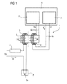
- Fig. 1 shows a unit 1 for safe measurement or recognition of an electrical current leading to a process connection, not shown for the safe operation of a safety-related Institution belong, so for example for the Control of signal lamps, turnouts, axle counters, Free field devices, speed measuring devices and driving locks as well as for secure contact queries.
- the unit 1 is connected to a consumer 2 in the form of a signal lamp 2a connected, through which a current Ip in the shown Arrow direction by the consumer 2 flows.
- a current Ip in the shown Arrow direction by the consumer 2 flows.
- the Consumer 2 is connected in series with a primary coil 3.
- the consumer 2 the primary coil 3 and a switch 4 make up the primary circuit.
- On the primary circuit is a Voltage Up on or drops the voltage Up.
- the primary coil 3 is in Fig. 1 as a cylindrical coil with a central Through-hole through which a sensor 5 passes, the magnetic field strength Hp of the primary coil 3 in a voltage signal (voltage Us) converts.
- Located in the sensor 5 a not-shown Hall sensor, which is the conversion performs.
- both Coils 3, 6 are arranged one behind the other.
- the sensor 5 runs as shown in FIG. 1 also by central opening this Coil 6 through. The distance between the two coils 5, 6 is so chosen that ensures sufficient electrical isolation is.
- the sensor 5 and the test coil 6 are each with each other independent components 7, 8 of a secure computer 9, where it is the two components 7, 8 by two independent channels of the computer 9 acts.
- connection 6a of the computer 9 Via the connection 6a of the computer 9, these current pulses send through the test coil 6, with a predetermined Current value and a given current direction.
- This control is performed by the component 7.
- the current pulse generated by means of the test coil 6, a test magnetic field Ht, both Coils 5, 6 are arranged so close together that this Test magnetic field corresponding to the magnetic field of the primary coil 3 the current pulse (current value, current direction) changes. Thereby there is a change in the magnetic field dependent Voltage signal (voltage Us) of the sensor.
- the change will detected by the other component 8 of the computer 9 (connection 6b) and in this way the functioning of the unit checked.
- the corresponding timing diagrams are shown in FIG.
- the upper diagram shows a digital current profile Ip as a function of time t.
- the middle diagram shows a Sequence of digital test pulses, i. Current pulses It with the reference numeral 10 as a function of time t.
- the lower diagram sets the voltage Us (sensor signal) at the input of the Component 8 and the output of the sensor 5 as a function of Time t. This diagram shows that when flawless Function of the unit 1, the current pulses 10 to a corresponding increase or decrease in the voltage Us leads.
- components 8 are merely checked whether there is a change in the voltage Us in the corresponding Direction comes, from which then the correct function the unit 1 is derived.
- Fig. 3 illustrates the unit in connection with a test a potential-free contact query of a fuse-technical Device, it is only on the recognition of an electric current Ip arrives.
- the consumer 2 here is a contact 11 to be monitored, which is shown in Fig. 3 in the open state.
- the functioning the unit 1 is analogous to that shown in FIG. 1. However must be a current limit 12 in order to protect the unit be connected to the primary circuit.
Landscapes
- Engineering & Computer Science (AREA)
- Mechanical Engineering (AREA)
- Measuring Instrument Details And Bridges, And Automatic Balancing Devices (AREA)
- Fuses (AREA)
- Measurement Of Current Or Voltage (AREA)
- Electrotherapy Devices (AREA)
- Emergency Protection Circuit Devices (AREA)
Abstract
Description
- Fig. 1
- eine Einheit zum sicheren Messen oder Erkennen eines elektrischen Stroms,
- Fig. 2
- Zeitdiagramme der Einheit gemäß Fig. 1 und
- Fig. 3
- eine sichere Kontaktabfrageeinrichtung unter Verwendung der Einheit gemäß Fig. 1.
Claims (5)
- Einheit (1) zum sicheren Messen oder Erkennen eines elektrischen Stroms einer sicherungstechnischen Einrichtung (2a, 11), insbesondere einer Signallampe (2a), eines Weichenantriebs, eines Achszählers, einer Freimeldeeinrichtung und dergleichen sowie eine sichere Kontaktabfrageeinrichtung,
mit einer vom Strom durchflossenen Primärspule (3) zur Erzeugung eines Magnetfeldes (Hp), das von einem galvanisch von der Primärspule (2a) getrennten Sensor (5) in ein magnetfeldabhängiges Sensorsignal (Us) umgewandelt wird, und
mit einer Prüfspule (6), durch die gesteuert von einem Rechner (9) ein in Stromwert und Stromrichtung vorgegebener Strom geschickt wird, wobei das vom Strom erzeugte Prüfmagnetfeld (Ht) das Sensorsignal (Us) ändert und das Funktionieren der Einheit (1) anhand der Änderung des Sensorsignals (Us) geprüft wird,
dadurch gekennzeichnet, dass der Rechner (9) sicherungstechnisch sicher zwei voneinander unabhängige Kanäle (7, 8) aufweist,
dass der Strom durch die Prüfspule (6) als Stromimpuls (10) von einem der beiden Kanäle (7 oder 8)geschickt wird und
dass das Funktionieren der Einheit (1) vom anderen Kanal (8 bzw. 7) anhand der Änderung geprüft wird. - Einheit (1) nach Anspruch 1,
dadurch gekennzeichnet, dass der Sensor (5) durch die beiden hintereinander angeordneten zylindrischen Spulen (3, 6) hindurch gesteckt ist. - Einheit (1) nach Anspruch 1 oder 2,
dadurch gekennzeichnet, dass der Sensor (5) einen Hall-Sensor aufweist. - Einheit (1) nach einem der Ansprüche 1 - 3,
dadurch gekennzeichnet, dass die Einheit (1) zur Prüfung einer potentialfreien Kontaktabfrage in der Anwendung "Erkennen eines elektrischen Stroms einer sicherungstechnischen Einrichtung" verwendbar ist, wobei der Primärspule (3) eine Strombegrenzung (12) vorzuschalten ist. - Einheit (1) nach einem der Ansprüche 1 - 4,
dadurch gekennzeichnet, dass die Einheit (1) als Modul ausgebildet ist,
dass das Modul zu einer Gruppe von miteinander kombinierbaren Funktions-Modulen gehört, deren Funktionalitäten jeweils unterschiedlichen Prozessanschaltungen für das sichere Betreiben von sicherungstechnischen Einrichtungen (2a, 11) gemeinsam sind, und dass zumindest ein weiteres Funktions-Modul der sichere Rechner (9) ist.
Applications Claiming Priority (2)
| Application Number | Priority Date | Filing Date | Title |
|---|---|---|---|
| DE10355861 | 2003-11-25 | ||
| DE10355861A DE10355861A1 (de) | 2003-11-25 | 2003-11-25 | Einheit zum sicheren Messen oder Erkennen eines elektrischen Stroms einer sicherungstechnischen Einrichtung |
Publications (2)
| Publication Number | Publication Date |
|---|---|
| EP1535819A1 true EP1535819A1 (de) | 2005-06-01 |
| EP1535819B1 EP1535819B1 (de) | 2006-06-07 |
Family
ID=34442352
Family Applications (1)
| Application Number | Title | Priority Date | Filing Date |
|---|---|---|---|
| EP04078116A Expired - Lifetime EP1535819B1 (de) | 2003-11-25 | 2004-11-11 | Einheit zum sicheren Messen oder Erkennen eines elektrischen Stroms einer sicherungstechnischen Einrichtung |
Country Status (6)
| Country | Link |
|---|---|
| EP (1) | EP1535819B1 (de) |
| AT (1) | ATE328774T1 (de) |
| DE (2) | DE10355861A1 (de) |
| DK (1) | DK1535819T3 (de) |
| ES (1) | ES2266984T3 (de) |
| PT (1) | PT1535819E (de) |
Cited By (1)
| Publication number | Priority date | Publication date | Assignee | Title |
|---|---|---|---|---|
| CN105527486A (zh) * | 2016-01-05 | 2016-04-27 | 深圳博科智能科技有限公司 | 智能检电夹 |
Families Citing this family (1)
| Publication number | Priority date | Publication date | Assignee | Title |
|---|---|---|---|---|
| DE102004057449B3 (de) * | 2004-11-24 | 2006-07-20 | Siemens Ag | Schaltung zur Ansteuerung und Überwachung einer Mehrzahl von Signallampen |
Citations (3)
| Publication number | Priority date | Publication date | Assignee | Title |
|---|---|---|---|---|
| US3710364A (en) * | 1970-01-15 | 1973-01-09 | Daimler Benz Ag | Monitoring installation of the lighting system of motor vehicles |
| DE3140559A1 (de) * | 1981-10-13 | 1983-04-28 | Standard Elektrik Lorenz Ag, 7000 Stuttgart | Schaltungsanordnung zum signaltechnisch sicheren betrieb von signallampen |
| US5041817A (en) * | 1988-04-15 | 1991-08-20 | Daimler-Benz Ag | Arrangement for the inductive querying of and supplying of power to an isolated circuit having an electrical consuming device |
Family Cites Families (7)
| Publication number | Priority date | Publication date | Assignee | Title |
|---|---|---|---|---|
| IT1108241B (it) * | 1978-05-29 | 1985-12-02 | Finike Italiana Marposs | Apaprecchiatura elettronica modulare per controlli multipli simultanei |
| DE3905060A1 (de) * | 1989-02-18 | 1990-08-23 | Diehl Gmbh & Co | Einrichtung zum beruehrungslosen messen eines gleichstroms |
| DE4230939C2 (de) * | 1992-09-16 | 1995-04-06 | Heidelberger Druckmasch Ag | Schaltungsanordnung zum Ändern oder Prüfen elektrischer Eigenschaften eines Stromwandlers mit Magnetfeldkompensation |
| DE19537354B4 (de) * | 1995-10-06 | 2004-03-18 | Siemens Ag | Verfahren und Vorrichtung zur Bestimmung eines Stromwertes eines digital geregelten Leistungsteils |
| DE10107791A1 (de) * | 2001-02-13 | 2002-08-14 | Daimler Chrysler Ag | Verfahren und Anordnung zur Messung eines elektrischen Stroms in einem schaltenden Leistungshalbleiterbauelement |
| WO2003014452A1 (de) * | 2001-08-07 | 2003-02-20 | Frank Eilers | Meldevorrichtung für einen gerätebetriebszustand |
| US6570373B1 (en) * | 2002-03-07 | 2003-05-27 | Visteon Global Technologies, Inc. | Current sensor programmable through connector |
-
2003
- 2003-11-25 DE DE10355861A patent/DE10355861A1/de not_active Withdrawn
-
2004
- 2004-11-11 PT PT04078116T patent/PT1535819E/pt unknown
- 2004-11-11 DK DK04078116T patent/DK1535819T3/da active
- 2004-11-11 ES ES04078116T patent/ES2266984T3/es not_active Expired - Lifetime
- 2004-11-11 AT AT04078116T patent/ATE328774T1/de active
- 2004-11-11 EP EP04078116A patent/EP1535819B1/de not_active Expired - Lifetime
- 2004-11-11 DE DE502004000702T patent/DE502004000702D1/de not_active Expired - Lifetime
Patent Citations (3)
| Publication number | Priority date | Publication date | Assignee | Title |
|---|---|---|---|---|
| US3710364A (en) * | 1970-01-15 | 1973-01-09 | Daimler Benz Ag | Monitoring installation of the lighting system of motor vehicles |
| DE3140559A1 (de) * | 1981-10-13 | 1983-04-28 | Standard Elektrik Lorenz Ag, 7000 Stuttgart | Schaltungsanordnung zum signaltechnisch sicheren betrieb von signallampen |
| US5041817A (en) * | 1988-04-15 | 1991-08-20 | Daimler-Benz Ag | Arrangement for the inductive querying of and supplying of power to an isolated circuit having an electrical consuming device |
Cited By (1)
| Publication number | Priority date | Publication date | Assignee | Title |
|---|---|---|---|---|
| CN105527486A (zh) * | 2016-01-05 | 2016-04-27 | 深圳博科智能科技有限公司 | 智能检电夹 |
Also Published As
| Publication number | Publication date |
|---|---|
| DK1535819T3 (da) | 2006-10-02 |
| EP1535819B1 (de) | 2006-06-07 |
| ATE328774T1 (de) | 2006-06-15 |
| DE502004000702D1 (de) | 2006-07-20 |
| PT1535819E (pt) | 2006-09-29 |
| ES2266984T3 (es) | 2007-03-01 |
| DE10355861A1 (de) | 2005-07-07 |
Similar Documents
| Publication | Publication Date | Title |
|---|---|---|
| EP1058093B1 (de) | Verfahren und Schaltungsanordnung zur Spannungsversorgung und Funktionsüberwachung zumindest eines Messwertumformers | |
| DE102007046483A1 (de) | Schaltungsanordnung zur Überwachung einer elektrischen Isolation | |
| EP2623996B1 (de) | Strommessschaltung und Verfahren zur Überwachung einer Funktionsfähigkeit einer Strommessschaltung | |
| EP1665483B1 (de) | Einrichtung zur überwachung des leckstroms eines überspannungsableiters | |
| DE102014103321A1 (de) | Isolationsüberwachung für reihenkompensierte Wicklungen eines kontaktlosen Energieübertragungssystems | |
| DE4410735A1 (de) | Einrichtung mit einem Feuerungsautomaten | |
| EP1535819B1 (de) | Einheit zum sicheren Messen oder Erkennen eines elektrischen Stroms einer sicherungstechnischen Einrichtung | |
| EP1340988A2 (de) | Verfahren und Vorrichtung zur Messung der Impedanz eines elektrischen Energieversorgungsnetzes | |
| DE3505765A1 (de) | Induktiver naeherungsschalter mit pruefeinrichtung | |
| DE102016212211A1 (de) | Kurzschlusserkennung | |
| DE19758101C2 (de) | Elektronische Einrichtung zur Überwachung eines Schaltgerätes in einem elektrischen System | |
| EP1034553A1 (de) | Schaltung zur überwachung eines wechselstromschalters | |
| DE19906932B4 (de) | Binäreingabegerät | |
| DE2842965A1 (de) | Schaltung zur unterscheidung von hohen gleich- oder wechselspannungen | |
| DE3338490C2 (de) | ||
| DE3043255C2 (de) | ||
| DE102020110000A1 (de) | Elektrische Schaltungsanordnung und Verfahren zur galvanisch getrennten, allstromsensitiven Differenzstrom-Messung mit hoher Auflösung | |
| EP2117094B1 (de) | Überwachungsschaltung und Verfahren zum Prüfen der Schaltung | |
| DE10314261B4 (de) | Brückenschaltung zur Abfrage eines Schalters | |
| EP2876509B1 (de) | Sicherheitssteuerung | |
| EP1363378B9 (de) | Verfahren und Vorrichtung zur Kurzschlusserkennung und zum Überspannungsschutz in Zweispannungsbordnetzen | |
| DE2848791C3 (de) | Anordnung zur Überwachung hochgespannter Ströme | |
| EP1003967B1 (de) | Mess- und diagnoseeinrichtung für ein zündsystem einer brennkraftmaschine | |
| DE2403769A1 (de) | Testbarer, stoersignalunempfindlicher festkoerperschalter mit phasenausgang | |
| EP1610134B1 (de) | Gesteuerter Gleichrichter für LED-Signalgeber |
Legal Events
| Date | Code | Title | Description |
|---|---|---|---|
| PUAI | Public reference made under article 153(3) epc to a published international application that has entered the european phase |
Free format text: ORIGINAL CODE: 0009012 |
|
| AK | Designated contracting states |
Kind code of ref document: A1 Designated state(s): AT BE BG CH CY CZ DE DK EE ES FI FR GB GR HU IE IS IT LI LU MC NL PL PT RO SE SI SK TR |
|
| AX | Request for extension of the european patent |
Extension state: AL HR LT LV MK YU |
|
| GRAP | Despatch of communication of intention to grant a patent |
Free format text: ORIGINAL CODE: EPIDOSNIGR1 |
|
| 17P | Request for examination filed |
Effective date: 20051107 |
|
| AKX | Designation fees paid |
Designated state(s): AT BE BG CH CY CZ DE DK EE ES FI FR GB GR HU IE IS IT LI LU MC NL PL PT RO SE SI SK TR |
|
| GRAS | Grant fee paid |
Free format text: ORIGINAL CODE: EPIDOSNIGR3 |
|
| GRAA | (expected) grant |
Free format text: ORIGINAL CODE: 0009210 |
|
| AK | Designated contracting states |
Kind code of ref document: B1 Designated state(s): AT BE BG CH CY CZ DE DK EE ES FI FR GB GR HU IE IS IT LI LU MC NL PL PT RO SE SI SK TR |
|
| PG25 | Lapsed in a contracting state [announced via postgrant information from national office to epo] |
Ref country code: IT Free format text: LAPSE BECAUSE OF FAILURE TO SUBMIT A TRANSLATION OF THE DESCRIPTION OR TO PAY THE FEE WITHIN THE PRESCRIBED TIME-LIMIT;WARNING: LAPSES OF ITALIAN PATENTS WITH EFFECTIVE DATE BEFORE 2007 MAY HAVE OCCURRED AT ANY TIME BEFORE 2007. THE CORRECT EFFECTIVE DATE MAY BE DIFFERENT FROM THE ONE RECORDED. Effective date: 20060607 Ref country code: CZ Free format text: LAPSE BECAUSE OF FAILURE TO SUBMIT A TRANSLATION OF THE DESCRIPTION OR TO PAY THE FEE WITHIN THE PRESCRIBED TIME-LIMIT Effective date: 20060607 Ref country code: IS Free format text: LAPSE BECAUSE OF FAILURE TO SUBMIT A TRANSLATION OF THE DESCRIPTION OR TO PAY THE FEE WITHIN THE PRESCRIBED TIME-LIMIT Effective date: 20060607 Ref country code: SK Free format text: LAPSE BECAUSE OF FAILURE TO SUBMIT A TRANSLATION OF THE DESCRIPTION OR TO PAY THE FEE WITHIN THE PRESCRIBED TIME-LIMIT Effective date: 20060607 Ref country code: IE Free format text: LAPSE BECAUSE OF FAILURE TO SUBMIT A TRANSLATION OF THE DESCRIPTION OR TO PAY THE FEE WITHIN THE PRESCRIBED TIME-LIMIT Effective date: 20060607 Ref country code: RO Free format text: LAPSE BECAUSE OF FAILURE TO SUBMIT A TRANSLATION OF THE DESCRIPTION OR TO PAY THE FEE WITHIN THE PRESCRIBED TIME-LIMIT Effective date: 20060607 Ref country code: PL Free format text: LAPSE BECAUSE OF FAILURE TO SUBMIT A TRANSLATION OF THE DESCRIPTION OR TO PAY THE FEE WITHIN THE PRESCRIBED TIME-LIMIT Effective date: 20060607 Ref country code: SI Free format text: LAPSE BECAUSE OF FAILURE TO SUBMIT A TRANSLATION OF THE DESCRIPTION OR TO PAY THE FEE WITHIN THE PRESCRIBED TIME-LIMIT Effective date: 20060607 |
|
| REG | Reference to a national code |
Ref country code: GB Ref legal event code: FG4D Free format text: NOT ENGLISH |
|
| REG | Reference to a national code |
Ref country code: CH Ref legal event code: EP |
|
| REG | Reference to a national code |
Ref country code: CH Ref legal event code: NV Representative=s name: SIEMENS SCHWEIZ AG |
|
| GBT | Gb: translation of ep patent filed (gb section 77(6)(a)/1977) |
Effective date: 20060613 |
|
| REG | Reference to a national code |
Ref country code: IE Ref legal event code: FG4D Free format text: LANGUAGE OF EP DOCUMENT: GERMAN |
|
| REF | Corresponds to: |
Ref document number: 502004000702 Country of ref document: DE Date of ref document: 20060720 Kind code of ref document: P |
|
| REG | Reference to a national code |
Ref country code: SE Ref legal event code: TRGR |
|
| REG | Reference to a national code |
Ref country code: PT Ref legal event code: SC4A Effective date: 20060728 |
|
| REG | Reference to a national code |
Ref country code: DK Ref legal event code: T3 |
|
| PG25 | Lapsed in a contracting state [announced via postgrant information from national office to epo] |
Ref country code: MC Free format text: LAPSE BECAUSE OF NON-PAYMENT OF DUE FEES Effective date: 20061130 |
|
| REG | Reference to a national code |
Ref country code: IE Ref legal event code: FD4D |
|
| REG | Reference to a national code |
Ref country code: ES Ref legal event code: FG2A Ref document number: 2266984 Country of ref document: ES Kind code of ref document: T3 |
|
| PLBE | No opposition filed within time limit |
Free format text: ORIGINAL CODE: 0009261 |
|
| STAA | Information on the status of an ep patent application or granted ep patent |
Free format text: STATUS: NO OPPOSITION FILED WITHIN TIME LIMIT |
|
| EN | Fr: translation not filed | ||
| 26N | No opposition filed |
Effective date: 20070308 |
|
| PG25 | Lapsed in a contracting state [announced via postgrant information from national office to epo] |
Ref country code: FR Free format text: LAPSE BECAUSE OF FAILURE TO SUBMIT A TRANSLATION OF THE DESCRIPTION OR TO PAY THE FEE WITHIN THE PRESCRIBED TIME-LIMIT Effective date: 20070309 Ref country code: GR Free format text: LAPSE BECAUSE OF FAILURE TO SUBMIT A TRANSLATION OF THE DESCRIPTION OR TO PAY THE FEE WITHIN THE PRESCRIBED TIME-LIMIT Effective date: 20060908 |
|
| PG25 | Lapsed in a contracting state [announced via postgrant information from national office to epo] |
Ref country code: EE Free format text: LAPSE BECAUSE OF FAILURE TO SUBMIT A TRANSLATION OF THE DESCRIPTION OR TO PAY THE FEE WITHIN THE PRESCRIBED TIME-LIMIT Effective date: 20060607 Ref country code: BG Free format text: LAPSE BECAUSE OF FAILURE TO SUBMIT A TRANSLATION OF THE DESCRIPTION OR TO PAY THE FEE WITHIN THE PRESCRIBED TIME-LIMIT Effective date: 20060907 |
|
| PG25 | Lapsed in a contracting state [announced via postgrant information from national office to epo] |
Ref country code: TR Free format text: LAPSE BECAUSE OF FAILURE TO SUBMIT A TRANSLATION OF THE DESCRIPTION OR TO PAY THE FEE WITHIN THE PRESCRIBED TIME-LIMIT Effective date: 20060607 Ref country code: HU Free format text: LAPSE BECAUSE OF FAILURE TO SUBMIT A TRANSLATION OF THE DESCRIPTION OR TO PAY THE FEE WITHIN THE PRESCRIBED TIME-LIMIT Effective date: 20061208 Ref country code: LU Free format text: LAPSE BECAUSE OF NON-PAYMENT OF DUE FEES Effective date: 20061111 |
|
| PG25 | Lapsed in a contracting state [announced via postgrant information from national office to epo] |
Ref country code: CY Free format text: LAPSE BECAUSE OF FAILURE TO SUBMIT A TRANSLATION OF THE DESCRIPTION OR TO PAY THE FEE WITHIN THE PRESCRIBED TIME-LIMIT Effective date: 20060607 Ref country code: FR Free format text: LAPSE BECAUSE OF FAILURE TO SUBMIT A TRANSLATION OF THE DESCRIPTION OR TO PAY THE FEE WITHIN THE PRESCRIBED TIME-LIMIT Effective date: 20060607 |
|
| PGFP | Annual fee paid to national office [announced via postgrant information from national office to epo] |
Ref country code: DK Payment date: 20081105 Year of fee payment: 5 Ref country code: NL Payment date: 20081111 Year of fee payment: 5 |
|
| PGFP | Annual fee paid to national office [announced via postgrant information from national office to epo] |
Ref country code: PT Payment date: 20081022 Year of fee payment: 5 |
|
| REG | Reference to a national code |
Ref country code: CH Ref legal event code: PCAR Free format text: SIEMENS SCHWEIZ AG;INTELLECTUAL PROPERTY FREILAGERSTRASSE 40;8047 ZUERICH (CH) |
|
| REG | Reference to a national code |
Ref country code: PT Ref legal event code: MM4A Free format text: LAPSE DUE TO NON-PAYMENT OF FEES Effective date: 20100511 |
|
| REG | Reference to a national code |
Ref country code: NL Ref legal event code: V1 Effective date: 20100601 |
|
| REG | Reference to a national code |
Ref country code: DK Ref legal event code: EBP |
|
| PG25 | Lapsed in a contracting state [announced via postgrant information from national office to epo] |
Ref country code: PT Free format text: LAPSE BECAUSE OF NON-PAYMENT OF DUE FEES Effective date: 20100511 |
|
| PG25 | Lapsed in a contracting state [announced via postgrant information from national office to epo] |
Ref country code: NL Free format text: LAPSE BECAUSE OF NON-PAYMENT OF DUE FEES Effective date: 20100601 |
|
| PG25 | Lapsed in a contracting state [announced via postgrant information from national office to epo] |
Ref country code: DK Free format text: LAPSE BECAUSE OF NON-PAYMENT OF DUE FEES Effective date: 20091130 |
|
| PGFP | Annual fee paid to national office [announced via postgrant information from national office to epo] |
Ref country code: SE Payment date: 20141106 Year of fee payment: 11 Ref country code: FI Payment date: 20141112 Year of fee payment: 11 |
|
| PG25 | Lapsed in a contracting state [announced via postgrant information from national office to epo] |
Ref country code: SE Free format text: LAPSE BECAUSE OF NON-PAYMENT OF DUE FEES Effective date: 20151112 |
|
| PGFP | Annual fee paid to national office [announced via postgrant information from national office to epo] |
Ref country code: GB Payment date: 20161114 Year of fee payment: 13 |
|
| PGFP | Annual fee paid to national office [announced via postgrant information from national office to epo] |
Ref country code: BE Payment date: 20161118 Year of fee payment: 13 Ref country code: ES Payment date: 20161223 Year of fee payment: 13 |
|
| PG25 | Lapsed in a contracting state [announced via postgrant information from national office to epo] |
Ref country code: FI Free format text: LAPSE BECAUSE OF NON-PAYMENT OF DUE FEES Effective date: 20151111 |
|
| REG | Reference to a national code |
Ref country code: CH Ref legal event code: PCOW Free format text: NEW ADDRESS: WERNER-VON-SIEMENS-STRASSE 1, 80333 MUENCHEN (DE) |
|
| PGFP | Annual fee paid to national office [announced via postgrant information from national office to epo] |
Ref country code: AT Payment date: 20171012 Year of fee payment: 14 |
|
| PGFP | Annual fee paid to national office [announced via postgrant information from national office to epo] |
Ref country code: CH Payment date: 20180208 Year of fee payment: 14 Ref country code: DE Payment date: 20180119 Year of fee payment: 14 |
|
| GBPC | Gb: european patent ceased through non-payment of renewal fee |
Effective date: 20171111 |
|
| REG | Reference to a national code |
Ref country code: BE Ref legal event code: MM Effective date: 20171130 |
|
| PG25 | Lapsed in a contracting state [announced via postgrant information from national office to epo] |
Ref country code: GB Free format text: LAPSE BECAUSE OF NON-PAYMENT OF DUE FEES Effective date: 20171111 Ref country code: BE Free format text: LAPSE BECAUSE OF NON-PAYMENT OF DUE FEES Effective date: 20171130 |
|
| PG25 | Lapsed in a contracting state [announced via postgrant information from national office to epo] |
Ref country code: ES Free format text: LAPSE BECAUSE OF NON-PAYMENT OF DUE FEES Effective date: 20171112 |
|
| REG | Reference to a national code |
Ref country code: DE Ref legal event code: R119 Ref document number: 502004000702 Country of ref document: DE |
|
| REG | Reference to a national code |
Ref country code: CH Ref legal event code: PL |
|
| REG | Reference to a national code |
Ref country code: AT Ref legal event code: MM01 Ref document number: 328774 Country of ref document: AT Kind code of ref document: T Effective date: 20181111 |
|
| PG25 | Lapsed in a contracting state [announced via postgrant information from national office to epo] |
Ref country code: CH Free format text: LAPSE BECAUSE OF NON-PAYMENT OF DUE FEES Effective date: 20181130 Ref country code: LI Free format text: LAPSE BECAUSE OF NON-PAYMENT OF DUE FEES Effective date: 20181130 |
|
| PG25 | Lapsed in a contracting state [announced via postgrant information from national office to epo] |
Ref country code: AT Free format text: LAPSE BECAUSE OF NON-PAYMENT OF DUE FEES Effective date: 20181111 Ref country code: DE Free format text: LAPSE BECAUSE OF NON-PAYMENT OF DUE FEES Effective date: 20190601 |