EP1536180A1 - Verfahren zum Herstellen eines Glühstiftes für eine keramische Glühkerze - Google Patents
Verfahren zum Herstellen eines Glühstiftes für eine keramische Glühkerze Download PDFInfo
- Publication number
- EP1536180A1 EP1536180A1 EP04023483A EP04023483A EP1536180A1 EP 1536180 A1 EP1536180 A1 EP 1536180A1 EP 04023483 A EP04023483 A EP 04023483A EP 04023483 A EP04023483 A EP 04023483A EP 1536180 A1 EP1536180 A1 EP 1536180A1
- Authority
- EP
- European Patent Office
- Prior art keywords
- inner cylinder
- outer layer
- layer
- spraying
- glow plug
- Prior art date
- Legal status (The legal status is an assumption and is not a legal conclusion. Google has not performed a legal analysis and makes no representation as to the accuracy of the status listed.)
- Granted
Links
Images


Classifications
-
- C—CHEMISTRY; METALLURGY
- C04—CEMENTS; CONCRETE; ARTIFICIAL STONE; CERAMICS; REFRACTORIES
- C04B—LIME, MAGNESIA; SLAG; CEMENTS; COMPOSITIONS THEREOF, e.g. MORTARS, CONCRETE OR LIKE BUILDING MATERIALS; ARTIFICIAL STONE; CERAMICS; REFRACTORIES; TREATMENT OF NATURAL STONE
- C04B35/00—Shaped ceramic products characterised by their composition; Ceramics compositions; Processing powders of inorganic compounds preparatory to the manufacturing of ceramic products
- C04B35/622—Forming processes; Processing powders of inorganic compounds preparatory to the manufacturing of ceramic products
-
- H—ELECTRICITY
- H01—ELECTRIC ELEMENTS
- H01C—RESISTORS
- H01C17/00—Apparatus or processes specially adapted for manufacturing resistors
- H01C17/06—Apparatus or processes specially adapted for manufacturing resistors adapted for coating resistive material on a base
- H01C17/075—Apparatus or processes specially adapted for manufacturing resistors adapted for coating resistive material on a base by thin-film techniques
- H01C17/10—Apparatus or processes specially adapted for manufacturing resistors adapted for coating resistive material on a base by thin-film techniques by flame spraying
-
- B—PERFORMING OPERATIONS; TRANSPORTING
- B28—WORKING CEMENT, CLAY, OR STONE
- B28B—SHAPING CLAY OR OTHER CERAMIC COMPOSITIONS; SHAPING SLAG; SHAPING MIXTURES CONTAINING CEMENTITIOUS MATERIAL, e.g. PLASTER
- B28B1/00—Producing shaped prefabricated articles from the material
- B28B1/30—Producing shaped prefabricated articles from the material by applying the material on to a core or other moulding surface to form a layer thereon
- B28B1/32—Producing shaped prefabricated articles from the material by applying the material on to a core or other moulding surface to form a layer thereon by projecting, e.g. spraying
-
- F—MECHANICAL ENGINEERING; LIGHTING; HEATING; WEAPONS; BLASTING
- F23—COMBUSTION APPARATUS; COMBUSTION PROCESSES
- F23Q—IGNITION; EXTINGUISHING-DEVICES
- F23Q7/00—Incandescent ignition; Igniters using electrically-produced heat, e.g. lighters for cigarettes; Electrically-heated glowing plugs
- F23Q7/001—Glowing plugs for internal-combustion engines
-
- H—ELECTRICITY
- H05—ELECTRIC TECHNIQUES NOT OTHERWISE PROVIDED FOR
- H05B—ELECTRIC HEATING; ELECTRIC LIGHT SOURCES NOT OTHERWISE PROVIDED FOR; CIRCUIT ARRANGEMENTS FOR ELECTRIC LIGHT SOURCES, IN GENERAL
- H05B3/00—Ohmic-resistance heating
- H05B3/10—Heating elements characterised by the composition or nature of the materials or by the arrangement of the conductor
- H05B3/12—Heating elements characterised by the composition or nature of the materials or by the arrangement of the conductor characterised by the composition or nature of the conductive material
- H05B3/14—Heating elements characterised by the composition or nature of the materials or by the arrangement of the conductor characterised by the composition or nature of the conductive material the material being non-metallic
- H05B3/141—Conductive ceramics, e.g. metal oxides, metal carbides, barium titanate, ferrites, zirconia, vitrous compounds
-
- F—MECHANICAL ENGINEERING; LIGHTING; HEATING; WEAPONS; BLASTING
- F23—COMBUSTION APPARATUS; COMBUSTION PROCESSES
- F23Q—IGNITION; EXTINGUISHING-DEVICES
- F23Q7/00—Incandescent ignition; Igniters using electrically-produced heat, e.g. lighters for cigarettes; Electrically-heated glowing plugs
- F23Q7/001—Glowing plugs for internal-combustion engines
- F23Q2007/004—Manufacturing or assembling methods
Definitions
- the invention relates to a method for producing a Glow plug for a ceramic glow plug, consisting of an inner cylinder and at least one outer layer is constructed.
- a glow plug or a glow plug with such a glow plug is for example from US Pat. No. 6,309,859 B1 or DE 100 53 372 A1 known.
- the object underlying the invention is therefore in to provide a method of the type mentioned, with a glow plug can be manufactured inexpensively.
- the at least one outer layer may be a to the inner cylinder coaxial outer layer and / or an inner cylinder act on the front side covering layer.
- the at least one outer layer, in particular the coaxial Outer layer and / or the inner cylinder end face covering layer is formed by thermal spraying results a manufacturing process that is simple and inexpensive Chained shaping and consolidation procedures are.
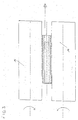
- Fig. 1 is a glow plug for a in a sectional view ceramic glow plug, which has an electrically conductive Inner cylinder 1, a coaxial with the inner cylinder 1 on the cylinder outer surface provided insulating layer 2, a coaxial with it provided conductive layer 3 and heating layers 4 and 5 having, as a coaxial layer 4 and perpendicular to the glow pin axis extending layer 5 at the end of the arrangement of inner cylinder 1 and layers 2, 3 are formed.
- the inner cylinder for example, by uniaxial Dry presses optionally with cold isostatic densification, formed by extrusion or by powder injection molding.
- the inner cylinder is then debinded and presintered or densely sintered, to give him sufficient strength for the to give subsequent work.
- the outer layers are then by thermal Spraying applied to the inner cylinder 1.
- the conductive Inner cylinder 1 and the insulating layer 2 by the above-described Forming process and are the conductive Layer 3 and perpendicular to the glow pin axis Layer 5 and optionally the coaxial layer 4 formed thereon be thermally sprayed.
- leading inner cylinder 1, the insulating layer 2 and the conductive layer 3 through the to produce described shaping method and only the vertical extending to the glow pin axis layer 5 and possibly the coaxial Layer 4 by thermal spraying to form.
- the thermal spraying is preferably carried out after pre-sintering or sintering of the components.
- the atmospheric plasma spraying are suitable (APS), Vacuum Plasma Spraying (VPS) and High Speed Flame Spraying (HVOF).
- the layer to be sprayed is heated to the blank during spraying. If the surface roughness of the blank for sufficient adhesion the layer to be sprayed is insufficient, the surface becomes mechanically before coating or by another Roughened process. It can also be sprayed on a primer which can also serve to the thermal expansion coefficients the materials of the inner cylinder 1 and the individual layers 2, 3, 4, 5 adapt to each other.
- an insulating layer can also be thermally sprayed, so that this construction the Use of a glow plug with such a ceramic glow plug as an ion current measuring candle allows.
- the electrical functional layers can be pre-sintered Base cylinders are thermally sprayed, in In this case, the final compression only in a downstream Gas pressure sintering process is done.
- the ceramic Functional layers by means of a thermal process Spray applied to the sintered raw cylinder.
- the Layer structure is rotationally symmetric and is through contacted an outer pole and an inner pole.
- the hard machining of the glow plug can after presintering or sintering or after thermal spraying, for example through a simple and inexpensive pass-through grinding process take place, as shown in Fig. 3.
- the glow plug is ground to its final geometry, which means Pinch roller 15 and a grinding wheel 16 takes place.
- the movement and direction of rotation of the tools and the machined Glow pin are shown in Fig. 3 by arrows.
- the inner cylinder 1 and the layers 2 to 5 are particularly suitable silicidic, carbidic, nitridic or boridic materials.
- sintering additives for example, oxides such as Al 2 O 3 and Y 2 O 3 and, in general, oxides of rare earth metals can be used.
- the thermal spray powder both as a pure powder mixture as well as already sintered granules available.
- the necessary for the thermal spraying Melting phase can also be achieved by adding fusible semiconducting or metallic components such as silicon are generated.
- one with a fusible phase coated powder for thermal spraying used.
Landscapes
- Engineering & Computer Science (AREA)
- Chemical & Material Sciences (AREA)
- Manufacturing & Machinery (AREA)
- Ceramic Engineering (AREA)
- Mechanical Engineering (AREA)
- Combustion & Propulsion (AREA)
- General Engineering & Computer Science (AREA)
- Microelectronics & Electronic Packaging (AREA)
- Inorganic Chemistry (AREA)
- Materials Engineering (AREA)
- Structural Engineering (AREA)
- Organic Chemistry (AREA)
- Resistance Heating (AREA)
- Coating By Spraying Or Casting (AREA)
- Spark Plugs (AREA)
Abstract
Description
Claims (10)
- Verfahren zum Herstellen eines Glühstiftes für eine keramische Glühkerze, der aus einem Innenzylinder und wenigstens einer Außenschicht aufgebaut ist, dadurch gekennzeichnet, dass die wenigstens eine Außenschicht durch thermisches Spritzen gebildet wird.
- Verfahren nach Anspruch 1, dadurch gekennzeichnet, dass die wenigstens eine Außenschicht eine zum Innenzylinder koaxiale Außenschicht ist.
- Verfahren nach Anspruch 1 oder 2, dadurch gekennzeichnet, dass die wenigstens eine Außenschicht eine den Innenzylinder stirnseitig bedeckende Schicht ist.
- Verfahren nach einem der Ansprüche 1 bis 3, dadurch gekennzeichnet, dass die thermischen Ausdehnungskoeffizienten des Materials des Innenzylinders und der Schichtmaterialien dadurch aneinander angepasst werden, dass Zwischenschichten mit entsprechenden Ausdehnungskoeffizienten thermisch aufgespritzt werden.
- Verfahren nach einem der Ansprüche 1 bis 4, dadurch gekennzeichnet, dass die Oberfläche, auf die wenigstens eine Außenschicht gespritzt wird, vor dem Spritzen aufgeraut wird.
- Verfahren nach einem der vorhergehenden Ansprüche, dadurch gekennzeichnet, dass die wenigstens eine Außenschicht durch Aufsprühen, Spritzen oder Pressen bzw. im Tauchverfahren gebildet wird.
- Verfahren nach Anspruch 1, dadurch gekennzeichnet, dass das thermische Spritzen auf einem Stab erfolgt, der aus dem Innenzylinder und wenigstens einer dazu koaxialen Schicht aufgebaut ist, wobei die koaxiale Schicht elektrisch isolierend oder leitend sein kann und der Stab durch Koextrusion gebildet wird.
- Verfahren nach einem der vorhergehenden Ansprüche, dadurch gekennzeichnet, dass der Innenzylinder vorgesintert wird und die Endverdichtung nach dem thermischen Spritzen der wenigstens einen Außenschicht durch Gasdrucksintern erfolgt.
- Verfahren nach Anspruch 7, dadurch gekennzeichnet, dass der Stab dichtgesintert wird und nach dem thermischen Spritzen auf den dichtgesinterten Stab eine thermische Behandlung zur Beseitigung der Restporösität der wenigstens einen thermisch gespritzten Schicht erfolgt.
- Verfahren nach einem der vorhergehenden Ansprüche, dadurch gekennzeichnet, dass der Glühstift vorwiegend aus Siliciden, Nitriden, Karbiden oder Boriden gebildet wird.
Applications Claiming Priority (2)
| Application Number | Priority Date | Filing Date | Title |
|---|---|---|---|
| DE10353973 | 2003-11-19 | ||
| DE10353973A DE10353973B4 (de) | 2003-11-19 | 2003-11-19 | Verfahren zum Herstellen eines keramischen Glühstiftes für eine keramische Glühkerze |
Publications (2)
| Publication Number | Publication Date |
|---|---|
| EP1536180A1 true EP1536180A1 (de) | 2005-06-01 |
| EP1536180B1 EP1536180B1 (de) | 2007-12-12 |
Family
ID=34442266
Family Applications (1)
| Application Number | Title | Priority Date | Filing Date |
|---|---|---|---|
| EP04023483A Expired - Lifetime EP1536180B1 (de) | 2003-11-19 | 2004-10-01 | Verfahren zum Herstellen eines Glühstiftes für eine keramische Glühkerze |
Country Status (7)
| Country | Link |
|---|---|
| US (1) | US20050118346A1 (de) |
| EP (1) | EP1536180B1 (de) |
| JP (1) | JP2005147655A (de) |
| KR (1) | KR101158299B1 (de) |
| AT (1) | ATE380982T1 (de) |
| DE (2) | DE10353973B4 (de) |
| ES (1) | ES2294418T3 (de) |
Cited By (2)
| Publication number | Priority date | Publication date | Assignee | Title |
|---|---|---|---|---|
| EP1533571A3 (de) * | 2003-11-19 | 2008-01-02 | Beru AG | Verfahren zum Herstellen von keramischen Glühkerzen |
| US9074574B2 (en) | 2011-11-11 | 2015-07-07 | Borgwarner Ludwigsburg Gmbh | Glow plug and method for producing a glow pencil |
Families Citing this family (4)
| Publication number | Priority date | Publication date | Assignee | Title |
|---|---|---|---|---|
| US7607206B2 (en) * | 2005-12-29 | 2009-10-27 | Federal Mogul World Wide, Inc. | Method for forming layered heating element for glow plug |
| DE102006044775A1 (de) * | 2006-09-22 | 2008-04-03 | Robert Bosch Gmbh | Verfahren und Vorrichtung zur Beschichtung eines Startelementes für Verbrennungsvorgänge in Brennkraftmaschinen |
| CN110314952B (zh) * | 2019-07-05 | 2021-01-15 | 徐州工程学院 | 一种轻质高强复合销轴的制备装置及方法 |
| FR3101475B1 (fr) * | 2019-09-26 | 2022-12-30 | Thermocoax Cie | « Câble à isolant minéral haute résistivité, et procédé de fabrication » |
Citations (7)
| Publication number | Priority date | Publication date | Assignee | Title |
|---|---|---|---|---|
| GB927336A (en) * | 1960-10-14 | 1963-05-29 | Wilkinson Sword Ltd | Improvements in or relating to igniting devices |
| DE2829028A1 (de) * | 1978-07-01 | 1980-01-10 | Bosch Gmbh Robert | Elektrischer widerstand |
| EP0262833A2 (de) * | 1986-09-22 | 1988-04-06 | Onoda Cement Company, Ltd. | Wärmefixierwalze zur Verwendung in einem Kopiergerät und Verfahren zu ihrer Herstellung |
| JPH02292172A (ja) * | 1989-04-28 | 1990-12-03 | Matsushita Electric Ind Co Ltd | セラミック部品の製造方法 |
| EP0918195A2 (de) * | 1997-11-21 | 1999-05-26 | Isuzu Ceramics Research Institute Co., Ltd. | Umhüllung |
| DE19908764A1 (de) * | 1998-02-20 | 1999-09-02 | Jidosha Kiki Co | Keramikheizeinsätze oder Keramikglühkerzen und Verfahren zu ihrer Herstellung |
| DE10029004A1 (de) * | 1999-06-16 | 2000-12-28 | Bosch Braking Systems Co | Keramikheizungs-Glühkerze |
Family Cites Families (24)
| Publication number | Priority date | Publication date | Assignee | Title |
|---|---|---|---|---|
| US3562371A (en) * | 1968-10-16 | 1971-02-09 | Corning Glass Works | High temperature gas isostatic pressing of crystalline bodies having impermeable surfaces |
| US4418661A (en) * | 1981-02-07 | 1983-12-06 | Robert Bosch Gmbh | Glow plug, particularly for diesel engine |
| JPS57199762A (en) * | 1981-06-02 | 1982-12-07 | Koutsu Seisakusho:Kk | Suction valve operation controller in automatic winder |
| JPS61217625A (ja) * | 1985-03-22 | 1986-09-27 | Jidosha Kiki Co Ltd | 自己温度制御型グロ−プラグ |
| JPS61217626A (ja) * | 1985-03-22 | 1986-09-27 | Jidosha Kiki Co Ltd | 自己温度制御型グロ−プラグ |
| JPS61252431A (ja) * | 1985-04-30 | 1986-11-10 | Kyocera Corp | セラミツク−金属接合部におけるシ−ル構造 |
| JPS62158926A (ja) * | 1985-12-28 | 1987-07-14 | Hitachi Metals Ltd | デイ−ゼルエンジン用グロ−プラグ |
| JPS62221536A (ja) * | 1986-03-24 | 1987-09-29 | 株式会社神戸製鋼所 | 複合部材及びその製造方法 |
| JPH01121626A (ja) * | 1987-11-05 | 1989-05-15 | Hitachi Metals Ltd | ディーゼルエンジン用グロープラグ |
| JP2773439B2 (ja) * | 1991-02-15 | 1998-07-09 | トヨタ自動車株式会社 | 炭化珪素含有窒化珪素複合体の製造方法 |
| JPH06144971A (ja) * | 1992-11-05 | 1994-05-24 | Chubu Sukegawa Kogyo Kk | セラミック積層体及びその製造方法 |
| US5338716A (en) * | 1992-12-01 | 1994-08-16 | Akzo Nobel Nv | Non-oxide metal ceramic catalysts comprising metal oxide support and intermediate ceramic passivating layer |
| US5391440A (en) * | 1994-02-14 | 1995-02-21 | Westinghouse Electric Corporation | Method of forming a leak proof plasma sprayed interconnection layer on an electrode of an electrochemical cell |
| US5578349A (en) * | 1995-11-30 | 1996-11-26 | Caterpillar Inc. | Process for coating a ceramic glow plug portion with a corrosion inhibiting material |
| JPH09159170A (ja) * | 1995-12-04 | 1997-06-20 | Tokyo Gas Co Ltd | セラミックグロープラグ |
| DK0812856T3 (da) * | 1996-06-14 | 2000-01-03 | Takeda Chemical Industries Ltd | Fremgangsmåde til fjernelse af N-terminalt methionin |
| JP3162324B2 (ja) * | 1997-09-02 | 2001-04-25 | 日本特殊陶業株式会社 | セラミックヒータ及び酸素センサ |
| JP3001857B1 (ja) * | 1998-07-31 | 2000-01-24 | 株式会社ジャパンエナジー | 耐低温酸化特性に優れた電極部を有するMoSi2を主体とする発熱材料 |
| DE19857958A1 (de) * | 1998-12-16 | 2000-06-21 | Bosch Gmbh Robert | Verfahren zur Herstellung eines Stiftheizer |
| DE19930334C2 (de) * | 1999-07-02 | 2003-07-31 | Beru Ag | Keramischer Heizstab und diesen enthaltende Glühkerze und Verfahren zu dessen Herstellung |
| DE10053327C2 (de) * | 2000-10-27 | 2003-04-10 | Bosch Gmbh Robert | Stiftheizer |
| US6610964B2 (en) * | 2001-03-08 | 2003-08-26 | Stephen J. Radmacher | Multi-layer ceramic heater |
| US6396028B1 (en) * | 2001-03-08 | 2002-05-28 | Stephen J. Radmacher | Multi-layer ceramic heater |
| DE10353972B4 (de) * | 2003-11-19 | 2006-03-16 | Beru Ag | Verfahren zum Herstellen von keramischen Glühkerzen |
-
2003
- 2003-11-19 DE DE10353973A patent/DE10353973B4/de not_active Expired - Fee Related
-
2004
- 2004-10-01 DE DE502004005694T patent/DE502004005694D1/de not_active Expired - Lifetime
- 2004-10-01 ES ES04023483T patent/ES2294418T3/es not_active Expired - Lifetime
- 2004-10-01 EP EP04023483A patent/EP1536180B1/de not_active Expired - Lifetime
- 2004-10-01 AT AT04023483T patent/ATE380982T1/de active
- 2004-11-10 US US10/984,882 patent/US20050118346A1/en not_active Abandoned
- 2004-11-12 KR KR1020040092199A patent/KR101158299B1/ko not_active Expired - Fee Related
- 2004-11-15 JP JP2004330066A patent/JP2005147655A/ja active Pending
Patent Citations (7)
| Publication number | Priority date | Publication date | Assignee | Title |
|---|---|---|---|---|
| GB927336A (en) * | 1960-10-14 | 1963-05-29 | Wilkinson Sword Ltd | Improvements in or relating to igniting devices |
| DE2829028A1 (de) * | 1978-07-01 | 1980-01-10 | Bosch Gmbh Robert | Elektrischer widerstand |
| EP0262833A2 (de) * | 1986-09-22 | 1988-04-06 | Onoda Cement Company, Ltd. | Wärmefixierwalze zur Verwendung in einem Kopiergerät und Verfahren zu ihrer Herstellung |
| JPH02292172A (ja) * | 1989-04-28 | 1990-12-03 | Matsushita Electric Ind Co Ltd | セラミック部品の製造方法 |
| EP0918195A2 (de) * | 1997-11-21 | 1999-05-26 | Isuzu Ceramics Research Institute Co., Ltd. | Umhüllung |
| DE19908764A1 (de) * | 1998-02-20 | 1999-09-02 | Jidosha Kiki Co | Keramikheizeinsätze oder Keramikglühkerzen und Verfahren zu ihrer Herstellung |
| DE10029004A1 (de) * | 1999-06-16 | 2000-12-28 | Bosch Braking Systems Co | Keramikheizungs-Glühkerze |
Non-Patent Citations (1)
| Title |
|---|
| PATENT ABSTRACTS OF JAPAN vol. 015, no. 065 (M - 1082) 15 February 1991 (1991-02-15) * |
Cited By (2)
| Publication number | Priority date | Publication date | Assignee | Title |
|---|---|---|---|---|
| EP1533571A3 (de) * | 2003-11-19 | 2008-01-02 | Beru AG | Verfahren zum Herstellen von keramischen Glühkerzen |
| US9074574B2 (en) | 2011-11-11 | 2015-07-07 | Borgwarner Ludwigsburg Gmbh | Glow plug and method for producing a glow pencil |
Also Published As
| Publication number | Publication date |
|---|---|
| EP1536180B1 (de) | 2007-12-12 |
| KR20050048474A (ko) | 2005-05-24 |
| JP2005147655A (ja) | 2005-06-09 |
| DE502004005694D1 (de) | 2008-01-24 |
| DE10353973A1 (de) | 2005-06-02 |
| US20050118346A1 (en) | 2005-06-02 |
| ATE380982T1 (de) | 2007-12-15 |
| KR101158299B1 (ko) | 2012-06-26 |
| ES2294418T3 (es) | 2008-04-01 |
| DE10353973B4 (de) | 2006-08-17 |
Similar Documents
| Publication | Publication Date | Title |
|---|---|---|
| DE69720651T2 (de) | Herstellungsverfahren eines keramischen Heizelment | |
| EP1533571B1 (de) | Verfahren zum Herstellen von keramischen Glühkerzen | |
| DE102015115746B4 (de) | Verfahren zum Herstellen einer Zündelektrode für Zündkerzen und damit hergestellte Zündkerze | |
| DE102015100441A1 (de) | Struktur oder Bauteil für Hochtemperaturanwendungen sowie Verfahren und Vorrichtung zur Herstellung derselben | |
| DE19857958A1 (de) | Verfahren zur Herstellung eines Stiftheizer | |
| DE10255859A1 (de) | Verfahren zur Herstellung einer keramischen Heizvorrichtung und Verfahren zur Herstellung einer Zündkerze | |
| EP2003753B1 (de) | Zündkerze und Verfahren zur Herstellung einer Zündkerze | |
| DE10353973B4 (de) | Verfahren zum Herstellen eines keramischen Glühstiftes für eine keramische Glühkerze | |
| EP0860043B1 (de) | Verfahen zur bescichtung und herstellung einer elektrode für zündkerzen für brennkraftmaschinen | |
| EP1305858B1 (de) | Zündkerze für einen verbrennungsmotor und verfahren zur herstellung einer zündkerze | |
| DE3320557C2 (de) | Verfahren zur Herstellung der Kühlwand einer Raketenbrennkammer und Verwendung derselben | |
| EP1299641A1 (de) | Glühstiftkerze mit ionenstromsensor sowie verfahren zum betreiben einer derartigen glühstiftkerze | |
| EP3601629B1 (de) | Kolbenring mit kugelgestrahlter einlaufschicht und verfahren zur herstellung | |
| EP2180967A1 (de) | Verfahren zur herstellung eines maschinengehäuses mit oberflächengehärteter fluidkammer | |
| EP1596968A2 (de) | Mehrlagiger keramikverbund | |
| DE3050181A1 (en) | Method for manufacturing a hollow glass punch for piece molding | |
| DE102020119424B4 (de) | Verfahren zum Herstellen einer Zündkerze | |
| EP1295067B1 (de) | Glühstiftkerze | |
| DE10248781B3 (de) | Verfahren zur Herstellung isolierter Körper | |
| WO2002002993A1 (de) | Glühstiftkerze mit ionenstromsensor sowie verfahren zum betreiben einer derartigen glühstiftkerze | |
| DE102020209100A1 (de) | Verfahren zur Herstellung von Sandkernen, die für Gießereizwecke einsetzbar sind | |
| DE102021128646B3 (de) | Verfahren zur Herstellung einer mineralisolierten Buchse | |
| DE2056235C3 (de) | Spulen-Zündanlage zum Betrieb von Brennkraftmaschinen, mit in ihre Hochspannungsleitungen eingeschalteten Vorfunkenstrecken | |
| EP1411218A2 (de) | Verfahren zur Herstellung isolierter Körper | |
| DE102021006599A1 (de) | Verfahren zur Herstellung einer mineralisolierten Buchse |
Legal Events
| Date | Code | Title | Description |
|---|---|---|---|
| PUAI | Public reference made under article 153(3) epc to a published international application that has entered the european phase |
Free format text: ORIGINAL CODE: 0009012 |
|
| AK | Designated contracting states |
Kind code of ref document: A1 Designated state(s): AT BE BG CH CY CZ DE DK EE ES FI FR GB GR HU IE IT LI LU MC NL PL PT RO SE SI SK TR |
|
| AX | Request for extension of the european patent |
Extension state: AL HR LT LV MK |
|
| 17P | Request for examination filed |
Effective date: 20050706 |
|
| AKX | Designation fees paid |
Designated state(s): AT BE BG CH CY CZ DE DK EE ES FI FR GB GR HU IE IT LI LU MC NL PL PT RO SE SI SK TR |
|
| GRAP | Despatch of communication of intention to grant a patent |
Free format text: ORIGINAL CODE: EPIDOSNIGR1 |
|
| GRAS | Grant fee paid |
Free format text: ORIGINAL CODE: EPIDOSNIGR3 |
|
| GRAA | (expected) grant |
Free format text: ORIGINAL CODE: 0009210 |
|
| AK | Designated contracting states |
Kind code of ref document: B1 Designated state(s): AT BE BG CH CY CZ DE DK EE ES FI FR GB GR HU IE IT LI LU MC NL PL PT RO SE SI SK TR |
|
| REG | Reference to a national code |
Ref country code: GB Ref legal event code: FG4D Free format text: NOT ENGLISH |
|
| REG | Reference to a national code |
Ref country code: CH Ref legal event code: EP |
|
| REG | Reference to a national code |
Ref country code: IE Ref legal event code: FG4D Free format text: LANGUAGE OF EP DOCUMENT: GERMAN |
|
| REF | Corresponds to: |
Ref document number: 502004005694 Country of ref document: DE Date of ref document: 20080124 Kind code of ref document: P |
|
| REG | Reference to a national code |
Ref country code: SE Ref legal event code: TRGR |
|
| REG | Reference to a national code |
Ref country code: ES Ref legal event code: FG2A Ref document number: 2294418 Country of ref document: ES Kind code of ref document: T3 |
|
| PG25 | Lapsed in a contracting state [announced via postgrant information from national office to epo] |
Ref country code: PL Free format text: LAPSE BECAUSE OF FAILURE TO SUBMIT A TRANSLATION OF THE DESCRIPTION OR TO PAY THE FEE WITHIN THE PRESCRIBED TIME-LIMIT Effective date: 20071212 Ref country code: FI Free format text: LAPSE BECAUSE OF FAILURE TO SUBMIT A TRANSLATION OF THE DESCRIPTION OR TO PAY THE FEE WITHIN THE PRESCRIBED TIME-LIMIT Effective date: 20071212 Ref country code: SI Free format text: LAPSE BECAUSE OF FAILURE TO SUBMIT A TRANSLATION OF THE DESCRIPTION OR TO PAY THE FEE WITHIN THE PRESCRIBED TIME-LIMIT Effective date: 20071212 Ref country code: NL Free format text: LAPSE BECAUSE OF FAILURE TO SUBMIT A TRANSLATION OF THE DESCRIPTION OR TO PAY THE FEE WITHIN THE PRESCRIBED TIME-LIMIT Effective date: 20071212 |
|
| NLV1 | Nl: lapsed or annulled due to failure to fulfill the requirements of art. 29p and 29m of the patents act | ||
| PG25 | Lapsed in a contracting state [announced via postgrant information from national office to epo] |
Ref country code: CZ Free format text: LAPSE BECAUSE OF FAILURE TO SUBMIT A TRANSLATION OF THE DESCRIPTION OR TO PAY THE FEE WITHIN THE PRESCRIBED TIME-LIMIT Effective date: 20071212 |
|
| ET | Fr: translation filed | ||
| PG25 | Lapsed in a contracting state [announced via postgrant information from national office to epo] |
Ref country code: RO Free format text: LAPSE BECAUSE OF FAILURE TO SUBMIT A TRANSLATION OF THE DESCRIPTION OR TO PAY THE FEE WITHIN THE PRESCRIBED TIME-LIMIT Effective date: 20071212 Ref country code: SK Free format text: LAPSE BECAUSE OF FAILURE TO SUBMIT A TRANSLATION OF THE DESCRIPTION OR TO PAY THE FEE WITHIN THE PRESCRIBED TIME-LIMIT Effective date: 20071212 |
|
| PG25 | Lapsed in a contracting state [announced via postgrant information from national office to epo] |
Ref country code: PT Free format text: LAPSE BECAUSE OF FAILURE TO SUBMIT A TRANSLATION OF THE DESCRIPTION OR TO PAY THE FEE WITHIN THE PRESCRIBED TIME-LIMIT Effective date: 20080512 |
|
| REG | Reference to a national code |
Ref country code: IE Ref legal event code: FD4D |
|
| PLBE | No opposition filed within time limit |
Free format text: ORIGINAL CODE: 0009261 |
|
| STAA | Information on the status of an ep patent application or granted ep patent |
Free format text: STATUS: NO OPPOSITION FILED WITHIN TIME LIMIT |
|
| PG25 | Lapsed in a contracting state [announced via postgrant information from national office to epo] |
Ref country code: IE Free format text: LAPSE BECAUSE OF FAILURE TO SUBMIT A TRANSLATION OF THE DESCRIPTION OR TO PAY THE FEE WITHIN THE PRESCRIBED TIME-LIMIT Effective date: 20071212 Ref country code: DK Free format text: LAPSE BECAUSE OF FAILURE TO SUBMIT A TRANSLATION OF THE DESCRIPTION OR TO PAY THE FEE WITHIN THE PRESCRIBED TIME-LIMIT Effective date: 20071212 |
|
| 26N | No opposition filed |
Effective date: 20080915 |
|
| PG25 | Lapsed in a contracting state [announced via postgrant information from national office to epo] |
Ref country code: GR Free format text: LAPSE BECAUSE OF FAILURE TO SUBMIT A TRANSLATION OF THE DESCRIPTION OR TO PAY THE FEE WITHIN THE PRESCRIBED TIME-LIMIT Effective date: 20080313 |
|
| BERE | Be: lapsed |
Owner name: BERU A.G. Effective date: 20081031 |
|
| PG25 | Lapsed in a contracting state [announced via postgrant information from national office to epo] |
Ref country code: EE Free format text: LAPSE BECAUSE OF FAILURE TO SUBMIT A TRANSLATION OF THE DESCRIPTION OR TO PAY THE FEE WITHIN THE PRESCRIBED TIME-LIMIT Effective date: 20071212 Ref country code: BG Free format text: LAPSE BECAUSE OF FAILURE TO SUBMIT A TRANSLATION OF THE DESCRIPTION OR TO PAY THE FEE WITHIN THE PRESCRIBED TIME-LIMIT Effective date: 20080312 |
|
| PG25 | Lapsed in a contracting state [announced via postgrant information from national office to epo] |
Ref country code: MC Free format text: LAPSE BECAUSE OF NON-PAYMENT OF DUE FEES Effective date: 20081031 |
|
| REG | Reference to a national code |
Ref country code: CH Ref legal event code: PL |
|
| PG25 | Lapsed in a contracting state [announced via postgrant information from national office to epo] |
Ref country code: CY Free format text: LAPSE BECAUSE OF FAILURE TO SUBMIT A TRANSLATION OF THE DESCRIPTION OR TO PAY THE FEE WITHIN THE PRESCRIBED TIME-LIMIT Effective date: 20071212 |
|
| PG25 | Lapsed in a contracting state [announced via postgrant information from national office to epo] |
Ref country code: BE Free format text: LAPSE BECAUSE OF NON-PAYMENT OF DUE FEES Effective date: 20081031 |
|
| PG25 | Lapsed in a contracting state [announced via postgrant information from national office to epo] |
Ref country code: CH Free format text: LAPSE BECAUSE OF NON-PAYMENT OF DUE FEES Effective date: 20081031 Ref country code: LI Free format text: LAPSE BECAUSE OF NON-PAYMENT OF DUE FEES Effective date: 20081031 |
|
| PG25 | Lapsed in a contracting state [announced via postgrant information from national office to epo] |
Ref country code: HU Free format text: LAPSE BECAUSE OF FAILURE TO SUBMIT A TRANSLATION OF THE DESCRIPTION OR TO PAY THE FEE WITHIN THE PRESCRIBED TIME-LIMIT Effective date: 20080613 Ref country code: LU Free format text: LAPSE BECAUSE OF NON-PAYMENT OF DUE FEES Effective date: 20081001 |
|
| PG25 | Lapsed in a contracting state [announced via postgrant information from national office to epo] |
Ref country code: TR Free format text: LAPSE BECAUSE OF FAILURE TO SUBMIT A TRANSLATION OF THE DESCRIPTION OR TO PAY THE FEE WITHIN THE PRESCRIBED TIME-LIMIT Effective date: 20071212 |
|
| PGFP | Annual fee paid to national office [announced via postgrant information from national office to epo] |
Ref country code: AT Payment date: 20101011 Year of fee payment: 7 |
|
| PGFP | Annual fee paid to national office [announced via postgrant information from national office to epo] |
Ref country code: GB Payment date: 20101012 Year of fee payment: 7 Ref country code: IT Payment date: 20101025 Year of fee payment: 7 |
|
| PGFP | Annual fee paid to national office [announced via postgrant information from national office to epo] |
Ref country code: SE Payment date: 20111017 Year of fee payment: 8 Ref country code: FR Payment date: 20111020 Year of fee payment: 8 Ref country code: ES Payment date: 20111028 Year of fee payment: 8 |
|
| REG | Reference to a national code |
Ref country code: AT Ref legal event code: MM01 Ref document number: 380982 Country of ref document: AT Kind code of ref document: T Effective date: 20121001 |
|
| GBPC | Gb: european patent ceased through non-payment of renewal fee |
Effective date: 20121001 |
|
| REG | Reference to a national code |
Ref country code: FR Ref legal event code: ST Effective date: 20130628 |
|
| PG25 | Lapsed in a contracting state [announced via postgrant information from national office to epo] |
Ref country code: GB Free format text: LAPSE BECAUSE OF NON-PAYMENT OF DUE FEES Effective date: 20121001 Ref country code: SE Free format text: LAPSE BECAUSE OF NON-PAYMENT OF DUE FEES Effective date: 20121002 Ref country code: AT Free format text: LAPSE BECAUSE OF NON-PAYMENT OF DUE FEES Effective date: 20121001 |
|
| PG25 | Lapsed in a contracting state [announced via postgrant information from national office to epo] |
Ref country code: FR Free format text: LAPSE BECAUSE OF NON-PAYMENT OF DUE FEES Effective date: 20121031 Ref country code: IT Free format text: LAPSE BECAUSE OF NON-PAYMENT OF DUE FEES Effective date: 20121001 |
|
| REG | Reference to a national code |
Ref country code: DE Ref legal event code: R082 Ref document number: 502004005694 Country of ref document: DE Representative=s name: KOTITSCHKE & HEURUNG PARTNERSCHAFT MBB PATENT-, DE Ref country code: DE Ref legal event code: R082 Ref document number: 502004005694 Country of ref document: DE Representative=s name: KOTITSCHKE & HEURUNG PARTNERSCHAFT MBB, DE |
|
| REG | Reference to a national code |
Ref country code: ES Ref legal event code: FD2A Effective date: 20140116 |
|
| PGFP | Annual fee paid to national office [announced via postgrant information from national office to epo] |
Ref country code: DE Payment date: 20131029 Year of fee payment: 10 |
|
| PG25 | Lapsed in a contracting state [announced via postgrant information from national office to epo] |
Ref country code: ES Free format text: LAPSE BECAUSE OF NON-PAYMENT OF DUE FEES Effective date: 20121002 |
|
| REG | Reference to a national code |
Ref country code: DE Ref legal event code: R119 Ref document number: 502004005694 Country of ref document: DE |
|
| PG25 | Lapsed in a contracting state [announced via postgrant information from national office to epo] |
Ref country code: DE Free format text: LAPSE BECAUSE OF NON-PAYMENT OF DUE FEES Effective date: 20150501 |