EP1538080A1 - Dispositiv d'accrochage d'un turbopropulseur sous une voilure d'aeronef - Google Patents
Dispositiv d'accrochage d'un turbopropulseur sous une voilure d'aeronef Download PDFInfo
- Publication number
- EP1538080A1 EP1538080A1 EP04106154A EP04106154A EP1538080A1 EP 1538080 A1 EP1538080 A1 EP 1538080A1 EP 04106154 A EP04106154 A EP 04106154A EP 04106154 A EP04106154 A EP 04106154A EP 1538080 A1 EP1538080 A1 EP 1538080A1
- Authority
- EP
- European Patent Office
- Prior art keywords
- rigid
- box
- turboprop
- transverse
- engine according
- Prior art date
- Legal status (The legal status is an assumption and is not a legal conclusion. Google has not performed a legal analysis and makes no representation as to the accuracy of the status listed.)
- Granted
Links
Images

Classifications
-
- B—PERFORMING OPERATIONS; TRANSPORTING
- B64—AIRCRAFT; AVIATION; COSMONAUTICS
- B64D—EQUIPMENT FOR FITTING IN OR TO AIRCRAFT; FLIGHT SUITS; PARACHUTES; ARRANGEMENT OR MOUNTING OF POWER PLANTS OR PROPULSION TRANSMISSIONS IN AIRCRAFT
- B64D27/00—Arrangement or mounting of power plants in aircraft; Aircraft characterised by the type or position of power plants
- B64D27/02—Aircraft characterised by the type or position of power plants
- B64D27/10—Aircraft characterised by the type or position of power plants of gas-turbine type
- B64D27/12—Aircraft characterised by the type or position of power plants of gas-turbine type within, or attached to, wings
-
- B—PERFORMING OPERATIONS; TRANSPORTING
- B64—AIRCRAFT; AVIATION; COSMONAUTICS
- B64D—EQUIPMENT FOR FITTING IN OR TO AIRCRAFT; FLIGHT SUITS; PARACHUTES; ARRANGEMENT OR MOUNTING OF POWER PLANTS OR PROPULSION TRANSMISSIONS IN AIRCRAFT
- B64D27/00—Arrangement or mounting of power plants in aircraft; Aircraft characterised by the type or position of power plants
- B64D27/40—Arrangements for mounting power plants in aircraft
- B64D27/402—Arrangements for mounting power plants in aircraft comprising box like supporting frames, e.g. pylons or arrangements for embracing the power plant
Definitions
- the present invention relates to a device capable of ensuring the hanging or the suspension a turboprop engine under an aircraft wing.
- Such a device can be used on any type of aircraft with turboprops hanging on his sails.
- it is particularly suitable for equipping aircraft equipped turboprop engines capable of providing high power, exceeding 10000 horses.
- These devices are especially designed for allow the transmission to the wing of the efforts static and dynamic engines, such as that the weight, the thrust, or the different dynamic efforts.
- an attachment device having a rigid structure provided with a box under-wing, as well as one or more sections rigid front arranged successively forward in the longitudinal direction of the engine.
- the device can include two rigid sections before.
- each section rigid front has two spaced transverse frames from each other, and connected to each other by a plurality connecting rods, which together form transversal frames a structure called structure in latticework.
- the object of the invention is therefore to propose a suspension device of a turboprop engine under a aircraft wing, this device remedying at least partially to the disadvantages mentioned above relating to the achievements of the prior art.
- the purpose of the invention is to present an attachment device for high power turboprop, capable of meet the requirements for the resumption of engine torque generated during the operation of the turboprop, and the mass of this device and to the limitation of the displacement of the nozzle of this turboprop compared to the attachment device.
- the subject of the invention is a suspension device of a turboprop engine under a aircraft wing, the device comprising a rigid structure with a sub-wing box as well as at least one rigid section before, each rigid front section including two frames transverse spaced apart from each other.
- at least one rigid section before the rigid structure further comprises at least one box upper front connecting a top of the two transverse frames of the rigid front section.
- the shackling device according to the invention is advantageous in that its design also allows it to satisfy the criteria of mass and limitation of the movement of the engine nozzle.
- the faculty of easily resume the entire engine torque is particular provided by the possibility of designing the device so that the / the front boxes the upper and the sub-wing together form an ensemble having substantially of a geometric continuity, ensuring thus a continuity in the recovery of the efforts transiting in an upper part of the device.
- this continuity was impossible to obtain with the devices of the prior art, because of the obligatory passage of efforts between the front part and the back part of the rigid structure of device, namely between the lattice structure and the sub-wing box.
- the design of the attachment device according to the invention is advantageously widely adapted to allow a vertical implementation of the turboprop engine on this same device, this setting up can then be realized by bringing the turboprop from below, and vertically up to the device snap fastened.
- At least one rigid front of the rigid structure further comprises at least two lateral rods arranged on each side and on the other side of the upper front box, these connecting rods the two transverse frames of the rigid section before.
- This hybrid configuration with the times at least one upper front box and one plurality of lateral rods, of the type of those used in a conventional lattice structure, allows a very good recovery of the engine torque, in the extent that it is then more partially absorbed by the lateral rods provided for this purpose.
- the presence of the lateral rods in limited quantity does not cause increase significant of the overall mass of the device snap, and allows accessibility turboprop, particularly in view of mount conventional equipment.
- the lateral rods are indifferently articulated on solidary fittings transverse frames, or embedded in these same transversal frames.
- At least one rigid section before the rigid structure includes only four lateral rods arranged on each side on the other side of the upper front box.
- these connecting rods being intended in particular to resume the couple motor, they are therefore preferentially symmetrically with respect to a vertical plane passing through the longitudinal axis of the turboprop.
- At least one rigid section before the rigid structure further comprises at least two front side boxes arranged on both sides of the upper front box, these front side boxes connecting the two transverse frames of the rigid section before.
- a rigid section before the rigid structure includes only two front side boxes arranged on either side of the upper front box.
- the lateral front boxes being especially intended to take over the engine torque, so they are preferentially arranged symmetrically by relative to a vertical plane passing through the axis longitudinal turboprop.
- the device and more specifically its rigid structure, includes two rigid sections before having a common intermediate transverse frame.
- each rigid front section can include a single upper front box connecting the upper part of the two transverse frames of this same rigid section before.
- each upper front casing comprises a lower spar, an upper spar, two blanks lateral and a plurality of ribs transversal interiors connecting the spars and blanks.
- each Upper front box is made of titanium.
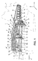
- this device 1 is intended to ensure the suspension of a turboprop 2 under an aircraft wing represented only schematically for obvious reasons of clarity, and generally designated by the reference number 4.
- the rigid structure 8 carries from behind to the front, successively along the longitudinal axis 5 of the turboprop 2, a sub-wing box rear 10, a first section before upper 12 and a second section before higher 14.
- the sub-wing box 10 is the same type than those encountered in devices turboprop coupling of the prior art, and well known to those skilled in the art.
- this box sub-wing 10 may comprise an upper spar 16 as well as a lower spar 18 extending each substantially in the X direction and substantially in XY planes, these beams 16 and 18 being connected between them through a plurality of transverse ribs spaced apart and arranged in YZ plans.
- the longitudinal members 16 and 18 are located in slightly inclined planes compared to XY plans.
- the spar upper 16 is arranged to approach the longitudinal axis 5 of the turboprop 2 extending towards the rear, while the lower spar 18 is arranged so as to move away from this longitudinal axis 5 extending backwards.
- transverse ribs 20 each take the form of a rectangle.
- the sub-wing box 10 comprises two side blanks closing the latter, each of these two blanks being optionally composed several flat and vertical blank portions.
- Sure Figure 1 only two portions of flan were represented for one of the two blanks of the sub-wing box 10, namely an upper front portion 22 and a lower front portion 24. The rear portions of this blank have been deliberately omitted for reasons clarity. Nevertheless, it is specified for information only that the front portions of blank 22 and 24 are located substantially in the same plane and preferably arranged so as to get closer to the axis longitudinal 5 of the turboprop 2 extending towards front, while the rear flan portions are also located substantially in the same plane, but preferably arranged so as to be closer to this longitudinal axis 5 extending rearwardly.
- each fastener 26 takes the form of a fitting extending upwards in a plane XZ from the upper spar 16, at the level of a lateral end thereof.
- a rear attachment 28 can also be provided to ensure the hooking of the device 1 under wing 4 together with the two fasteners before 26, this fastener 28 then taking the form of a fitting extending upwards in a YZ plane from the upper spar 16, at the level from a rear end of it.
- the sub-wing box 10 can be closed by a first transverse frame 30 located in a plane YZ, this first transverse frame 30 being preferably in the general U-shape returned, and also an integral part of the first stretch rigid before 12.
- the first framework transversal 30 carries a rear attachment intended for to allow the fixing of the turboprop 2 on the shackle 1, and therefore more specifically on its rigid structure 8.
- This rear attachment schematically represented and indicated by the numeral 31 in FIG. 1 is of the type classic, ie identical or similar to those encountered on the shackles of art prior. Therefore, no detailed description will not be made.
- the first rigid section before 12 comprises actually, in association with the first cadre transverse 30, a second transverse frame 32 also located in a YZ plane and U-shaped returned, his two branches going down and being located below its base.
- this U-shaped configuration returned was adopted in such a way that in a mounted state the turboprop 2 can be arranged between the two branches of each U.
- this rigid section 12 has a first upper front box 34 connecting a part upper two transverse frames 30 and 32, and more specifically the two U bases 30a and 32a returned trained respectively by these same frames 30 and 32. It is noted that in this first mode of preferred embodiment, a single box 34 connects the part upper two transverse frames 30 and 32. Nevertheless, without departing from the scope of the invention, it could naturally be provided several caissons before to connect the top of these two frames 30 and 32.
- the first upper front 34 is substantially parallelepipedic and extends substantially in the X direction.
- turboprop 2 it is nevertheless possible to provide that the first upper front box 34 is arranged so as to be slightly closer to the axis longitudinal 5 extending backwards, like this is visible in Figure 1.
- this box 34 is specially designed to take back the engine torque of the turboprop 2, it is preferably provided that a vertical plane (no represented) passing through the longitudinal axis 5 cuts the first front upper case 34 in two parts identical and symmetrical with respect to this same plane.
- a vertical plane (no represented) passing through the longitudinal axis 5 cuts the first front upper case 34 in two parts identical and symmetrical with respect to this same plane.
- the entire rigid structure 8 of the device 1 which is designed in such a way that the vertical plane passing through the longitudinal axis 5 delimits two identical and symmetrical parts of structure relative to this vertical plane.
- the first upper front box 34 is preferably kept solidarily on the frames transverse 30 and 32 by means of fittings 35 on which the box 34 is for example welded, these fittings 35 (only one of them being visible in Figure 1 because of the representation in perspective) being themselves preferably welded on U-shaped frames 30 and 32, close to intersections between branches and associated bases 30a and 32a of these U.
- fittings 35 could also be planned in a single block with the transverse frames 30 and 32, without leaving the frame of the invention.
- the first upper box 34 parallelepiped shaped comprises an upper spar 36 and a spar lower 38 each extending in planes slightly inclined parallel to planes XY, namely arranged so as to be closer to the longitudinal axis 5 of the turboprop 2 extending rearward.
- the beams 36 and 38 extend each substantially in the X direction and substantially in XY plans, without departing from the scope of the invention.
- the beams 36 and 38 are connected between them through a plurality of transverse ribs 40 spaced apart and arranged in planes YZ, these ribs 40 each taking the form of a rectangle.
- first front box upper 34 has two side blanks 42 and 44 extending into ZX planes, and also being integral with transverse ribs 40 located at inside a substantially parallelepiped space formed by the blanks 42,44 and the longitudinal members 36,38.
- the box 34 can be closed at its front and back ends by vertical walls in YZ planes, or simply be blanked respectively by the bases 30a and 32a of the transverse frames 30 and 32 on which this box 34 is mounted.
- all the elements components of the first upper front section 34 are made of titanium, or carbon.
- the frames transversals 30 and 32 are not only connected by the first upper front well 34 but also by through four connecting rods 46a, 46b, the number of these are obviously not under any circumstances limiting.
- the four links 46a, 46b are arranged symmetrically with respect to the vertical plane passing through the longitudinal axis 5 of the turboprop 2.
- a first connecting rod 46a is all first placed substantially in the direction X, and connected to a lower end of a branch of the U formed by the second cadre 32.
- this first connecting rod 46a can be arranged so that it constitutes an extension of the lower spar 18 of the box sub-wing 10.
- the rear end this rod 46a is preferably located substantially in the plane defined by the spar 18.
- the rear end of the connecting rod 46a and the lower beam 18 are connected successively the front to the back, by the transverse frame 30 and by a vertical blank 47 in the form of an integral square to the sub-wing box 10 as well as to the U-branch concerned, this blank 47 approaching the axis longitudinal 5 going backwards.
- this rod 46a is located preferably in a horizontal median plane (no represented) of the turboprop 2, passing through its axis longitudinal 5.
- a second rod 46b is also connected to the lower end of the same branch of the U formed by the second frame 32, the two rods 46a and 46b being in fact preferably connected to the same fitting 48.
- this second connecting rod 46b is not arranged according to the direction X, but is connected to the base 30a of the first frame transverse 30 U-shaped, or close to the intersection between the base and the relevant branch of this U.
- the second rod 46b is placed so to get closer to the vertical plane passing through the axis longitudinal 5, extending simultaneously towards back and up.
- "to the high meanans here in the Z direction, from turboprop 2 to the first front box higher 34.
- Two fittings 50 and 52 are also respectively provided on the first transverse frame 30 to ensure the mounting of the two connecting rods 46a and 46b.
- the four connecting rods 46a, 46b arranged symmetrically can be mounted articulated on their respective fittings 48, 50 and 52, or simply welded to them, so to obtain embedding.
- this structure rigid 8 also has a second rigid section before 14, substantially similar to the first section rigid 12 which has just been described.
- the second rigid section before 14 comprises the second transverse frame 32, and that a third transversal frame 54 also located in a YZ plane and U-shaped returned, both branches going down and being located in below its base, as is also the case for the other two frames 30 and 32.
- the third frame 54 substantially aligned with the other two being located at the front compared in the second frame 32, the latter then plays a role of middle manager jointly owned by both rigid sections before 12 and 14.
- This rigid section 14 has a second upper front box 56 connecting a part upper of the two transverse frames 32 and 54, and more specifically the two bases 32a and 54a of the U returned trained respectively by those same cadres 32 and 54.
- a single box 56 connects the part upper of the two transverse frames 32 and 54. Nevertheless, here too, it could be planned several front boxes to connect the upper part of these two frames 32 and 54, without departing from the invention.
- the second front box upper 56 is substantially parallelepipedal and substantially in the X direction. reasons for the turboprop 2, it is possible to nevertheless provide that the second upper front box 56 is arranged to approach slightly the longitudinal axis 5 extending forward, as this is visible in Figure 1.
- the vertical plane passing by the longitudinal axis 5 cuts this box 56 in two identical and symmetrical parts with respect to this same plan.
- the second upper front box 56 is preferably kept solidarily on the frames transversal 32 and 54 by means of fittings 57 on which the casing 56 is for example welded, these fittings 35 (only one of them being visible in Figure 1 because of the representation in perspective) being themselves preferably welded on the U-shaped frames 32 and 54, near the intersections between branches and associated bases 32a and 54a of these U.
- the second box before 56 in the form of parallelepiped comprises a upper spar 58 and a lower spar (not visible in Figure 1), each extending into parallel planes slightly inclined with respect to XY plans, namely arranged in such a way as to bring closer to the longitudinal axis 5 by extending towards forward.
- lower and upper side rails 58 each extend substantially in the X direction and substantially in XY planes, without departing from the invention.
- transverse ribs 60 spaced apart and arranged in planes YZ, these transverse ribs 60 each taking the shape of a rectangle.
- the second upper front box 56 has two side blanks 62 and 64 extending in ZX planes, and also being in solidarity with transverse ribs 60 located within a substantially parallelepipedic space formed by 64,64 blanks and the rails 58.
- the casing 56 can be closed at its front and back ends by vertical walls in YZ planes, or simply be plugged respectively by the bases 32a and 54a of the transverse frames 32 and 54 on which box 56 is mounted.
- all the elements components of the second upper front box 56 are made of titanium, or carbon.
- the transverse frames 32 and 54 are not only connected by the first box before higher 34 but also through four connecting rods 66a, 66b arranged in the same way that the connecting rods 46a, 46b of the first section 12.
- the four connecting rods 66a, 66b are arranged symmetrically with respect to the plane vertical axis passing through the longitudinal axis 5, and it is provided that on each side of the rigid structure 8 of the device 1, two connecting rods 66a, 66b together with the second caisson 56 the resumption of engine couple.
- a first connecting rod 66a is all first placed substantially in the direction X, and connected to a lower end of a branch of the U formed by the third cadre 54. Moreover, this first rod 66a can be arranged in the extension of the first connecting rod 46a of the first section 12, as is clear from the figure 1.
- a second connecting rod 66b is also connected to the lower end of the same branch of the U formed by the third frame 54, the two 66a and 66b connecting rods being in fact preferably connected to the same fitting 68.
- this second connecting rod 66b is not arranged according to the direction X, but is connected to the base 32a of the second frame transverse 32 U-shaped, or close to the intersection between the base and the relevant branch of this U.
- the second connecting rod 66b is placed so as to get closer to the vertical plane passing through the longitudinal axis 5, extending simultaneously backwards and upwards.
- "upwards" means here in the Z direction, from turboprop 2 to second upper front box 56.
- Two fittings 70 and 72 are also respectively provided on the second transverse frame 32 to assemble the rear ends of the two connecting rods 66a and 66b.
- the four rods 66a, 66b arranged symmetrically can be mounted in an articulated way on their respective fittings 68, 70 and 72, or simply welded to these, in order to obtain recesses.
- the third transverse frame 54 is provided of fasteners before 74 for fixing turboprop 2 on the attachment device 1, and therefore more specifically on its rigid structure 8.
- the fasteners before 74 are generally distributed around a gear reducer turboprop 2.
- latching device 100 With reference to Figure 3, we see a latching device 100 according to a second mode of preferred embodiment of the present invention, this device 100 being intended to ensure the suspension a turboprop engine under an aircraft wing (no represented in this figure).
- the attachment device 100 has a structure rigid 108 substantially similar to the rigid structure 8 of the attachment device 1 according to the first mode of preferred embodiment of the present invention.
- the elements of Figures 1 to 3 carrying the same numerical references correspond to elements identical or similar.
- the rigid structure 108 has a back forward, successively along the longitudinal axis turboprop, a sub-wing subwoofer 10 similar to that described above, a first section rigid before 112, as well as a second rigid section before 114.
- the first rigid section before 112 comprises the first transversal frame 30, the second frame transverse 32, and the first upper front box 34 connecting the upper portion 30a, 32a of the two frames 30 and 32.
- the first front box 34 differs slightly from that described in first preferred embodiment, insofar as it has a slightly trapezoidal shape in view from above, its rear end being more flared than its front end.
- each front attachment 26 and its rib 113 associated can be made in one piece.
- transverse frames 30 and 32 are not only connected by the first front box higher 34 but also through two front side boxes 76, the number of these being obviously in no way limiting.
- the two lateral front boxes 76 are arranged symmetrically with respect to the vertical plane passing through the longitudinal axis of the turboprop. By therefore, on each side of the rigid structure 108 of the device 100, a single lateral box 76 ensures together with the first caisson 34 the resumption of engine couple.
- the side casing 76 of shape substantially parallelepipedic and design identical or similar to that of the front boxes above 34 and 56 described above, is placed substantially in the X direction, and connected to a lower end of a branch of the U formed by the second frame 32, as well as at a lower end a branch of the U formed by the first frame 30.
- the geometric continuity can in particular be obtained by providing an external side blank (not referenced) of the casing 76 concerned is in the extension of a vertical side blank (no referenced) of the sub-wing box 10, as is clearly visible in Figure 3. It is specified in as an indication that unlike the sub wing box back of the first preferred embodiment, the box 10 of Figure 3 has on each side a single side vertical side, approaching the axis longitudinal turboprop engine going towards the rear.
- the second rigid section before 114 includes the second transverse frame 32, the third transverse frame 54, and the second front box upper 56 connecting the upper portion 32a, 54a of the two frames 32 and 54.
- the transverse frames 32 and 54 are no only connected by the second upper front box 56, but also through two caissons front side 78. Indeed, the two front boxes lateral 78 are arranged symmetrically with respect to the vertical plane passing through the longitudinal axis of turboprop. Therefore, on each side of the rigid structure 108 of the device 100, a single side box 78 jointly with the second box 56 the recovery of the engine torque.
- the lateral box 78 of substantially parallelepiped shape and design identical or similar to that of the front boxes above 34 and 56 described above, is placed substantially in the X direction. On the other hand, it is connected to a lower end of a branch of the U formed by the second frame 32, as well as at one end lower part of a U-shaped branch formed by the third frame 54.
Landscapes
- Engineering & Computer Science (AREA)
- Aviation & Aerospace Engineering (AREA)
- Structures Of Non-Positive Displacement Pumps (AREA)
- Supercharger (AREA)
- Body Structure For Vehicles (AREA)
- Filling Or Discharging Of Gas Storage Vessels (AREA)
- Vibration Prevention Devices (AREA)
Abstract
Description
- la figure 1 représente une vue en perspective de la structure rigide d'un dispositif d'accrochage d'un turbopropulseur, selon un premier mode de réalisation préféré de la présente invention ;
- la figure 2 représente une vue en coupe prise selon le plan P de la figure 1 ; et
- la figure 3 représente une vue en perspective de la structure rigide d'un dispositif d'accrochage d'un turbopropulseur, selon un second mode de réalisation préféré de la présente invention.
Claims (11)
- Dispositif d'accrochage (1,100) d'un turbopropulseur (2) sous une voilure (4) d'aéronef, ledit dispositif comportant une structure rigide (8,108) pourvue d'un caisson sous-aile arrière (10) ainsi que d'au moins un tronçon rigide avant (12,14,112,114), chaque tronçon rigide avant comportant notamment deux cadres transversaux (30,32,54) espacés l'un de l'autre, caractérisé en ce qu'au moins un tronçon rigide avant (12,14,112,114) de la structure rigide (8,108) comprend en outre au moins un caisson avant supérieur (34,56) reliant une partie supérieure (30a,32a,54a) des deux cadres transversaux (30,32,54) dudit tronçon rigide avant.
- Dispositif d'accrochage (1) d'un turbopropulseur selon la revendication 1, caractérisé en ce qu'au moins un tronçon rigide avant (12,14) de la structure rigide (8) comprend de plus au moins deux bielles latérales (46a,46b,66a,66b) agencées de part et d'autre du caisson avant supérieur (34,56), lesdites au moins deux bielles (46a,46b,66a,66b) reliant les deux cadres transversaux (30,32,54) dudit tronçon rigide avant.
- Dispositif d'accrochage (1) d'un turbopropulseur selon la revendication 2, caractérisé en ce que lesdites bielles latérales (46a,46b,66a,66b) sont articulées sur des ferrures (48,50,52,68,70,72) solidaires des cadres transversaux (30,32,54).
- Dispositif d'accrochage (1) d'un turbopropulseur selon la revendication 2, caractérisé en ce que lesdites bielles latérales (46a,46b,66a,66b) sont encastrées dans les cadres transversaux (30, 32, 54 ).
- Dispositif d'accrochage (1) d'un turbopropulseur selon l'une quelconque des revendications 2 à 4, caractérisé en ce qu'au moins un tronçon rigide avant (12,14) de la structure rigide (8) comprend uniquement quatre bielles latérales (46a,46b,66a,66b) agencées de part et d'autre du caisson avant supérieur (34,56).
- Dispositif d'accrochage (100) d'un turbopropulseur selon la revendication 1, caractérisé en ce qu'au moins un tronçon rigide avant (112, 114) de la structure rigide (108) comprend de plus au moins deux caissons avant latéraux (76,78) agencés de part et d'autre du caisson avant supérieur (34,56), lesdits au moins deux caissons avant latéraux (76,78) reliant les deux cadres transversaux (30,32,54) dudit tronçon rigide avant.
- Dispositif d'accrochage (100) d'un turbopropulseur selon la revendication 6, caractérisé en ce qu'au moins un tronçon rigide avant (112, 114) de la structure rigide (108) comprend uniquement deux caissons avant latéraux (76,78) agencés de part et d'autre du caisson avant supérieur (34,56).
- Dispositif d'accrochage (1,100) d'un turbopropulseur selon l'une quelconque des revendications précédentes, caractérisé en ce qu'il comprend deux tronçons rigides avant (12,14,112,114) disposant d'un cadre transversal intermédiaire commun (32).
- Dispositif d'accrochage (1,100) d'un turbopropulseur selon l'une quelconque des revendications précédentes, caractérisé en ce que chaque tronçon rigide avant (12,14,112,114) comporte un unique caisson avant supérieur (34,56) reliant la partie supérieure (30a,32a,54a) des deux cadres transversaux (30,32,54) dudit tronçon rigide avant.
- Dispositif d'accrochage (1,100) d'un turbopropulseur selon l'une quelconque des revendications précédentes, caractérisé en ce que chaque caisson avant supérieur (34,56) comporte un longeron inférieur (38), un longeron supérieur (36,58), deux flans latéraux (42,44,62,64), ainsi qu'une pluralité de nervures intérieures transversales (40,60) reliant lesdits longerons ainsi que lesdits flans latéraux.
- Dispositif d'accrochage (1,100) d'un turbopropulseur selon l'une quelconque des revendications précédentes, caractérisé en ce que chaque caisson avant supérieur (34,56) est réalisé en titane.
Applications Claiming Priority (2)
| Application Number | Priority Date | Filing Date | Title |
|---|---|---|---|
| FR0350946 | 2003-12-01 | ||
| FR0350946A FR2862944B1 (fr) | 2003-12-01 | 2003-12-01 | Dispositif d'accrochage d'un turbopropulseur sous une voilure d'aeronef |
Publications (2)
| Publication Number | Publication Date |
|---|---|
| EP1538080A1 true EP1538080A1 (fr) | 2005-06-08 |
| EP1538080B1 EP1538080B1 (fr) | 2006-06-21 |
Family
ID=34451760
Family Applications (1)
| Application Number | Title | Priority Date | Filing Date |
|---|---|---|---|
| EP04106154A Expired - Lifetime EP1538080B1 (fr) | 2003-12-01 | 2004-11-29 | Dispositiv d'accrochage d'un turbopropulseur sous une voilure d'aeronef |
Country Status (7)
| Country | Link |
|---|---|
| US (1) | US7159819B2 (fr) |
| EP (1) | EP1538080B1 (fr) |
| AT (1) | ATE330844T1 (fr) |
| CA (1) | CA2487841C (fr) |
| DE (1) | DE602004001319T2 (fr) |
| ES (1) | ES2266996T3 (fr) |
| FR (1) | FR2862944B1 (fr) |
Cited By (11)
| Publication number | Priority date | Publication date | Assignee | Title |
|---|---|---|---|---|
| FR2891252A1 (fr) * | 2005-09-28 | 2007-03-30 | Airbus France Sas | Mat a ossature monolithique |
| FR2900907A1 (fr) * | 2006-05-09 | 2007-11-16 | Airbus France Sas | Ensemble moteur pour aeronef a nacelle et mat integres |
| FR2909973A1 (fr) * | 2006-12-13 | 2008-06-20 | Airbus France Sa | Mat d'accrochage de turboreacteur pour aeronef a structure arriere de largeur transversale reduite |
| FR2915178A1 (fr) * | 2007-04-23 | 2008-10-24 | Airbus France Sa | Attache d'un caisson de mat sur une voilure, pincant un panneau lateral du caisson |
| FR2934565A1 (fr) * | 2008-08-04 | 2010-02-05 | Airbus France | Systeme d'attache d'un moteur sur une structure d'un aeronef tel qu'une aile volante. |
| FR2934845A1 (fr) * | 2008-08-11 | 2010-02-12 | Airbus France | Mat de moteur pour aeronef |
| FR2965547A1 (fr) * | 2010-10-01 | 2012-04-06 | Airbus Operations Sas | Structure rigide de mat d'accrochage d'un moteur d'aeronef comprenant un caisson en materiau composite renforce par des nervures transversales exterieures |
| WO2014174222A1 (fr) * | 2013-04-26 | 2014-10-30 | Snecma | Structure de suspension d'un turbopropulseur a double helices non carenees sur un element structurel d'un aeronef |
| WO2015104494A1 (fr) * | 2014-01-10 | 2015-07-16 | Snecma | Structure de suspension d'un turbopropulseur a double hélices non carénées sur un élément structurel d'un aéronef a fixation rigide de la structure d'entrée d'air |
| FR3054202A1 (fr) * | 2016-07-25 | 2018-01-26 | Safran Aircraft Engines | Berceau pour turbopropulseur a manche d'entree d'air integree |
| US10266273B2 (en) | 2013-07-26 | 2019-04-23 | Mra Systems, Llc | Aircraft engine pylon |
Families Citing this family (25)
| Publication number | Priority date | Publication date | Assignee | Title |
|---|---|---|---|---|
| FR2862944B1 (fr) * | 2003-12-01 | 2006-02-24 | Airbus France | Dispositif d'accrochage d'un turbopropulseur sous une voilure d'aeronef |
| FR2870821B1 (fr) * | 2004-05-25 | 2007-08-17 | Airbus France Sas | Aeronef comprenant un dispositif de detection et/ou de mesure de perturbations atmospheriques |
| US20060145001A1 (en) * | 2004-12-30 | 2006-07-06 | Smith Matthew C | Fan cowl door elimination |
| FR2885877B1 (fr) * | 2005-05-23 | 2008-12-12 | Airbus France Sas | Mat d'accrochage de turboreacteur pour aeronef |
| FR2887851B1 (fr) | 2005-06-29 | 2007-08-17 | Airbus France Sas | Mat d'accrochage de moteur pour aeronef |
| FR2891526B1 (fr) * | 2005-10-03 | 2007-11-02 | Airbus France Sas | Mat d'accrochage de turboreacteur pour aeronef |
| GB2434836B (en) * | 2006-02-04 | 2008-12-10 | Rolls Royce Plc | Mounting system for use in mounting a gas turbine engine |
| FR2916736B1 (fr) * | 2007-06-04 | 2009-09-04 | Airbus France Sa | Dispositif d'accrochage d'un turbopropulseur d'aeronef comprenant des moyens de fixation hydrauliques. |
| FR2920409B1 (fr) * | 2007-08-27 | 2009-12-18 | Airbus France | Berceau de support de capot de soufflante monte sur le mat d'accrochage et sur l'entree d'air de la nacelle |
| US8205825B2 (en) * | 2008-02-27 | 2012-06-26 | Spirit Aerosystems, Inc. | Engine pylon made from composite material |
| FR2929245B1 (fr) * | 2008-03-28 | 2010-05-14 | Aircelle Sa | Structure primaire d'un mat d'accrochage. |
| FR2976914B1 (fr) * | 2011-06-23 | 2014-12-26 | Snecma | Structure d'accrochage d'une turbomachine |
| BR112016010876B1 (pt) | 2013-11-18 | 2022-02-01 | Lord Corporation | Sistema de fixação de motor e método de fixação de um motor turboélice |
| FR3013678B1 (fr) * | 2013-11-25 | 2015-11-20 | Airbus Operations Sas | Carenage aerodynamique |
| US9238511B2 (en) | 2014-03-04 | 2016-01-19 | Mra Systems, Inc. | Engine pylon structure |
| FR3058704B1 (fr) * | 2016-11-14 | 2018-11-16 | Safran Aircraft Engines | Berceau bipartite a coulissement pour turbopropulseur |
| FR3071820B1 (fr) * | 2017-10-03 | 2020-12-04 | Airbus Operations Sas | Ensemble moteur d'aeronef |
| FR3072945B1 (fr) * | 2017-10-27 | 2020-11-20 | Airbus Operations Sas | Structure primaire de mat de support d'un groupe propulseur d'aeronef comportant une partie inferieure en u obtenue de maniere monobloc ou par soudage |
| FR3079215B1 (fr) * | 2018-03-22 | 2020-11-20 | Airbus Operations Sas | Carenage avant d'un mat d'aeronef comprenant une coiffe mobile et aeronef equipe dudit carenage avant |
| US11635024B2 (en) | 2019-08-16 | 2023-04-25 | Pratt & Whitney Canada Corp. | Pusher turboprop powerplant installation |
| US11674414B2 (en) * | 2021-03-19 | 2023-06-13 | Pratt & Whitney Canada Corp. | Gas turbine engine and mount assembly therefor |
| US12415610B2 (en) * | 2022-05-13 | 2025-09-16 | The Boeing Company | Strut assembly and method for coupling an engine to a wing of an aircraft |
| CN116119023B (zh) * | 2023-04-17 | 2023-07-18 | 成都沃飞天驭科技有限公司 | 飞行器测试平台及其主框架、主框架的设计方法 |
| EP4488181A1 (fr) * | 2023-07-06 | 2025-01-08 | Airbus Operations (S.A.S.) | Système de propulsion pour aéronef comprenant un turboréacteur, un mât et une attache moteur |
| FR3164697A1 (fr) * | 2024-07-19 | 2026-01-23 | Airbus Operations (S.A.S.) | Mât réacteur comportant une structure primaire et une structure secondaire avant avec des moyens de fixation de l’une à l’autre |
Citations (4)
| Publication number | Priority date | Publication date | Assignee | Title |
|---|---|---|---|---|
| EP0437868A1 (fr) * | 1988-11-10 | 1991-07-24 | The Boeing Company | Appareil et procédé pour réduire le flottement d'une surface portante d'avion |
| US6095456A (en) * | 1996-12-23 | 2000-08-01 | The Boeing Company | Strut-wing interface having dual upper links |
| US6123293A (en) * | 1997-04-01 | 2000-09-26 | Deutsches Zentrum Fur Luft-Und Raumfahrt E.V. | Engine mount, particularly for a propeller-driven aircraft, comprising a tubular frame structure |
| US6126110A (en) * | 1997-12-22 | 2000-10-03 | Mcdonnell Douglas Corporation | Horizontally opposed trunnion forward engine mount system supported beneath a wing pylon |
Family Cites Families (40)
| Publication number | Priority date | Publication date | Assignee | Title |
|---|---|---|---|---|
| US1544358A (en) * | 1923-03-08 | 1925-06-30 | Thomas Morse Aircraft Corp | Engine mounting for airplanes |
| US1641306A (en) * | 1926-10-23 | 1927-09-06 | Oscar Silverstein | Engine mounting for aeroplanes |
| US1705492A (en) * | 1927-08-15 | 1929-03-19 | Noble Warren | Engine mount |
| US1860444A (en) * | 1930-07-22 | 1932-05-31 | Emma F Woolson | Internal combustion engine |
| US2234394A (en) * | 1938-02-14 | 1941-03-11 | Amiot Felix | Aerial navigation machine |
| US2343426A (en) * | 1942-01-29 | 1944-03-07 | United Aircraft Corp | Vibration suppressing engine mount |
| US2355370A (en) * | 1942-02-27 | 1944-08-08 | Christopher J Frey | Engine mount |
| US2359822A (en) * | 1943-10-06 | 1944-10-10 | Glenn L Martin Co | Engine mount |
| US2411562A (en) * | 1944-02-23 | 1946-11-26 | United Aircraft Corp | Segment type resilient engine mount |
| US2529958A (en) * | 1945-10-09 | 1950-11-14 | Bristol Aeroplane Co Ltd | Means for supporting gas-turbine power plants |
| US2539960A (en) * | 1946-05-22 | 1951-01-30 | Bristol Aeroplane Co Ltd | Mounting structure for gas-turbine power plants for aircraft |
| US2589539A (en) * | 1948-11-26 | 1952-03-18 | Horace R Childress | Aircraft engine mounting |
| US2591393A (en) * | 1949-10-04 | 1952-04-01 | United Aircraft Corp | Engine mount attachment |
| US2828607A (en) * | 1955-10-24 | 1958-04-01 | Gen Motors Corp | Dual engine support |
| US2965338A (en) * | 1956-04-09 | 1960-12-20 | Rolls Royce | Engine mounting |
| US3067968A (en) * | 1958-12-29 | 1962-12-11 | Heppenstall Charles William | Retractable jet engine noise suppressor |
| US2968920A (en) * | 1959-01-28 | 1961-01-24 | Gen Electric | Engine mounting arrangement |
| US3204717A (en) * | 1961-11-30 | 1965-09-07 | Ford Motor Co | Vehicle power plant and wheel suspension system |
| US3240454A (en) * | 1963-09-12 | 1966-03-15 | Alfred N Ormond | Space center omni-directional linear mounting apparatus |
| US3327971A (en) * | 1964-06-23 | 1967-06-27 | Rolls Royce | Mounting arrangement for lift engines |
| US3502287A (en) * | 1968-10-01 | 1970-03-24 | David B Lindsay | Aircraft engine mounting system |
| GB1516980A (en) * | 1974-12-24 | 1978-07-05 | Rolls Royce | Mounting ducted fan gas turbine engines on aircraft |
| US4437627A (en) * | 1982-03-12 | 1984-03-20 | The Boeing Company | Integrated power plant installation system |
| FR2599708A1 (fr) * | 1986-06-10 | 1987-12-11 | Snecma | Dispositif d'accrochage arriere de securite d'un turboreacteur sur un mat d'avion |
| US5054715A (en) * | 1988-11-10 | 1991-10-08 | The Boeing Company | Apparatus and methods for reducing aircraft lifting surface flutter |
| US5452575A (en) * | 1993-09-07 | 1995-09-26 | General Electric Company | Aircraft gas turbine engine thrust mount |
| US5524847A (en) * | 1993-09-07 | 1996-06-11 | United Technologies Corporation | Nacelle and mounting arrangement for an aircraft engine |
| GB2303884B (en) * | 1995-04-13 | 1999-07-14 | Rolls Royce Plc | A mounting for coupling a turbofan gas turbine engine to an aircraft structure |
| FR2738034B1 (fr) * | 1995-08-23 | 1997-09-19 | Snecma | Dispositif de suspension d'un turbopropulseur |
| FR2793768B1 (fr) * | 1999-05-17 | 2001-09-07 | Aerospatiale Airbus | Dispositif de montage sur un mat d'un ensemble propulsif d'aeronef et mat adapte a ce dispositif |
| US6330985B1 (en) * | 2000-06-30 | 2001-12-18 | General Electric Company | Link component for aircraft engine mounting systems |
| GB2375513B (en) * | 2001-05-19 | 2005-03-23 | Rolls Royce Plc | A mounting arrangement for a gas turbine engine |
| FR2830516B1 (fr) * | 2001-10-04 | 2004-01-02 | Snecma Moteurs | Suspension de turboreacteur |
| FR2851226B1 (fr) * | 2003-02-19 | 2005-05-20 | Snecma Moteurs | Structure porteuse pour un turbopropulseur et ensemble comportant une telle structure porteuse |
| FR2862610B1 (fr) * | 2003-11-25 | 2007-03-23 | Airbus France | Dispositif d'accrochage reliant un moteur et une voilure d'aeronef |
| FR2862612B1 (fr) * | 2003-11-25 | 2006-02-17 | Airbus France | Dispositif d'accrochage d'un moteur sous une voilure d'aeronef |
| FR2862611B1 (fr) * | 2003-11-25 | 2007-03-09 | Airbus France | Dispositif d'accrochage d'un moteur sous une voilure d'aeronef |
| FR2862944B1 (fr) * | 2003-12-01 | 2006-02-24 | Airbus France | Dispositif d'accrochage d'un turbopropulseur sous une voilure d'aeronef |
| FR2862945B1 (fr) * | 2003-12-01 | 2006-04-28 | Airbus France | Dispositif d'accrochage d'un turbopropulseur sous une voilure d'aeronef. |
| US7104306B2 (en) * | 2004-06-14 | 2006-09-12 | The Boeing Company | Cast unitized primary truss structure and method |
-
2003
- 2003-12-01 FR FR0350946A patent/FR2862944B1/fr not_active Expired - Fee Related
-
2004
- 2004-11-15 US US10/987,151 patent/US7159819B2/en not_active Expired - Lifetime
- 2004-11-17 CA CA2487841A patent/CA2487841C/fr not_active Expired - Fee Related
- 2004-11-29 EP EP04106154A patent/EP1538080B1/fr not_active Expired - Lifetime
- 2004-11-29 ES ES04106154T patent/ES2266996T3/es not_active Expired - Lifetime
- 2004-11-29 DE DE602004001319T patent/DE602004001319T2/de not_active Expired - Lifetime
- 2004-11-29 AT AT04106154T patent/ATE330844T1/de not_active IP Right Cessation
Patent Citations (4)
| Publication number | Priority date | Publication date | Assignee | Title |
|---|---|---|---|---|
| EP0437868A1 (fr) * | 1988-11-10 | 1991-07-24 | The Boeing Company | Appareil et procédé pour réduire le flottement d'une surface portante d'avion |
| US6095456A (en) * | 1996-12-23 | 2000-08-01 | The Boeing Company | Strut-wing interface having dual upper links |
| US6123293A (en) * | 1997-04-01 | 2000-09-26 | Deutsches Zentrum Fur Luft-Und Raumfahrt E.V. | Engine mount, particularly for a propeller-driven aircraft, comprising a tubular frame structure |
| US6126110A (en) * | 1997-12-22 | 2000-10-03 | Mcdonnell Douglas Corporation | Horizontally opposed trunnion forward engine mount system supported beneath a wing pylon |
Cited By (23)
| Publication number | Priority date | Publication date | Assignee | Title |
|---|---|---|---|---|
| FR2891252A1 (fr) * | 2005-09-28 | 2007-03-30 | Airbus France Sas | Mat a ossature monolithique |
| WO2007036516A1 (fr) * | 2005-09-28 | 2007-04-05 | Airbus France | Mât à ossature monolithique |
| FR2900907A1 (fr) * | 2006-05-09 | 2007-11-16 | Airbus France Sas | Ensemble moteur pour aeronef a nacelle et mat integres |
| FR2909973A1 (fr) * | 2006-12-13 | 2008-06-20 | Airbus France Sa | Mat d'accrochage de turboreacteur pour aeronef a structure arriere de largeur transversale reduite |
| US8167238B2 (en) | 2007-04-23 | 2012-05-01 | Airbus Operations | Pylon caisson attachment on a wing, gripping a lateral panel of the caisson |
| WO2008129042A1 (fr) * | 2007-04-23 | 2008-10-30 | Airbus France | Attache d'un caisson de mat sur une voilure, pinçant un panneau lateral du caisson |
| FR2915178A1 (fr) * | 2007-04-23 | 2008-10-24 | Airbus France Sa | Attache d'un caisson de mat sur une voilure, pincant un panneau lateral du caisson |
| FR2934565A1 (fr) * | 2008-08-04 | 2010-02-05 | Airbus France | Systeme d'attache d'un moteur sur une structure d'un aeronef tel qu'une aile volante. |
| US8196859B2 (en) | 2008-08-04 | 2012-06-12 | Airbus Operations Sas | System for attaching an engine to the structure of an aircraft, such as a sail wing aircraft |
| FR2934845A1 (fr) * | 2008-08-11 | 2010-02-12 | Airbus France | Mat de moteur pour aeronef |
| WO2010018323A1 (fr) * | 2008-08-11 | 2010-02-18 | Airbus Operations | Mât de moteur pour aéronef |
| FR2965547A1 (fr) * | 2010-10-01 | 2012-04-06 | Airbus Operations Sas | Structure rigide de mat d'accrochage d'un moteur d'aeronef comprenant un caisson en materiau composite renforce par des nervures transversales exterieures |
| FR3005033A1 (fr) * | 2013-04-26 | 2014-10-31 | Snecma | Structure de suspension d'un turbopropulseur a double helices non carenees sur un element structurel d'un aeronef |
| WO2014174222A1 (fr) * | 2013-04-26 | 2014-10-30 | Snecma | Structure de suspension d'un turbopropulseur a double helices non carenees sur un element structurel d'un aeronef |
| GB2527709A (en) * | 2013-04-26 | 2015-12-30 | Snecma | Structure for suspending a twin prop-fan engine from a structural element of an air-craft |
| US9637239B2 (en) | 2013-04-26 | 2017-05-02 | Snecma | Structure for suspending a turboprop having two unducted propellers on a structural element of an airplane |
| GB2527709B (en) * | 2013-04-26 | 2019-10-30 | Snecma | Structure for suspending a twin prop-fan engine from a structural element of an aircraft |
| US10266273B2 (en) | 2013-07-26 | 2019-04-23 | Mra Systems, Llc | Aircraft engine pylon |
| WO2015104494A1 (fr) * | 2014-01-10 | 2015-07-16 | Snecma | Structure de suspension d'un turbopropulseur a double hélices non carénées sur un élément structurel d'un aéronef a fixation rigide de la structure d'entrée d'air |
| US10106266B2 (en) | 2014-01-10 | 2018-10-23 | Safran Aircraft Engines | Suspension structure for suspending a turboprop having two unducted propellers from a structural element of an aircraft with rigid fastening of the air intake structure |
| FR3054202A1 (fr) * | 2016-07-25 | 2018-01-26 | Safran Aircraft Engines | Berceau pour turbopropulseur a manche d'entree d'air integree |
| WO2018020112A1 (fr) | 2016-07-25 | 2018-02-01 | Safran Aircraft Engines | Berceau pour turbopropulseur a manche d'entrée d'air intégrée |
| US10562638B2 (en) | 2016-07-25 | 2020-02-18 | Safran Aircfraft Engines | Cradle for a turbopropeller engine with integrated air inlet duct |
Also Published As
| Publication number | Publication date |
|---|---|
| FR2862944A1 (fr) | 2005-06-03 |
| EP1538080B1 (fr) | 2006-06-21 |
| ES2266996T3 (es) | 2007-03-01 |
| ATE330844T1 (de) | 2006-07-15 |
| US7159819B2 (en) | 2007-01-09 |
| DE602004001319D1 (de) | 2006-08-03 |
| DE602004001319T2 (de) | 2007-06-14 |
| CA2487841C (fr) | 2012-09-18 |
| US20050116093A1 (en) | 2005-06-02 |
| CA2487841A1 (fr) | 2005-06-01 |
| FR2862944B1 (fr) | 2006-02-24 |
Similar Documents
| Publication | Publication Date | Title |
|---|---|---|
| EP1538080A1 (fr) | Dispositiv d'accrochage d'un turbopropulseur sous une voilure d'aeronef | |
| EP1538081B1 (fr) | Dispositif d'accrochage d'un turbopropulseur sous une voilure d'aeronef | |
| CA2623760C (fr) | Ensemble moteur pour aeronef comprenant un moteur ainsi qu'un dispositif d'accrochage d'un tel moteur | |
| EP2139769B1 (fr) | Attache d'un caisson de mat sur une voilure, pinçant un panneau lateral du caisson | |
| CA2623797C (fr) | Ensemble pour aeronef comprenant un element de voilure ainsi qu'un mat d'accrochage | |
| EP1535838A1 (fr) | Disporstif d'accrochage d'un moteur sous une voilure d'aéronef | |
| CA2486500C (fr) | Dispositif d'accrochage reliant un moteur et une voilure d'aeronef | |
| FR2917713A1 (fr) | Dispositif d'accrochage de moteur d'aeronef et aeronef comportant au moins un tel dispositif. | |
| EP2426051A1 (fr) | Mât d'accrochage de turboréacteur pour aéronef comprenant des attaches voilure avant alignees | |
| EP1773660B1 (fr) | Ensemble moteur pour aeronef | |
| EP1773659B9 (fr) | Ensemble moteur pour aeronef | |
| FR2914908A1 (fr) | Dispositif d'accrochage de moteur d'aeronef et aeronef comportant au moins un tel dispositif. | |
| FR2891251A1 (fr) | Mat d'accrochage de moteur pour aeronef | |
| FR2891526A1 (fr) | Mat d'accrochage de turboreacteur pour aeronef | |
| FR2891247A1 (fr) | Ensemble pour aeronef comprenant un element de voilure ainsi qu'un mat d'accrochage | |
| EP3505448A1 (fr) | Ensemble pour aeronef comprenant une structure primaire de mat d'accrochage fixee a un caisson de voilure par des attaches presentant un encombrement reduit dans la zone de bord d'attaque | |
| FR3065442A1 (fr) | Ensemble moteur pour aeronef comprenant une attache moteur avant integree au caisson du mat d'accrochage | |
| EP1535839A1 (fr) | Dispositif d'accrochage d'un moteur sous une voilure d'aéronef | |
| FR2887522A1 (fr) | Ensemble pour aeronef comprenant un element de voilure ainsi qu'un mat d'accrochage | |
| FR2939100A1 (fr) | Ensemble moteur pour aeronef comprenant une structure rigide modulaire de mat d'accrochage |
Legal Events
| Date | Code | Title | Description |
|---|---|---|---|
| PUAI | Public reference made under article 153(3) epc to a published international application that has entered the european phase |
Free format text: ORIGINAL CODE: 0009012 |
|
| AK | Designated contracting states |
Kind code of ref document: A1 Designated state(s): AT BE BG CH CY CZ DE DK EE ES FI FR GB GR HU IE IS IT LI LU MC NL PL PT RO SE SI SK TR |
|
| AX | Request for extension of the european patent |
Extension state: AL HR LT LV MK YU |
|
| 17P | Request for examination filed |
Effective date: 20051121 |
|
| GRAP | Despatch of communication of intention to grant a patent |
Free format text: ORIGINAL CODE: EPIDOSNIGR1 |
|
| AKX | Designation fees paid |
Designated state(s): AT BE BG CH CY CZ DE DK EE ES FI FR GB GR HU IE IS IT LI LU MC NL PL PT RO SE SI SK TR |
|
| GRAS | Grant fee paid |
Free format text: ORIGINAL CODE: EPIDOSNIGR3 |
|
| GRAA | (expected) grant |
Free format text: ORIGINAL CODE: 0009210 |
|
| AK | Designated contracting states |
Kind code of ref document: B1 Designated state(s): AT BE BG CH CY CZ DE DK EE ES FI FR GB GR HU IE IS IT LI LU MC NL PL PT RO SE SI SK TR |
|
| PG25 | Lapsed in a contracting state [announced via postgrant information from national office to epo] |
Ref country code: CZ Free format text: LAPSE BECAUSE OF FAILURE TO SUBMIT A TRANSLATION OF THE DESCRIPTION OR TO PAY THE FEE WITHIN THE PRESCRIBED TIME-LIMIT Effective date: 20060621 Ref country code: NL Free format text: LAPSE BECAUSE OF FAILURE TO SUBMIT A TRANSLATION OF THE DESCRIPTION OR TO PAY THE FEE WITHIN THE PRESCRIBED TIME-LIMIT Effective date: 20060621 Ref country code: IT Free format text: LAPSE BECAUSE OF FAILURE TO SUBMIT A TRANSLATION OF THE DESCRIPTION OR TO PAY THE FEE WITHIN THE PRESCRIBED TIME-LIMIT;WARNING: LAPSES OF ITALIAN PATENTS WITH EFFECTIVE DATE BEFORE 2007 MAY HAVE OCCURRED AT ANY TIME BEFORE 2007. THE CORRECT EFFECTIVE DATE MAY BE DIFFERENT FROM THE ONE RECORDED. Effective date: 20060621 Ref country code: IE Free format text: LAPSE BECAUSE OF FAILURE TO SUBMIT A TRANSLATION OF THE DESCRIPTION OR TO PAY THE FEE WITHIN THE PRESCRIBED TIME-LIMIT Effective date: 20060621 Ref country code: FI Free format text: LAPSE BECAUSE OF FAILURE TO SUBMIT A TRANSLATION OF THE DESCRIPTION OR TO PAY THE FEE WITHIN THE PRESCRIBED TIME-LIMIT Effective date: 20060621 Ref country code: PL Free format text: LAPSE BECAUSE OF FAILURE TO SUBMIT A TRANSLATION OF THE DESCRIPTION OR TO PAY THE FEE WITHIN THE PRESCRIBED TIME-LIMIT Effective date: 20060621 Ref country code: SK Free format text: LAPSE BECAUSE OF FAILURE TO SUBMIT A TRANSLATION OF THE DESCRIPTION OR TO PAY THE FEE WITHIN THE PRESCRIBED TIME-LIMIT Effective date: 20060621 Ref country code: SI Free format text: LAPSE BECAUSE OF FAILURE TO SUBMIT A TRANSLATION OF THE DESCRIPTION OR TO PAY THE FEE WITHIN THE PRESCRIBED TIME-LIMIT Effective date: 20060621 Ref country code: RO Free format text: LAPSE BECAUSE OF FAILURE TO SUBMIT A TRANSLATION OF THE DESCRIPTION OR TO PAY THE FEE WITHIN THE PRESCRIBED TIME-LIMIT Effective date: 20060621 Ref country code: AT Free format text: LAPSE BECAUSE OF FAILURE TO SUBMIT A TRANSLATION OF THE DESCRIPTION OR TO PAY THE FEE WITHIN THE PRESCRIBED TIME-LIMIT Effective date: 20060621 |
|
| REG | Reference to a national code |
Ref country code: GB Ref legal event code: FG4D Free format text: NOT ENGLISH |
|
| REG | Reference to a national code |
Ref country code: CH Ref legal event code: EP |
|
| REG | Reference to a national code |
Ref country code: IE Ref legal event code: FG4D Free format text: LANGUAGE OF EP DOCUMENT: FRENCH |
|
| REF | Corresponds to: |
Ref document number: 602004001319 Country of ref document: DE Date of ref document: 20060803 Kind code of ref document: P |
|
| PG25 | Lapsed in a contracting state [announced via postgrant information from national office to epo] |
Ref country code: DK Free format text: LAPSE BECAUSE OF FAILURE TO SUBMIT A TRANSLATION OF THE DESCRIPTION OR TO PAY THE FEE WITHIN THE PRESCRIBED TIME-LIMIT Effective date: 20060921 |
|
| GBT | Gb: translation of ep patent filed (gb section 77(6)(a)/1977) |
Effective date: 20060911 |
|
| REG | Reference to a national code |
Ref country code: SE Ref legal event code: TRGR |
|
| PG25 | Lapsed in a contracting state [announced via postgrant information from national office to epo] |
Ref country code: PT Free format text: LAPSE BECAUSE OF FAILURE TO SUBMIT A TRANSLATION OF THE DESCRIPTION OR TO PAY THE FEE WITHIN THE PRESCRIBED TIME-LIMIT Effective date: 20061121 |
|
| PG25 | Lapsed in a contracting state [announced via postgrant information from national office to epo] |
Ref country code: MC Free format text: LAPSE BECAUSE OF NON-PAYMENT OF DUE FEES Effective date: 20061130 Ref country code: BE Free format text: LAPSE BECAUSE OF NON-PAYMENT OF DUE FEES Effective date: 20061130 |
|
| NLV1 | Nl: lapsed or annulled due to failure to fulfill the requirements of art. 29p and 29m of the patents act | ||
| REG | Reference to a national code |
Ref country code: IE Ref legal event code: FD4D |
|
| REG | Reference to a national code |
Ref country code: ES Ref legal event code: FG2A Ref document number: 2266996 Country of ref document: ES Kind code of ref document: T3 |
|
| PLBE | No opposition filed within time limit |
Free format text: ORIGINAL CODE: 0009261 |
|
| STAA | Information on the status of an ep patent application or granted ep patent |
Free format text: STATUS: NO OPPOSITION FILED WITHIN TIME LIMIT |
|
| 26N | No opposition filed |
Effective date: 20070322 |
|
| BERE | Be: lapsed |
Owner name: AIRBUS FRANCE Effective date: 20061130 |
|
| PG25 | Lapsed in a contracting state [announced via postgrant information from national office to epo] |
Ref country code: GR Free format text: LAPSE BECAUSE OF FAILURE TO SUBMIT A TRANSLATION OF THE DESCRIPTION OR TO PAY THE FEE WITHIN THE PRESCRIBED TIME-LIMIT Effective date: 20060922 |
|
| PG25 | Lapsed in a contracting state [announced via postgrant information from national office to epo] |
Ref country code: BG Free format text: LAPSE BECAUSE OF FAILURE TO SUBMIT A TRANSLATION OF THE DESCRIPTION OR TO PAY THE FEE WITHIN THE PRESCRIBED TIME-LIMIT Effective date: 20060921 Ref country code: EE Free format text: LAPSE BECAUSE OF FAILURE TO SUBMIT A TRANSLATION OF THE DESCRIPTION OR TO PAY THE FEE WITHIN THE PRESCRIBED TIME-LIMIT Effective date: 20060621 |
|
| PG25 | Lapsed in a contracting state [announced via postgrant information from national office to epo] |
Ref country code: TR Free format text: LAPSE BECAUSE OF FAILURE TO SUBMIT A TRANSLATION OF THE DESCRIPTION OR TO PAY THE FEE WITHIN THE PRESCRIBED TIME-LIMIT Effective date: 20060621 Ref country code: LU Free format text: LAPSE BECAUSE OF NON-PAYMENT OF DUE FEES Effective date: 20061129 Ref country code: HU Free format text: LAPSE BECAUSE OF FAILURE TO SUBMIT A TRANSLATION OF THE DESCRIPTION OR TO PAY THE FEE WITHIN THE PRESCRIBED TIME-LIMIT Effective date: 20061222 Ref country code: IS Free format text: LAPSE BECAUSE OF FAILURE TO SUBMIT A TRANSLATION OF THE DESCRIPTION OR TO PAY THE FEE WITHIN THE PRESCRIBED TIME-LIMIT Effective date: 20060621 |
|
| PG25 | Lapsed in a contracting state [announced via postgrant information from national office to epo] |
Ref country code: CY Free format text: LAPSE BECAUSE OF FAILURE TO SUBMIT A TRANSLATION OF THE DESCRIPTION OR TO PAY THE FEE WITHIN THE PRESCRIBED TIME-LIMIT Effective date: 20060621 |
|
| REG | Reference to a national code |
Ref country code: CH Ref legal event code: PL |
|
| PG25 | Lapsed in a contracting state [announced via postgrant information from national office to epo] |
Ref country code: LI Free format text: LAPSE BECAUSE OF NON-PAYMENT OF DUE FEES Effective date: 20081130 Ref country code: CH Free format text: LAPSE BECAUSE OF NON-PAYMENT OF DUE FEES Effective date: 20081130 |
|
| REG | Reference to a national code |
Ref country code: GB Ref legal event code: 732E Free format text: REGISTERED BETWEEN 20110721 AND 20110727 |
|
| REG | Reference to a national code |
Ref country code: FR Ref legal event code: CJ Effective date: 20110916 Ref country code: FR Ref legal event code: TP Owner name: AIRBUS HOLDING, FR Effective date: 20110913 Ref country code: FR Ref legal event code: CA Effective date: 20110916 Ref country code: FR Ref legal event code: CD Owner name: AIRBUS HOLDING, FR Effective date: 20110916 |
|
| REG | Reference to a national code |
Ref country code: ES Ref legal event code: PC2A Owner name: AIRBUS OPERATIONS SAS Effective date: 20120308 |
|
| REG | Reference to a national code |
Ref country code: DE Ref legal event code: R082 Ref document number: 602004001319 Country of ref document: DE Representative=s name: HENKEL, BREUER & PARTNER, DE |
|
| REG | Reference to a national code |
Ref country code: DE Ref legal event code: R082 Ref document number: 602004001319 Country of ref document: DE Representative=s name: PATENTANWAELTE HENKEL, BREUER & PARTNER, DE Effective date: 20120326 Ref country code: DE Ref legal event code: R081 Ref document number: 602004001319 Country of ref document: DE Owner name: AIRBUS OPERATIONS SAS, FR Free format text: FORMER OWNER: AIRBUS FRANCE, TOULOUSE, FR Effective date: 20120326 |
|
| PGFP | Annual fee paid to national office [announced via postgrant information from national office to epo] |
Ref country code: SE Payment date: 20121120 Year of fee payment: 9 Ref country code: ES Payment date: 20121127 Year of fee payment: 9 Ref country code: IT Payment date: 20121122 Year of fee payment: 9 |
|
| REG | Reference to a national code |
Ref country code: SE Ref legal event code: EUG |
|
| PG25 | Lapsed in a contracting state [announced via postgrant information from national office to epo] |
Ref country code: SE Free format text: LAPSE BECAUSE OF NON-PAYMENT OF DUE FEES Effective date: 20131130 Ref country code: IT Free format text: LAPSE BECAUSE OF NON-PAYMENT OF DUE FEES Effective date: 20131129 |
|
| REG | Reference to a national code |
Ref country code: ES Ref legal event code: FD2A Effective date: 20150504 |
|
| PG25 | Lapsed in a contracting state [announced via postgrant information from national office to epo] |
Ref country code: ES Free format text: LAPSE BECAUSE OF NON-PAYMENT OF DUE FEES Effective date: 20131130 |
|
| REG | Reference to a national code |
Ref country code: FR Ref legal event code: PLFP Year of fee payment: 12 |
|
| REG | Reference to a national code |
Ref country code: FR Ref legal event code: PLFP Year of fee payment: 13 |
|
| REG | Reference to a national code |
Ref country code: FR Ref legal event code: PLFP Year of fee payment: 14 |
|
| PGFP | Annual fee paid to national office [announced via postgrant information from national office to epo] |
Ref country code: DE Payment date: 20191121 Year of fee payment: 16 |
|
| PGFP | Annual fee paid to national office [announced via postgrant information from national office to epo] |
Ref country code: GB Payment date: 20191120 Year of fee payment: 16 |
|
| REG | Reference to a national code |
Ref country code: DE Ref legal event code: R119 Ref document number: 602004001319 Country of ref document: DE |
|
| GBPC | Gb: european patent ceased through non-payment of renewal fee |
Effective date: 20201129 |
|
| PG25 | Lapsed in a contracting state [announced via postgrant information from national office to epo] |
Ref country code: GB Free format text: LAPSE BECAUSE OF NON-PAYMENT OF DUE FEES Effective date: 20201129 Ref country code: DE Free format text: LAPSE BECAUSE OF NON-PAYMENT OF DUE FEES Effective date: 20210601 |
|
| PGFP | Annual fee paid to national office [announced via postgrant information from national office to epo] |
Ref country code: FR Payment date: 20231120 Year of fee payment: 20 |