EP1543250B1 - Integrierte öltransferhülse und lager - Google Patents
Integrierte öltransferhülse und lager Download PDFInfo
- Publication number
- EP1543250B1 EP1543250B1 EP03792054A EP03792054A EP1543250B1 EP 1543250 B1 EP1543250 B1 EP 1543250B1 EP 03792054 A EP03792054 A EP 03792054A EP 03792054 A EP03792054 A EP 03792054A EP 1543250 B1 EP1543250 B1 EP 1543250B1
- Authority
- EP
- European Patent Office
- Prior art keywords
- fluid
- assembly
- sleeve
- shaft
- roller bearing
- Prior art date
- Legal status (The legal status is an assumption and is not a legal conclusion. Google has not performed a legal analysis and makes no representation as to the accuracy of the status listed.)
- Expired - Lifetime
Links
- 239000012530 fluid Substances 0.000 claims abstract description 70
- 230000000712 assembly Effects 0.000 claims abstract description 6
- 238000000429 assembly Methods 0.000 claims abstract description 6
- 238000005461 lubrication Methods 0.000 claims description 9
- 230000003068 static effect Effects 0.000 claims description 5
- 238000001816 cooling Methods 0.000 claims description 2
- 238000005096 rolling process Methods 0.000 description 7
- 238000005452 bending Methods 0.000 description 5
- 230000001050 lubricating effect Effects 0.000 description 3
- 230000000717 retained effect Effects 0.000 description 2
- 238000009825 accumulation Methods 0.000 description 1
- 239000000969 carrier Substances 0.000 description 1
- 230000002028 premature Effects 0.000 description 1
- 239000013585 weight reducing agent Substances 0.000 description 1
Images


Classifications
-
- F—MECHANICAL ENGINEERING; LIGHTING; HEATING; WEAPONS; BLASTING
- F16—ENGINEERING ELEMENTS AND UNITS; GENERAL MEASURES FOR PRODUCING AND MAINTAINING EFFECTIVE FUNCTIONING OF MACHINES OR INSTALLATIONS; THERMAL INSULATION IN GENERAL
- F16C—SHAFTS; FLEXIBLE SHAFTS; ELEMENTS OR CRANKSHAFT MECHANISMS; ROTARY BODIES OTHER THAN GEARING ELEMENTS; BEARINGS
- F16C33/00—Parts of bearings; Special methods for making bearings or parts thereof
- F16C33/30—Parts of ball or roller bearings
- F16C33/66—Special parts or details in view of lubrication
- F16C33/6637—Special parts or details in view of lubrication with liquid lubricant
- F16C33/6659—Details of supply of the liquid to the bearing, e.g. passages or nozzles
- F16C33/6674—Details of supply of the liquid to the bearing, e.g. passages or nozzles related to the amount supplied, e.g. gaps to restrict flow of the liquid
-
- F—MECHANICAL ENGINEERING; LIGHTING; HEATING; WEAPONS; BLASTING
- F01—MACHINES OR ENGINES IN GENERAL; ENGINE PLANTS IN GENERAL; STEAM ENGINES
- F01D—NON-POSITIVE DISPLACEMENT MACHINES OR ENGINES, e.g. STEAM TURBINES
- F01D25/00—Component parts, details, or accessories, not provided for in, or of interest apart from, other groups
- F01D25/16—Arrangement of bearings; Supporting or mounting bearings in casings
- F01D25/162—Bearing supports
-
- F—MECHANICAL ENGINEERING; LIGHTING; HEATING; WEAPONS; BLASTING
- F01—MACHINES OR ENGINES IN GENERAL; ENGINE PLANTS IN GENERAL; STEAM ENGINES
- F01D—NON-POSITIVE DISPLACEMENT MACHINES OR ENGINES, e.g. STEAM TURBINES
- F01D25/00—Component parts, details, or accessories, not provided for in, or of interest apart from, other groups
- F01D25/18—Lubricating arrangements
-
- F—MECHANICAL ENGINEERING; LIGHTING; HEATING; WEAPONS; BLASTING
- F16—ENGINEERING ELEMENTS AND UNITS; GENERAL MEASURES FOR PRODUCING AND MAINTAINING EFFECTIVE FUNCTIONING OF MACHINES OR INSTALLATIONS; THERMAL INSULATION IN GENERAL
- F16C—SHAFTS; FLEXIBLE SHAFTS; ELEMENTS OR CRANKSHAFT MECHANISMS; ROTARY BODIES OTHER THAN GEARING ELEMENTS; BEARINGS
- F16C19/00—Bearings with rolling contact, for exclusively rotary movement
- F16C19/22—Bearings with rolling contact, for exclusively rotary movement with bearing rollers essentially of the same size in one or more circular rows, e.g. needle bearings
- F16C19/24—Bearings with rolling contact, for exclusively rotary movement with bearing rollers essentially of the same size in one or more circular rows, e.g. needle bearings for radial load mainly
- F16C19/28—Bearings with rolling contact, for exclusively rotary movement with bearing rollers essentially of the same size in one or more circular rows, e.g. needle bearings for radial load mainly with two or more rows of rollers
-
- F—MECHANICAL ENGINEERING; LIGHTING; HEATING; WEAPONS; BLASTING
- F16—ENGINEERING ELEMENTS AND UNITS; GENERAL MEASURES FOR PRODUCING AND MAINTAINING EFFECTIVE FUNCTIONING OF MACHINES OR INSTALLATIONS; THERMAL INSULATION IN GENERAL
- F16C—SHAFTS; FLEXIBLE SHAFTS; ELEMENTS OR CRANKSHAFT MECHANISMS; ROTARY BODIES OTHER THAN GEARING ELEMENTS; BEARINGS
- F16C33/00—Parts of bearings; Special methods for making bearings or parts thereof
- F16C33/30—Parts of ball or roller bearings
- F16C33/58—Raceways; Race rings
- F16C33/581—Raceways; Race rings integral with other parts, e.g. with housings or machine elements such as shafts or gear wheels
-
- F—MECHANICAL ENGINEERING; LIGHTING; HEATING; WEAPONS; BLASTING
- F16—ENGINEERING ELEMENTS AND UNITS; GENERAL MEASURES FOR PRODUCING AND MAINTAINING EFFECTIVE FUNCTIONING OF MACHINES OR INSTALLATIONS; THERMAL INSULATION IN GENERAL
- F16C—SHAFTS; FLEXIBLE SHAFTS; ELEMENTS OR CRANKSHAFT MECHANISMS; ROTARY BODIES OTHER THAN GEARING ELEMENTS; BEARINGS
- F16C33/00—Parts of bearings; Special methods for making bearings or parts thereof
- F16C33/30—Parts of ball or roller bearings
- F16C33/66—Special parts or details in view of lubrication
- F16C33/6637—Special parts or details in view of lubrication with liquid lubricant
- F16C33/664—Retaining the liquid in or near the bearing
- F16C33/6651—Retaining the liquid in or near the bearing in recesses or cavities provided in retainers, races or rolling elements
-
- F—MECHANICAL ENGINEERING; LIGHTING; HEATING; WEAPONS; BLASTING
- F16—ENGINEERING ELEMENTS AND UNITS; GENERAL MEASURES FOR PRODUCING AND MAINTAINING EFFECTIVE FUNCTIONING OF MACHINES OR INSTALLATIONS; THERMAL INSULATION IN GENERAL
- F16C—SHAFTS; FLEXIBLE SHAFTS; ELEMENTS OR CRANKSHAFT MECHANISMS; ROTARY BODIES OTHER THAN GEARING ELEMENTS; BEARINGS
- F16C2360/00—Engines or pumps
- F16C2360/23—Gas turbine engines
-
- F—MECHANICAL ENGINEERING; LIGHTING; HEATING; WEAPONS; BLASTING
- F16—ENGINEERING ELEMENTS AND UNITS; GENERAL MEASURES FOR PRODUCING AND MAINTAINING EFFECTIVE FUNCTIONING OF MACHINES OR INSTALLATIONS; THERMAL INSULATION IN GENERAL
- F16C—SHAFTS; FLEXIBLE SHAFTS; ELEMENTS OR CRANKSHAFT MECHANISMS; ROTARY BODIES OTHER THAN GEARING ELEMENTS; BEARINGS
- F16C2361/00—Apparatus or articles in engineering in general
- F16C2361/61—Toothed gear systems, e.g. support of pinion shafts
Definitions
- the present invention relates generally to a gas turbine engine reduction gearbox, and in particular, to an assembly comprising an integrated roller bearing and oil transfer sleeve for use in a gas turbine engine reduction gearbox.
- Reduction gearboxes of gas turbine engines especially those in acrobatic propeller-driven engines, experience considerable in-flight stresses resulting in significant bending of all rotating shafts within the gearbox.
- these gearboxes contain gears rotating at extremely high speeds, a constant supply of oil is required for cooling and lubrication of the components.
- an oil transfer sleeve 52 which aids distribution of oil within a gearbox 50, as shown in Fig. 1.
- a sleeve 52 generally receives oil from an outer chamber 54, and provides distribution of the oil to inner rotating elements such as the planetary carrier 56 and the planet gears 58.
- An oil film can be provided within the inner diameter of the oil transfer sleeve 52, creating a journal bearing for supporting the inner rotating shaft 60 of the planetary carrier 56, for example.
- Internal oil feed cavities 62 within the inner shaft 60 that is supported by the journal bearing can become pinched by bending forces, resulting in reduced oil flow to the rotating gears.
- Other known bearing assemblies are described in DE 3825456 A and US 5,076,766 .
- an assembly as claimed in claim 1 Preferably, the assembly of the present invention provides both direct rolling contact and hydrodynamic support for the rotary shaft.
- Fig. 1 is a cross-sectional view of a gas turbine engine planetary gearbox of the prior art having an transfer sleeve.
- Fig. 2 is a cross-sectional view of a gas turbine engine planetary gearbox comprising an integrated fluid transfer sleeve and roller bearing assembly according to a preferred embodiment of the present invention.
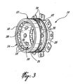
- Fig. 3 is a perspective view of the integrated fluid transfer sleeve and roller bearing according to a preferred embodiment of the present invention.
- Fig. 4a is a cross-sectional view of the integrated fluid transfer sleeve and roller bearing of Fig. 3.
- Fig. 4b is an enlarged cross-sectional view of the integrated fluid transfer sleeve and roller bearing of Fig.4a mounted on a shaft.
- Fig. 5 is an enlarged, partial cross-sectional view of the integrated fluid transfer sleeve and roller bearing assembly of the planetary gearbox shown in Fig. 2.
- the first reduction stage of a gas turbine engine reduction gearbox 11 having a gearbox casing 13 comprises a rotatable planetary carrier shaft 20 of the planetary carrier 15, planet gears 17, a central rotating sun gear 19, and an outer static ring gear 29.
- a fluid transfer sleeve assembly 10 according to a preferred embodiment of the present invention comprises bearing members 14 adapted to support the planetary carrier shaft 20 and provides lubricating fluid distribution to the rolling elements of the bearing members 14 and to other rotating parts of the gearbox such as the planet gears.
- the fluid transfer sleeve assembly 10 generally comprises an outer sleeve casing 12, defining a central annular fluid plenum 22, and having a bearing member 14 disposed at either end of the cylindrical sleeve casing.
- the bearing members 14 have no inner bearing races, and the bearing outer races 16 are integrally formed with the sleeve casing 12.
- the bearing members are preferably roller bearings, having a plurality of cylindrical roller elements 18 adapted to directly contact and support a centrally extending rotating shaft, such as the planetary carrier shaft 20 as shown in the gas turbine engine application depicted in greater detail in Fig. 4, which will be described in further detail below.
- the sleeve casing 12 comprises a plurality of radially extending flanges 30, circumferentially disposed about one end of the sleeve casing, adapted for engaging the fluid transfer sleeve assembly 10 to a static housing member.
- the central, radially innermost annular portion 38 of the sleeve casing separating the two roller bearing members 14 and forming an axially extending inner band partially defining the fluid plenum 22 radially outward therefrom, comprises a plurality of apertures 36 extending radially through the annular wall portion 38.
- the apertures 36 are depicted as circular holes in the figures, however it is to be understood that apertures of any shape could equivalently be used.
- the apertures preferably have an even circumferential spacing. Additionally, the number of apertures can be equivalently varied, depending on the size of each aperture.
- more numerous but smaller-sized apertures could be used; and these could be arrange in several rows or in another configuration adapted for best transmittal of the fluid to the shaft.
- the plurality of apertures 36 could actually be a single, annular slot formed in the central portion 38 of the sleeve casing.
- the apertures 36 ensure sufficient fluid flow communication between the fluid plenum 22 and an annular fluid leakage clearance 34, precisely defined between the inner circumferential surface 26 of the central portion 38 of the sleeve casing 12 and an outer circumferential surface 21 of a shaft 20 extending therethrough.
- the annular fluid leakage clearance 34 is formed as a result of the inner diameter 27 of the central portion 38 of the sleeve casing being slightly greater than the outer diameter 23 of the central shaft 20. This also eliminates any risk of the sleeve casing rubbing on the shaft, when the bearings must support high radially directed loads or shaft misalignment.
- the internal clearance of the bearing, the play between the shaft 20, the roller elements 18 and the outer ring casing 12, is preferably between 0.0005 and 0.0015 inch (0.01 to 0.04 mm).
- the apertures 36 ensure that lubrication fluid from the fluid plenum 22 can be fed, generally by pressure, into the thin annular fluid leakage clearance 34, creating a thin fluid film around the rotating shaft within the central inner portion 38 of the sleeve casing, creating a central hydrodynamically lubricated portion, disposed between the two outer direct contact rolling element bearings 14, that is similar to a standard journal bearing.
- the annular fluid leakage clearance is axially openended, such that continually fed fluid forced axially forward and backward lubricates the rolling elements 18 of the bearing members 14, such that there is significantly reduced bearing wear.
- the precise fluid leakage gap 34 is dimensioned to ensure adequate lubrication of rolling elements 18, adjacent the central annular fluid leakage gap at either end of the fluid transfer sleeve, and to maintain the lubricating fluid pressure in the fluid leakage clearance 34 such that the fluid is transferred from the static sleeve to rotating parts, such as to the planetary carrier shaft 20 and consequently also to other rotating elements of the planetary gear system.
- Two O-ring seals 28 are preferably located partially within the outer circumferential surface 24 of the sleeve casing 12, on either side of the fluid plenum 22.
- the seals 28 ensure that lubrication fluid is retained within the fluid plenum 22 when the fluid transfer sleeve assembly is disposed within an aperture of a surrounding housing.
- the only seals required by the preferred embodiment of the present invention are therefore only located on the outer circumferential surface 24 of the entire fluid transfer sleeve assembly 10. No seals are required to limit the axial fluid leakage away from the bearing sleeve assembly, thereby eliminating any seals that are required to be in continuous contact with the rotating part and which thereby causing undue premature wear.
- the controlled gap of the annular fluid leakage clearance 34 limits itself the outflow of lubrication fluid.
- the gas turbine engine reduction gearbox 11 comprises the fluid transfer sleeve assembly 10, located within the reduction gearbox casing 13 and retained thereto via threaded fasteners 32, used to fix the plurality of sleeve casing flanges 30 to the gearbox housing 13. This prevents any axial or rotary movement of the fluid transfer sleeve.
- a plurality of sleeve casing flanges 30 are depicted and described, a single radially extending flange having circumferentially spaced holes therein could equivalently be used.
- the multiple bearing flanges 30 are preferably used for reasons of weight reduction.
- the bearing flanges 30 also ensure perpendicularity of the roller bearing members 14 with the reduction gearbox housing 13.
- the roller elements 18 of the bearing members 14 are in direct rolling contact with the outer circumferential surface 21 of the rotating planetary carrier shaft 20, and therefore close tolerances of the sleeve casing 12 and the rolling elements 18 must be guaranteed.
- Low roller bearing maximum internal radial clearances and eccentricity with respect to the reduction gearbox housing must be maintained in order to ensure good overall performance.
- the thickness of the sleeve casing 12 joining the outer races 16 of the bearing members 14 can also be adjusted to ensure compliance with these tight tolerances required.
- the planetary carrier 15 generally comprises planet gears 17 supported by journal bearings, which are fed lubricating fluid from the annular fluid leakage clearance 34, via internal fluid passages 25 of the planetary shaft.
- a plurality of slots or holes 31 in the shaft 20 permit the pressurised lubrication fluid in the annular fluid leakage clearance 34 to be fed into the internal passages 25.
- the planet gears 17, supported by the planetary carrier 15 are driven by a central sun gear 19 and revolve within a radially outer static ring gear 29, thereby rotating the planetary carrier 15 whose shaft 20 is supported by the roller bearing members 14 integrally formed within the fluid transfer sleeve assembly 10.
Landscapes
- Engineering & Computer Science (AREA)
- General Engineering & Computer Science (AREA)
- Mechanical Engineering (AREA)
- Rolling Contact Bearings (AREA)
- Support Of The Bearing (AREA)
Claims (7)
- Anordnung mit einer integrierten Wälzlager- und Fluidtransferhülse (10) und mit einer drehbaren Welle (20), wobei die integrierte Wälzlager- und Fluidtransferhülse (10) zum Abstützen sowie zum Übertragen von Fluid zu der Welle (20) in einem Gasturbinenmaschinen-Untersetzungsgetriebe (11) ausgebildet ist, wobei die Anordnung Folgendes aufweist:eine Fluidtransferhülse mit einem Hülsengehäuse (12), in dem ein ringförmiges Fluidplenum (22) gebildet ist, das radial nach außen offen ist; undwenigstens zwei voneinander beabstandete Wälzlageranordnungen (14), von denen jede einen ringförmigen äußeren Lagerring (16) aufweist, der in integraler Weise mit dem Hülsengehäuse (12) ausgebildet ist, und von denen jede eine Mehrzahl von Wälzkörpern (18) aufweist, die durch den äußeren Lagerring abgestützt sind, wobei jede Wälzlageranordnung (14) innerhalb des Hülsengehäuses (12) angeordnet ist, und zwar je eine an einem der entgegengesetzten Enden von diesem;wobei die Anordnung dadurch gekennzeichnet ist,
dass die Mehrzahl der Wälzkörper (18) in jeder Wälzlageranordnung einen ersten Innendurchmesser (23) bildet, der im Wesentlichen gleich einem Au-ßendurchmesser (23) der von den Wälzkörperanordnungen (14) gelagerten Welle (20) ist;
dass das Hülsengehäuse (12) eine sich axial erstreckende Innenumfangsfläche (26) zwischen den Wälzlageranordnungen (14) aufweist und einen zweiten Innendurchmesser (27) bildet, der größer ist als der erste Innendurchmesser (23), so dass ein ringförmiger Fluidleckagefreiraum (34) zwischen der Innenumfangsfläche (26) des Hülsengehäuses (12) und einer Au-ßenumfangsfläche (21) der Welle (20) gebildet ist; und
dass mindestens eine Öffnung (36) in dem Hülsengehäuse (12) gebildet ist, die eine Fluidströmung von dem ringförmigen Fluidplenum (22) zu dem Fluidleckagefreiraum (34) ermöglicht,
so dass Fluid in dem Fluidleckagefreiraum (34) zu den Wälzkörpern (18) der Wälzlageranordnungen (14) und zu der Welle (20) transferiert werden kann. - Anordnung nach Anspruch 1,
wobei die Fluidtransferhülse Kühl- und Schmierfluid zu rotierenden Elementen des Getriebes (11) transferiert. - Anordnung nach Anspruch 1 oder 2,
wobei das Getriebe (11) ein Planetengetriebe ist. - Anordnung nach Anspruch 3,
wobei die Welle (20) eine Erststufen-Planetenträgerwelle des Planetengetriebes ist. - Anordnung nach einem der vorausgehenden Ansprüche,
wobei ein radial verlaufender Lagerflansch (30), der für die Befestigung an einem statischen Außengehäuse (13) ausgebildet ist, von dem Hülsengehäuse (12) wegragt, so dass die Fluidtransferhülse in dem Außengehäuse (13) axial festgelegt ist und in Bezug auf die Welle (20) rechtwinklig positioniert ist. - Anordnung nach einem der vorausgehenden Ansprüche,
wobei Dichtungen (28) auf einer Außenumfangsfläche (24) des Hülsengehäuses (12) vorgesehen sind, die beidseits des ringförmigen Fluidplenums (22) angeordnet sind. - Anordnung nach Anspruch 6,
wobei es sich bei den Dichtungen (28) um O-Ringe handelt.
Applications Claiming Priority (3)
| Application Number | Priority Date | Filing Date | Title |
|---|---|---|---|
| US226263 | 1981-01-19 | ||
| US10/226,263 US6758598B2 (en) | 2002-08-23 | 2002-08-23 | Integrated oil transfer sleeve and bearing |
| PCT/CA2003/001011 WO2004018886A1 (en) | 2002-08-23 | 2003-07-08 | Integrated oil transfer sleeve and bearing |
Publications (2)
| Publication Number | Publication Date |
|---|---|
| EP1543250A1 EP1543250A1 (de) | 2005-06-22 |
| EP1543250B1 true EP1543250B1 (de) | 2007-09-12 |
Family
ID=31887187
Family Applications (1)
| Application Number | Title | Priority Date | Filing Date |
|---|---|---|---|
| EP03792054A Expired - Lifetime EP1543250B1 (de) | 2002-08-23 | 2003-07-08 | Integrierte öltransferhülse und lager |
Country Status (5)
| Country | Link |
|---|---|
| US (1) | US6758598B2 (de) |
| EP (1) | EP1543250B1 (de) |
| CA (1) | CA2494737C (de) |
| DE (1) | DE60316320T2 (de) |
| WO (1) | WO2004018886A1 (de) |
Families Citing this family (32)
| Publication number | Priority date | Publication date | Assignee | Title |
|---|---|---|---|---|
| US20060193545A1 (en) * | 2005-02-25 | 2006-08-31 | Honeywell International Inc. | Rolling element bearing cage with improved pilot surface lubrication |
| FR2921973B1 (fr) * | 2007-10-04 | 2011-04-29 | Snecma | Carter intermediaire de turboreacteur et turboreacteur |
| US9121303B2 (en) * | 2008-06-10 | 2015-09-01 | United Technologies Corporation | Bearing system |
| US8065867B2 (en) * | 2008-06-20 | 2011-11-29 | United Technologies Corporation | Radial ball bearing |
| US20100092379A1 (en) * | 2008-10-13 | 2010-04-15 | Stewart Albert E | Apparatus and method for use in calcination |
| RU2484272C2 (ru) * | 2011-06-23 | 2013-06-10 | Открытое Акционерное общество "Научно-производственное предприятие "Мотор" | Опора роторов турбины высокотемпературного газотурбинного двигателя |
| US8414448B2 (en) * | 2011-08-31 | 2013-04-09 | General Electric Company | Gear system for wind turbine |
| US8771124B2 (en) | 2012-01-16 | 2014-07-08 | Hamilton Sundstrand Corporation | Carrier for planetary gear system |
| US8961112B2 (en) | 2012-03-26 | 2015-02-24 | United Technologies Corporation | Torque frame bushing arrangement for gas turbine engine fan drive gear system |
| EP2978954A4 (de) | 2013-03-28 | 2016-11-30 | United Technologies Corp | Hinterlagerhülse für ein gasturbinenhilfstriebwerk |
| US9695710B2 (en) | 2014-09-08 | 2017-07-04 | United Technologies Corporation | Oil transfer bearing |
| US9488061B2 (en) | 2014-10-01 | 2016-11-08 | Electro-Motive Diesel, Inc. | Compressor seal assembly for a turbocharger |
| US9803493B2 (en) | 2014-10-01 | 2017-10-31 | Electro-Motive Diesel, Inc. | Turbine bearing and seal assembly for a turbocharger |
| US10288163B2 (en) | 2015-10-23 | 2019-05-14 | General Electric Company | Method and system for a planetary power gearbox static to rotating oil transfer supply |
| EP3239481A1 (de) * | 2016-04-27 | 2017-11-01 | Rolls-Royce plc | Ölkammerwand mit durchgangsöffnungen |
| US10519809B2 (en) | 2016-10-21 | 2019-12-31 | Pratt & Whitney Canada Corp. | Liner for mounting socket of magnesium housing of aircraft engine |
| DE102017108332A1 (de) | 2017-04-19 | 2018-10-25 | Rolls-Royce Deutschland Ltd & Co Kg | Getriebevorrichtung mit wenigstens einem gegenüber einer Gehäuseeinrichtung drehenden Bauteil |
| CN109027010B (zh) * | 2018-09-10 | 2020-07-28 | 宁波艾德轴业有限公司 | 一种带齿轮的圆柱滚子轴承 |
| US11371441B2 (en) | 2019-06-07 | 2022-06-28 | Raytheon Technologies Corporation | Translating fluid delivery device |
| US11454320B2 (en) | 2020-04-27 | 2022-09-27 | Raytheon Technologies Corporation | Porous seal element with internal fluid passage |
| US11466778B2 (en) * | 2020-04-27 | 2022-10-11 | Raytheon Technologies Corporation | Rotational equipment seal element with internal fluid passage |
| US11339719B2 (en) | 2020-04-27 | 2022-05-24 | Raytheon Technologies Corporation | Fluid delivery system for rotational equipment |
| US11624439B2 (en) | 2020-04-27 | 2023-04-11 | Raytheon Technologies Corporation | Retainer for securing a seal element to a seal carrier |
| US11506080B2 (en) * | 2020-10-02 | 2022-11-22 | Pratt & Whitney Canada Corp. | Gas turbine engine probe cooling |
| CN112672628B (zh) * | 2020-12-30 | 2023-03-10 | 西安开容电子技术有限责任公司 | 一种转动机构的屏蔽装置 |
| FR3120915B1 (fr) | 2021-03-16 | 2023-04-14 | Safran Aircraft Engines | Module de soufflante equipe d’un dispositif de transfert d’huile |
| FR3120914B1 (fr) * | 2021-03-16 | 2025-03-07 | Safran Aircraft Engines | Module de soufflante equipe d’un dispositif de transfert d’huile |
| FR3120912B1 (fr) * | 2021-03-16 | 2023-02-24 | Safran Aircraft Engines | Module de soufflante equipe d’un dispositif de transfert d’huile |
| FR3120913B1 (fr) * | 2021-03-16 | 2023-02-24 | Safran Aircraft Engines | Module de soufflante equipe d’un dispositif de transfert d’huile |
| DE102021109637A1 (de) | 2021-04-16 | 2022-10-20 | Rolls-Royce Deutschland Ltd & Co Kg | Planetengetriebe für ein Gasturbinentriebwerk |
| US11788433B2 (en) * | 2021-10-26 | 2023-10-17 | Pratt & Whitney Canada Corp. | Lubrication system of aircraft engine |
| US12188551B1 (en) * | 2023-09-29 | 2025-01-07 | Rtx Corporation | Reduced clearance interface between a fluid device and a rotating structure for a geartrain |
Family Cites Families (13)
| Publication number | Priority date | Publication date | Assignee | Title |
|---|---|---|---|---|
| US2334775A (en) | 1941-04-25 | 1943-11-23 | Blakeslee & Co G S | Transmission unit |
| US2681126A (en) | 1950-03-31 | 1954-06-15 | Searls Edward Charles | Lubrication of gearing |
| US3305280A (en) | 1964-02-13 | 1967-02-21 | Bunting Brass & Bronze Co | Combination bearing |
| US3821908A (en) | 1972-12-12 | 1974-07-02 | Allis Chalmers | Retainer for planet pinion shaft |
| DE2848778A1 (de) | 1978-11-10 | 1980-05-22 | Kugelfischer G Schaefer & Co | Hochtourige waelzlagerung fuer rohrschnellverseilmaschinen |
| US4370106A (en) | 1979-03-09 | 1983-01-25 | Cummins Engine Company | Bearing assembly for high speed shaft |
| DE3869422D1 (de) * | 1987-08-05 | 1992-04-23 | Zahnradfabrik Friedrichshafen | Anordnung eines kegeltriebes in einem getriebegehaeuse. |
| US5076766A (en) | 1989-12-12 | 1991-12-31 | Allied-Signal Inc. | Turbocharger bearing retention and lubrication system |
| NL9001743A (nl) | 1990-08-01 | 1992-03-02 | Hulleman Techniek Bv | Inrichting voor radiale doorvoer van een medium naar een roterend station. |
| US6183388B1 (en) | 1996-03-12 | 2001-02-06 | Allison Engine Company, Inc. | Epicyclic face gear reduction gearbox particularly for a gas turbine engine |
| US6302356B1 (en) | 1998-08-21 | 2001-10-16 | Rolls-Royce Corporation | Helicopter two stage main reduction gearbox |
| WO2000017540A2 (en) | 1998-09-18 | 2000-03-30 | Allison Engine Company, Inc. | Propeller gearbox |
| US6663530B2 (en) | 2001-12-14 | 2003-12-16 | Pratt & Whitney Canada Corp. | Zero twist carrier |
-
2002
- 2002-08-23 US US10/226,263 patent/US6758598B2/en not_active Expired - Lifetime
-
2003
- 2003-07-08 WO PCT/CA2003/001011 patent/WO2004018886A1/en not_active Ceased
- 2003-07-08 CA CA2494737A patent/CA2494737C/en not_active Expired - Fee Related
- 2003-07-08 EP EP03792054A patent/EP1543250B1/de not_active Expired - Lifetime
- 2003-07-08 DE DE60316320T patent/DE60316320T2/de not_active Expired - Lifetime
Also Published As
| Publication number | Publication date |
|---|---|
| EP1543250A1 (de) | 2005-06-22 |
| WO2004018886A1 (en) | 2004-03-04 |
| CA2494737C (en) | 2010-11-09 |
| DE60316320D1 (de) | 2007-10-25 |
| DE60316320T2 (de) | 2008-06-05 |
| US20040037483A1 (en) | 2004-02-26 |
| CA2494737A1 (en) | 2004-03-04 |
| US6758598B2 (en) | 2004-07-06 |
Similar Documents
| Publication | Publication Date | Title |
|---|---|---|
| EP1543250B1 (de) | Integrierte öltransferhülse und lager | |
| CA2444061C (en) | Oil annulus to circumferentially equalize oil feed to inner race of a bearing | |
| US6409464B1 (en) | Methods and apparatus for supplying oil to bearing assemblies | |
| CA2509931C (en) | Compliant support for increased load capacity axial thrust bearing | |
| US4370106A (en) | Bearing assembly for high speed shaft | |
| CA2885556C (en) | Journal bearing and method of facilitating hydrodynamic oil flow, load capacity and optimization of bearing performance | |
| CA2945245C (en) | Method and system for a planetary power gearbox static to rotating oil transfer supply | |
| EP0361544A2 (de) | Lager | |
| MXPA01009499A (es) | Conjunto de miembro de sello de cojinete y montaje. | |
| WO2007021838A1 (en) | Turbocharger shaft bearing system | |
| EP2615261A1 (de) | Turbomaschinenwellen-Abdichtungsanordnung | |
| US11199103B2 (en) | Seal assembly for a turbomachine | |
| CN107120191A (zh) | 具有定心弹簧和挤压膜阻尼器的芯部差动轴承 | |
| KR20180080133A (ko) | 유성 기어용 유성 휠 캐리어 | |
| US10851671B2 (en) | Bending stiffening feature used for compliant journal bearing | |
| MXPA03003231A (es) | Ensamble de cojinete liso y almohadilla de empuje. | |
| CN105102835A (zh) | 箱式轴承组件 | |
| US20180156274A1 (en) | Roller element bearing with preloaded hydrodynamic cage guides | |
| US10753456B2 (en) | Oil transfer unit for transferring oil between a stationary part and a rotating part | |
| US12084981B2 (en) | Journal bearing with oil pocket | |
| US20240035513A1 (en) | Union with integrated needle roller bearings | |
| JPS5914647B2 (ja) | 高速回転軸用の軸受機構 | |
| CN115614458A (zh) | 一种液力变速器行星排润滑结构、行星排及液力变速器 | |
| JPH0771552A (ja) | 摩擦式無段変速機 |
Legal Events
| Date | Code | Title | Description |
|---|---|---|---|
| PUAI | Public reference made under article 153(3) epc to a published international application that has entered the european phase |
Free format text: ORIGINAL CODE: 0009012 |
|
| 17P | Request for examination filed |
Effective date: 20050317 |
|
| AK | Designated contracting states |
Kind code of ref document: A1 Designated state(s): AT BE BG CH CY CZ DE DK EE ES FI FR GB GR HU IE IT LI LU MC NL PT RO SE SI SK TR |
|
| RBV | Designated contracting states (corrected) |
Designated state(s): DE FR GB |
|
| RAP1 | Party data changed (applicant data changed or rights of an application transferred) |
Owner name: PRATT & WHITNEY CANADA CORP. |
|
| GRAP | Despatch of communication of intention to grant a patent |
Free format text: ORIGINAL CODE: EPIDOSNIGR1 |
|
| GRAS | Grant fee paid |
Free format text: ORIGINAL CODE: EPIDOSNIGR3 |
|
| GRAA | (expected) grant |
Free format text: ORIGINAL CODE: 0009210 |
|
| AK | Designated contracting states |
Kind code of ref document: B1 Designated state(s): DE FR GB |
|
| REG | Reference to a national code |
Ref country code: GB Ref legal event code: FG4D |
|
| REF | Corresponds to: |
Ref document number: 60316320 Country of ref document: DE Date of ref document: 20071025 Kind code of ref document: P |
|
| ET | Fr: translation filed | ||
| PLBE | No opposition filed within time limit |
Free format text: ORIGINAL CODE: 0009261 |
|
| STAA | Information on the status of an ep patent application or granted ep patent |
Free format text: STATUS: NO OPPOSITION FILED WITHIN TIME LIMIT |
|
| 26N | No opposition filed |
Effective date: 20080613 |
|
| PGFP | Annual fee paid to national office [announced via postgrant information from national office to epo] |
Ref country code: FR Payment date: 20110727 Year of fee payment: 9 |
|
| PGFP | Annual fee paid to national office [announced via postgrant information from national office to epo] |
Ref country code: DE Payment date: 20110706 Year of fee payment: 9 Ref country code: GB Payment date: 20110706 Year of fee payment: 9 |
|
| GBPC | Gb: european patent ceased through non-payment of renewal fee |
Effective date: 20120708 |
|
| REG | Reference to a national code |
Ref country code: FR Ref legal event code: ST Effective date: 20130329 |
|
| PG25 | Lapsed in a contracting state [announced via postgrant information from national office to epo] |
Ref country code: GB Free format text: LAPSE BECAUSE OF NON-PAYMENT OF DUE FEES Effective date: 20120708 Ref country code: FR Free format text: LAPSE BECAUSE OF NON-PAYMENT OF DUE FEES Effective date: 20120731 Ref country code: DE Free format text: LAPSE BECAUSE OF NON-PAYMENT OF DUE FEES Effective date: 20130201 |
|
| REG | Reference to a national code |
Ref country code: DE Ref legal event code: R119 Ref document number: 60316320 Country of ref document: DE Effective date: 20130201 |