EP1544492A1 - Hydraulischer Funktionsblock - Google Patents
Hydraulischer Funktionsblock Download PDFInfo
- Publication number
- EP1544492A1 EP1544492A1 EP04029748A EP04029748A EP1544492A1 EP 1544492 A1 EP1544492 A1 EP 1544492A1 EP 04029748 A EP04029748 A EP 04029748A EP 04029748 A EP04029748 A EP 04029748A EP 1544492 A1 EP1544492 A1 EP 1544492A1
- Authority
- EP
- European Patent Office
- Prior art keywords
- hydraulic
- functional block
- function block
- pressure
- cylinder
- Prior art date
- Legal status (The legal status is an assumption and is not a legal conclusion. Google has not performed a legal analysis and makes no representation as to the accuracy of the status listed.)
- Granted
Links
- 238000010276 construction Methods 0.000 claims abstract description 11
- 229910000838 Al alloy Inorganic materials 0.000 claims abstract description 4
- 239000012530 fluid Substances 0.000 claims description 15
- 229910052751 metal Inorganic materials 0.000 claims description 3
- 239000002184 metal Substances 0.000 claims description 3
- 230000000630 rising effect Effects 0.000 claims description 3
- 229910001092 metal group alloy Inorganic materials 0.000 abstract 1
- 230000005540 biological transmission Effects 0.000 description 17
- 230000033001 locomotion Effects 0.000 description 10
- 210000000056 organ Anatomy 0.000 description 9
- 238000013461 design Methods 0.000 description 8
- 238000006073 displacement reaction Methods 0.000 description 8
- 230000006835 compression Effects 0.000 description 7
- 238000007906 compression Methods 0.000 description 7
- 238000004519 manufacturing process Methods 0.000 description 5
- 230000009347 mechanical transmission Effects 0.000 description 4
- 238000005516 engineering process Methods 0.000 description 3
- 238000009434 installation Methods 0.000 description 3
- 238000013022 venting Methods 0.000 description 3
- 230000008901 benefit Effects 0.000 description 2
- 230000010354 integration Effects 0.000 description 2
- 238000012423 maintenance Methods 0.000 description 2
- 230000008439 repair process Effects 0.000 description 2
- 230000009471 action Effects 0.000 description 1
- 230000009286 beneficial effect Effects 0.000 description 1
- 230000015572 biosynthetic process Effects 0.000 description 1
- 238000002485 combustion reaction Methods 0.000 description 1
- 150000001875 compounds Chemical class 0.000 description 1
- 230000008878 coupling Effects 0.000 description 1
- 238000010168 coupling process Methods 0.000 description 1
- 238000005859 coupling reaction Methods 0.000 description 1
- 230000001627 detrimental effect Effects 0.000 description 1
- 238000011161 development Methods 0.000 description 1
- 230000018109 developmental process Effects 0.000 description 1
- 238000010586 diagram Methods 0.000 description 1
- 238000005538 encapsulation Methods 0.000 description 1
- 230000002349 favourable effect Effects 0.000 description 1
- 238000011990 functional testing Methods 0.000 description 1
- 230000006872 improvement Effects 0.000 description 1
- 230000003993 interaction Effects 0.000 description 1
- 239000007788 liquid Substances 0.000 description 1
- 230000009467 reduction Effects 0.000 description 1
- 230000011664 signaling Effects 0.000 description 1
Images


Classifications
-
- F—MECHANICAL ENGINEERING; LIGHTING; HEATING; WEAPONS; BLASTING
- F16—ENGINEERING ELEMENTS AND UNITS; GENERAL MEASURES FOR PRODUCING AND MAINTAINING EFFECTIVE FUNCTIONING OF MACHINES OR INSTALLATIONS; THERMAL INSULATION IN GENERAL
- F16H—GEARING
- F16H61/00—Control functions within control units of change-speed- or reversing-gearings for conveying rotary motion ; Control of exclusively fluid gearing, friction gearing, gearings with endless flexible members or other particular types of gearing
- F16H61/0003—Arrangement or mounting of elements of the control apparatus, e.g. valve assemblies or snapfittings of valves; Arrangements of the control unit on or in the transmission gearbox
- F16H61/0009—Hydraulic control units for transmission control, e.g. assembly of valve plates or valve units
-
- F—MECHANICAL ENGINEERING; LIGHTING; HEATING; WEAPONS; BLASTING
- F16—ENGINEERING ELEMENTS AND UNITS; GENERAL MEASURES FOR PRODUCING AND MAINTAINING EFFECTIVE FUNCTIONING OF MACHINES OR INSTALLATIONS; THERMAL INSULATION IN GENERAL
- F16D—COUPLINGS FOR TRANSMITTING ROTATION; CLUTCHES; BRAKES
- F16D48/00—External control of clutches
- F16D48/02—Control by fluid pressure
- F16D48/04—Control by fluid pressure providing power assistance
-
- F—MECHANICAL ENGINEERING; LIGHTING; HEATING; WEAPONS; BLASTING
- F16—ENGINEERING ELEMENTS AND UNITS; GENERAL MEASURES FOR PRODUCING AND MAINTAINING EFFECTIVE FUNCTIONING OF MACHINES OR INSTALLATIONS; THERMAL INSULATION IN GENERAL
- F16D—COUPLINGS FOR TRANSMITTING ROTATION; CLUTCHES; BRAKES
- F16D48/00—External control of clutches
- F16D48/06—Control by electric or electronic means, e.g. of fluid pressure
- F16D48/066—Control of fluid pressure, e.g. using an accumulator
-
- F—MECHANICAL ENGINEERING; LIGHTING; HEATING; WEAPONS; BLASTING
- F16—ENGINEERING ELEMENTS AND UNITS; GENERAL MEASURES FOR PRODUCING AND MAINTAINING EFFECTIVE FUNCTIONING OF MACHINES OR INSTALLATIONS; THERMAL INSULATION IN GENERAL
- F16H—GEARING
- F16H61/00—Control functions within control units of change-speed- or reversing-gearings for conveying rotary motion ; Control of exclusively fluid gearing, friction gearing, gearings with endless flexible members or other particular types of gearing
- F16H61/26—Generation or transmission of movements for final actuating mechanisms
- F16H61/28—Generation or transmission of movements for final actuating mechanisms with at least one movement of the final actuating mechanism being caused by a non-mechanical force, e.g. power-assisted
- F16H61/30—Hydraulic or pneumatic motors or related fluid control means therefor
-
- F—MECHANICAL ENGINEERING; LIGHTING; HEATING; WEAPONS; BLASTING
- F16—ENGINEERING ELEMENTS AND UNITS; GENERAL MEASURES FOR PRODUCING AND MAINTAINING EFFECTIVE FUNCTIONING OF MACHINES OR INSTALLATIONS; THERMAL INSULATION IN GENERAL
- F16D—COUPLINGS FOR TRANSMITTING ROTATION; CLUTCHES; BRAKES
- F16D48/00—External control of clutches
- F16D48/02—Control by fluid pressure
- F16D2048/0221—Valves for clutch control systems; Details thereof
-
- F—MECHANICAL ENGINEERING; LIGHTING; HEATING; WEAPONS; BLASTING
- F16—ENGINEERING ELEMENTS AND UNITS; GENERAL MEASURES FOR PRODUCING AND MAINTAINING EFFECTIVE FUNCTIONING OF MACHINES OR INSTALLATIONS; THERMAL INSULATION IN GENERAL
- F16D—COUPLINGS FOR TRANSMITTING ROTATION; CLUTCHES; BRAKES
- F16D48/00—External control of clutches
- F16D48/02—Control by fluid pressure
- F16D2048/0227—Source of pressure producing the clutch engagement or disengagement action within a circuit; Means for initiating command action in power assisted devices
- F16D2048/0233—Source of pressure producing the clutch engagement or disengagement action within a circuit; Means for initiating command action in power assisted devices by rotary pump actuation
- F16D2048/0245—Electrically driven rotary pumps
-
- F—MECHANICAL ENGINEERING; LIGHTING; HEATING; WEAPONS; BLASTING
- F16—ENGINEERING ELEMENTS AND UNITS; GENERAL MEASURES FOR PRODUCING AND MAINTAINING EFFECTIVE FUNCTIONING OF MACHINES OR INSTALLATIONS; THERMAL INSULATION IN GENERAL
- F16D—COUPLINGS FOR TRANSMITTING ROTATION; CLUTCHES; BRAKES
- F16D2500/00—External control of clutches by electric or electronic means
- F16D2500/10—System to be controlled
- F16D2500/102—Actuator
- F16D2500/1021—Electrical type
- F16D2500/1023—Electric motor
- F16D2500/1024—Electric motor combined with hydraulic actuation
-
- F—MECHANICAL ENGINEERING; LIGHTING; HEATING; WEAPONS; BLASTING
- F16—ENGINEERING ELEMENTS AND UNITS; GENERAL MEASURES FOR PRODUCING AND MAINTAINING EFFECTIVE FUNCTIONING OF MACHINES OR INSTALLATIONS; THERMAL INSULATION IN GENERAL
- F16D—COUPLINGS FOR TRANSMITTING ROTATION; CLUTCHES; BRAKES
- F16D2500/00—External control of clutches by electric or electronic means
- F16D2500/10—System to be controlled
- F16D2500/104—Clutch
- F16D2500/10406—Clutch position
- F16D2500/10412—Transmission line of a vehicle
-
- F—MECHANICAL ENGINEERING; LIGHTING; HEATING; WEAPONS; BLASTING
- F16—ENGINEERING ELEMENTS AND UNITS; GENERAL MEASURES FOR PRODUCING AND MAINTAINING EFFECTIVE FUNCTIONING OF MACHINES OR INSTALLATIONS; THERMAL INSULATION IN GENERAL
- F16D—COUPLINGS FOR TRANSMITTING ROTATION; CLUTCHES; BRAKES
- F16D2500/00—External control of clutches by electric or electronic means
- F16D2500/10—System to be controlled
- F16D2500/104—Clutch
- F16D2500/10443—Clutch type
- F16D2500/1045—Friction clutch
-
- F—MECHANICAL ENGINEERING; LIGHTING; HEATING; WEAPONS; BLASTING
- F16—ENGINEERING ELEMENTS AND UNITS; GENERAL MEASURES FOR PRODUCING AND MAINTAINING EFFECTIVE FUNCTIONING OF MACHINES OR INSTALLATIONS; THERMAL INSULATION IN GENERAL
- F16D—COUPLINGS FOR TRANSMITTING ROTATION; CLUTCHES; BRAKES
- F16D2500/00—External control of clutches by electric or electronic means
- F16D2500/10—System to be controlled
- F16D2500/108—Gear
- F16D2500/1081—Actuation type
- F16D2500/1082—Manual transmission
-
- F—MECHANICAL ENGINEERING; LIGHTING; HEATING; WEAPONS; BLASTING
- F16—ENGINEERING ELEMENTS AND UNITS; GENERAL MEASURES FOR PRODUCING AND MAINTAINING EFFECTIVE FUNCTIONING OF MACHINES OR INSTALLATIONS; THERMAL INSULATION IN GENERAL
- F16D—COUPLINGS FOR TRANSMITTING ROTATION; CLUTCHES; BRAKES
- F16D2500/00—External control of clutches by electric or electronic means
- F16D2500/30—Signal inputs
- F16D2500/306—Signal inputs from the engine
- F16D2500/3067—Speed of the engine
-
- F—MECHANICAL ENGINEERING; LIGHTING; HEATING; WEAPONS; BLASTING
- F16—ENGINEERING ELEMENTS AND UNITS; GENERAL MEASURES FOR PRODUCING AND MAINTAINING EFFECTIVE FUNCTIONING OF MACHINES OR INSTALLATIONS; THERMAL INSULATION IN GENERAL
- F16D—COUPLINGS FOR TRANSMITTING ROTATION; CLUTCHES; BRAKES
- F16D2500/00—External control of clutches by electric or electronic means
- F16D2500/30—Signal inputs
- F16D2500/306—Signal inputs from the engine
- F16D2500/3069—Engine ignition switch
-
- F—MECHANICAL ENGINEERING; LIGHTING; HEATING; WEAPONS; BLASTING
- F16—ENGINEERING ELEMENTS AND UNITS; GENERAL MEASURES FOR PRODUCING AND MAINTAINING EFFECTIVE FUNCTIONING OF MACHINES OR INSTALLATIONS; THERMAL INSULATION IN GENERAL
- F16D—COUPLINGS FOR TRANSMITTING ROTATION; CLUTCHES; BRAKES
- F16D2500/00—External control of clutches by electric or electronic means
- F16D2500/30—Signal inputs
- F16D2500/308—Signal inputs from the transmission
- F16D2500/30806—Engaged transmission ratio
-
- F—MECHANICAL ENGINEERING; LIGHTING; HEATING; WEAPONS; BLASTING
- F16—ENGINEERING ELEMENTS AND UNITS; GENERAL MEASURES FOR PRODUCING AND MAINTAINING EFFECTIVE FUNCTIONING OF MACHINES OR INSTALLATIONS; THERMAL INSULATION IN GENERAL
- F16D—COUPLINGS FOR TRANSMITTING ROTATION; CLUTCHES; BRAKES
- F16D2500/00—External control of clutches by electric or electronic means
- F16D2500/30—Signal inputs
- F16D2500/31—Signal inputs from the vehicle
- F16D2500/3114—Vehicle wheels
- F16D2500/3115—Vehicle wheel speed
-
- F—MECHANICAL ENGINEERING; LIGHTING; HEATING; WEAPONS; BLASTING
- F16—ENGINEERING ELEMENTS AND UNITS; GENERAL MEASURES FOR PRODUCING AND MAINTAINING EFFECTIVE FUNCTIONING OF MACHINES OR INSTALLATIONS; THERMAL INSULATION IN GENERAL
- F16D—COUPLINGS FOR TRANSMITTING ROTATION; CLUTCHES; BRAKES
- F16D2500/00—External control of clutches by electric or electronic means
- F16D2500/30—Signal inputs
- F16D2500/314—Signal inputs from the user
- F16D2500/31406—Signal inputs from the user input from pedals
- F16D2500/3144—Accelerator pedal position
-
- F—MECHANICAL ENGINEERING; LIGHTING; HEATING; WEAPONS; BLASTING
- F16—ENGINEERING ELEMENTS AND UNITS; GENERAL MEASURES FOR PRODUCING AND MAINTAINING EFFECTIVE FUNCTIONING OF MACHINES OR INSTALLATIONS; THERMAL INSULATION IN GENERAL
- F16D—COUPLINGS FOR TRANSMITTING ROTATION; CLUTCHES; BRAKES
- F16D2500/00—External control of clutches by electric or electronic means
- F16D2500/30—Signal inputs
- F16D2500/314—Signal inputs from the user
- F16D2500/3146—Signal inputs from the user input from levers
- F16D2500/31466—Gear lever
-
- F—MECHANICAL ENGINEERING; LIGHTING; HEATING; WEAPONS; BLASTING
- F16—ENGINEERING ELEMENTS AND UNITS; GENERAL MEASURES FOR PRODUCING AND MAINTAINING EFFECTIVE FUNCTIONING OF MACHINES OR INSTALLATIONS; THERMAL INSULATION IN GENERAL
- F16H—GEARING
- F16H61/00—Control functions within control units of change-speed- or reversing-gearings for conveying rotary motion ; Control of exclusively fluid gearing, friction gearing, gearings with endless flexible members or other particular types of gearing
- F16H61/26—Generation or transmission of movements for final actuating mechanisms
- F16H61/28—Generation or transmission of movements for final actuating mechanisms with at least one movement of the final actuating mechanism being caused by a non-mechanical force, e.g. power-assisted
- F16H61/30—Hydraulic or pneumatic motors or related fluid control means therefor
- F16H2061/308—Modular hydraulic shift units, i.e. preassembled actuator units for select and shift movements adapted for being mounted on transmission casing
Definitions
- the present invention relates to a hydraulic Function block according to the preamble of claim 1.
- the invention relates to a hydraulic Functional block for a device for automated operation a friction clutch and a mechanical transmission in a motor vehicle, as in the automotive industry recently increasingly used.
- Hydraulic adjusting devices or drives for disengaging or engaging dry friction clutches for example DE 42 37 853 A1, EP 0 984 185 A2
- hydraulic Multi-position cylinder systems for corridor and lane selection on mechanical transmissions for example DE 40 38 170 A1, DE 197 02 656 A1, DE 200 15 782 U1
- the generic DE 43 09 901 A1 based on the teaching of DE 42 37 853 A1 a hydraulic Actuator for a motor vehicle friction clutch, in which an electric motor, one of the electric motor driven Hydraulic pump and one powered by the hydraulic pump Hydraulic accumulator of a pressure supply section and via a controllable proportional valve with the hydraulic pressure accumulator connected actuating cylinder of a hydraulic Function section for clutch actuation by means of a Carrier block are combined to form a drive module, wherein the carrier block channels for connecting the hydraulic accumulator with the hydraulic pump and the proportional valve as well to connect the proportional valve with the actuator cylinder contains.
- Drive module further control valves arranged, which with the Hydraulic accumulators are connected and an outside of the Drive module arranged slave cylinder system (cylinder lane selection, Gear insert cylinder) of the hydraulic functional section for controlling a gearbox via hydraulic Apply connections.
- slave cylinder system cylinder lane selection, Gear insert cylinder
- This is an easy to install hydraulic actuator for a friction clutch
- the control of a Manual transmission can be used.
- the invention has the object, a hydraulic function block for a device for actuation a friction clutch and a mechanical transmission especially in a motor vehicle, by the undesirable Pressure and travel losses on the driven slave cylinders be avoided as far as possible.
- a hydraulic function block for a device for actuating a friction clutch and a mechanical gearbox in particular in a motor vehicle, the (a) a pressure supply section with a power unit for generating a hydraulic pressure, (b) a connected to the pressure supply section via control members hydraulic functional section with a transmitter unit for hydraulic control of one with the friction clutch operable actuating cylinder, by means of which the friction clutch optionally off or engageable, and one with the Manual gearbox, multi-position actuating cylinder system, which is hydraulically controllable for gear or lane selection, and (c) a pressure relief section with a reservoir for the hydraulic fluid comprises, at least the control organs, the transmitter unit and the multi-position cylinder system the device integrated on or in the function block.
- the components or groups of the hydraulic Functional section which is characterized in that there Pressure and volume of the supplied via the pressure supply section Hydraulic fluid defined to be modulated or are adjusted to the encoder unit and the multi-position cylinder system the desired positioning movements on friction clutch or to produce gearbox, as far as possible or summarized in the functional block, so that in the hydraulic Function section hydraulic connections by means of separate Pipe or hose lines and the associated elasticities, allow unwanted pressure and travel losses be avoided as far as possible.
- the desired positioning movements To friction clutch or manual transmission can thus with the required Adjustment accuracy can be performed without it this requires a high technical control effort.
- any Pressure and travel losses as a result of pressure and possibly temperature-related Widening in the pressure supply section are for the positioning accuracy of the device irrelevant, since this Losses may arise before the tax authorities, i. in one Section of the device in which pressure and volume of the supplied Hydraulic fluid not yet defined modulated are or are set.
- the function block according to the invention has the advantage that he as a separate module to the assembly line of the motor vehicle manufacturer Delivered and at the tape assembly of the Motor vehicle mounted in the vehicle in a simple manner, can be flanged more precisely on the gear housing, so that Here a complex installation of individual components of hydraulic functional portion of the actuator and their interconnection with hydraulic lines as far as possible omitted.
- the functional block according to the invention in advantageously already outside the motor vehicle, i. in the uninstalled condition of a hydraulic functional test be subjected.
- Function block advantageous space saved, the at modern motor vehicle drives is tight anyway, and Maintenance or repair work is due to the central Anordiere and compact design of the invention Function block simplified.
- control elements and the transmitter unit are in cartridge construction executed while the function block a preferably level construction area at which the control organs and the transmitter unit are flanged. This facilitates in particular any maintenance or repair work.
- the transmitter unit remains in the middle between the tax authorities is arranged and the control body for the Encoder unit adjacent to the encoder unit, the associated Connection holes and channels in the function block be kept particularly short.
- design of the function block can finally every control a connection hole for receiving a respectively associated Valve spool be assigned, starting from the Build-up surface is introduced into the function block.
- each connecting hole preferably cuts both the pressure channel and the tank channel, so that here further connection holes or channels in the function block are dispensable.
- the control members provided connecting holes parallel to each other and at right angles with respect to the pressure channel and the Tank channels in the functional block, which also includes the bore or channel lengths in the function block shortened in an advantageous manner.
- the multi-position cylinder system a dial cylinder for lane selection as well a shift cylinder for gear selection, each having a piston have, in a respective associated cylinder bore slidably received, wherein the cylinder bores for integration or integration of the multi-position cylinder system are advantageously formed in the functional block.
- the cylinder bores starting from each an end face of the function block in the function block are introduced.
- the cylinder bores can the further in a simple way cross holes with the Inclusion of the valve spools of the control systems for the multi-position cylinder system provided in the function block connection holes be connected.
- the operative connection between multi-position cylinder system and Manual transmission is preferably such that the function block a preferably flat flange surface, by means of which he can be flanged to a transmission housing, wherein the functional block starting from the flange surface with recesses for receiving is provided by mechanical links over the multi-position cylinder system with a switching shaft of Gearbox can be operatively connected.
- Arranging the Active connection between multi-position cylinder system and manual transmission in the area of the flange surface of the function block on the one hand a compact design of the function block conducive, on the other hand, so encapsulation of the active compound Compared to the environment in a simple way.
- the construction area, the Pressure channel, the tank channel, the cylinder bores and the Flange surface of the function block in the longitudinal direction of the function block run, which in turn a compact design the function block is beneficial and easy editing of the function block.
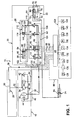
- Fig. 1 shows a numbered with 10 device for hydraulic Actuation of a friction clutch and a mechanical Manual transmission in a motor vehicle.
- the actuator 10 can be roughly divided into three hydraulic sections, namely a pressure supply section, a hydraulic Functional section and a pressure relief section, which are hydraulically interconnected.
- the pressure supply section has a later described in more detail Power unit 12 for generating a hydraulic pressure on.
- To the pressure supply section is the hydraulic Function section over in the illustrated embodiment four control organs 14, 16, 18, 20 connected, which also to be described in more detail.
- the hydraulic functional section on the one hand has a transmitter unit 22 for hydraulic Control one with the friction clutch in known per se Way operable actuating cylinder 24 (conventional clutch slave cylinder or Gottausschreiber), by means of which the Friction clutch is optional off or engageable.
- the hydraulic function section with the manual transmission operable multi-position cylinder system 26, which hydraulically for gear or lane selection in the manual transmission is controllable.
- the pressure relief section finally includes a supply and return tank 28 for the hydraulic fluid the actuator 10. It is essential that at least the control members 14, 16, 18, 20, the encoder unit 22nd and the multi-position cylinder system 26 of the actuator 10 are integrated into or in a functional block 30, such as will be explained in detail below.
- the input side via a suction line 32 to the reservoir 28 connected power unit 12 has a hydraulic pump 34, which may be selected by means of e.g. an electric motor M driven can be to hydraulic fluid through the suction line 32 to promote from the reservoir 28.
- the exit the hydraulic pump 34 is connected by means of a pressure line 36 via a check valve 38 connected to a pressure accumulator 40.
- a pressure relief valve 42 is provided, which prevents the downstream of the hydraulic pump 34 prevailing hydraulic Pressure exceeds a predetermined value by reaching it the predetermined pressure value, the pressure line 36 temporarily connects to the intake manifold 32.
- hydraulic Pressure is also a pressure switch 44 to the pressure line 36 connected.
- the pressure switch 44 is connected via an electrical Signal line 46 is connected to an electronic control unit 48, the et al serves to the electric motor M via an electrical control line 50 to drive.
- the power unit 12 are controlled by the control electronics 48 such that the power unit 12 via the pressure line 36 a variable liquid flow, each with a defined volume flow and defined pressure.
- the power unit 12 is connected via the pressure line 36 to the Function block 30, more precisely via a pressure port 52 of the Functional block 30 to a in the illustrated embodiment connected in the function block 30 formed pressure channel 54.
- the end forming the pressure supply section Pressure channel 54 serves the common supply of the control organs 14, 16, 18 and 20 with hydraulic fluid.
- the tank channel forming the beginning of the pressure relief section 62 serves the common pressure relief of the control organs 14, 16, 18 and 20 to the reservoir 28 out.
- control member 14 which via a Encoder channel 64 in the function block 30 hydraulically with the encoder unit 22 is connected to the hydraulic clutch actuation, it is a proportional valve in 3/2-way design. It is by means of a spring in those shown in Fig. 1 Initial position biased in which it is the encoder channel 64 with the Tank channel 62 connects, and can be actuated electromagnetically to supply the transmitter unit 22 with hydraulic fluid connect the pressure channel 54 with the encoder channel 64, what for it via an electrical control line 66 to the Control electronics 48 is connected.
- the transmitter unit 22 has a master piston 68, the one on his right in Fig. 1 side with the encoder channel 64 communicating transducer pressure chamber 70 and on its in Fig. 1 left side limited a slave pressure chamber 72.
- a compression spring 74 is arranged, which the master piston 68 biased in its rest position shown in Fig. 1. In the Rest position of the master piston 68 is u.a.
- the transmitter unit 22 also has in the region of the slave pressure chamber 72nd a slave terminal 80 for a pressure line 82 through which the known and therefore not described here in detail, with the friction clutch (not shown) operatively connected actuating cylinder 24 are hydraulically acted upon by the encoder unit 22 can.
- the actuating cylinder 24 is finally with a displacement sensor 84 for detecting the disengagement or engagement stroke on the friction clutch equipped, via an electrical signal line 86 to the Control electronics 48 is connected.
- control member 16 which via a connection channel 88 in the function block 30 with a selector cylinder 90 of the multi-position cylinder system 26 hydraulically is connected, it is a proportional valve in 3/2-way design, so that the control member 16 - as well as the control member 14 - no unpressurized center position that could lead to problems when in hydraulic Functional section due to leaks Pressure drops would come.
- the control member 16 is in turn by means of biased a spring into the basic position shown in Figure 1, in which it the connecting channel 88 with the tank channel 62nd connects, and can be electromagnetically actuated to Supply of the selector cylinder 90 with hydraulic fluid Pressure channel 54 to connect to the connecting channel 88.
- an electrical control line 92 connected to the control electronics 48.
- the choice of the respective shift gate in the mechanical transmission (not shown) serving selector cylinder 90 has a selector piston 94, on its in Fig. 1 right side communicating with the connection channel 88 Pressure chamber 96 limited.
- a compression spring 98 is provided which the selector piston 94 biased in its rest position shown in Fig. 1. It can be seen that the selector piston 94 by electrical control the control member 16 by means of the control electronics 48th and the concomitant pressurization of the pressure chamber 96 from the pressure channel 54 via the connecting channel 88 from its Rest position against the force of the compression spring 98 in FIG. 1 can be moved to the left.
- Fig. 1 finally, it can be seen that to the control electronics 48 also external components or groups connected are numbered 124 here in general.
- the engine management 126 which receives signals from an engine speed sensor 128 and receives a sensor 130 for the accelerator pedal position, the Ignition 132, a sensor 134 for the shift lever position, Wheel speed sensors 136, gear indicator 138, warning devices 140 and a sensor 142 for the transmission speed. Since the external components or groups 124 and their interaction with the control electronics 48 on the one hand Experts are well known and on the other hand related Explanations for understanding the present invention do not appear necessary, should be further explanations refrain from this at this point.
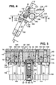
- the functional block 30 is attached to it Tax organs 14, 16, 18 and 20 and also attached thereto encoder unit 22 shown in more detail, wherein the Fig. 4 shows the function block 30 in the position that the function block 30 in the housing of the gearbox (not shown) assembled state assumes.
- FIGS. 2 to 4 in particular, it preferably has an extruded profile of a light metal such as an aluminum alloy formed functional block 30 a in the longitudinal direction the functional block 30 extending planar mounting surface 144 and a flat flange surface 146, which also in the longitudinal direction of the functional block 30 extends and with the construction area 144 includes an angle of about 115 °.
- the function block 30 ends in each case with a plane End face 148, 150, perpendicular to the mounting surface 144 and extend to the flange 146.
- the functional block 30 At the front in Fig. 2 is the functional block 30 further on its in Fig. 2 provided on the left side with a recess that there is a second front, with respect to the end face 148 in Fig. 2 after Rear offset flat end surface 152 is formed, the parallel to the end surfaces 148, 150 extends.
- control members 14, 16, 18th and 20 and the transmitter unit 22 each in cartridge construction executed and flanged to the mounting surface 144.
- the controls 14, 16, 18 and 20 and the encoder unit 22 each have a substantially cup-shaped, preferably metallic housing 154, 156, 158, 160 and 162, respectively. While in the housings 154, 156, 158 and 160 of the control members 14, 16, 18th or 20 each a per se known electromagnetic drive and a valve spring of the respective control member 14, 16, 18th or 20 are included - as the Fig.
- FIG. 5 shows - in the Housing 162 of the encoder unit 22, a cylinder bore 163 is formed, which the sliding receiving the opposite the cylinder bore 163 suitably sealed master piston 68 is used and in the remote from the functional block 30 end of the housing 162 of the slave terminal 80 opens.
- each one is the housings 154, 156, 158, 160 and 162 - as also shown in FIG. 5 can be seen - at its the functional block 30 facing End provided with an annular flange 164, 166, 168, 170 and 172, with its the functional block 30 facing end side abuts on the mounting surface 144.
- the annular flanges 164, 166, 168, 170 and 172 of the housings 154, 156, 158, 160 and 162, respectively are engaged behind by a flange 174, the five openings through which the housings 154, 156, 158, 160 or 162 with very slight radial play each through extend.
- the flange plate 174 itself is a plurality of, in the illustrated embodiment twelve evenly on Edge of the flange plate 174 distributed screws 176 on the function block 30 screwed to the control members 14, 16, 18 and 20 and the encoder unit 22 to be attached to the function block 30.
- controllers 14, 16, 18 and 20 are and the encoder unit 22 at the mounting surface 144 of the functional block 30 flanged state in a row one behind the other arranged, wherein the encoder unit 22 centrally between the Control members 14, 16, 18 and 20 is located, and the control member 14th for the transmitter unit 22 is arranged adjacent thereto.
- each control member 14, 16, 18 and 20 a designed as a stepped blind bore connecting hole 178, 180, 182 and 184 for receiving a respective associated valve spool 186, 188, 190 and 192 assigned to which the electromagnetic drive and the valve spring of the respective control member 14, 16, 18 and 20 attack and in Fig. 6 for simplicity the illustration are not shown.
- the connection holes 178, 180, 182 and 184 are starting from the construction area 144 and introduced perpendicular to this in the function block 30. Center between the connection holes 178, 180, 182 and 184 is a cylindrical, emanating from the mounting surface 144 Recess 194 provided in the function block 30, the - like can be seen in Fig. 5 - the sealed recording of an the annular flange 172 subsequent cylindrical extension 196th of the housing 162 of the encoder unit 22 is used.
- Figs. 2, 4, 5, 6 and 8 are starting from the end face 152 and perpendicular to this both the Pressure channel 54 with the pressure port 52 and the tank channel 62 with the tank port 60 as stepped at the entrance blind holes introduced into the function block 30, so that these channels 54, 62 in the longitudinal direction of the function block 30 parallel to each other and to the mounting surface 144 and the flange surface 146 of the functional block 30 run.
- Both the pressure channel 54 and the tank channel 62 are within the function block 30 with each of the parallel Connection bores 178, 180, 182 and 184 for the control organs 14, 16, 18 and 20 in conjunction. More specifically, according to Figs.
- Fig. 8 it can be seen how the control member 14 hydraulically is connected to the encoder unit 22:
- Donor channel 64 is starting from the bottom of the recess 194 a Sack bore 198 introduced into the function block 30, while a transverse to the blind bore 198 extending, the connection bore 178 for the control member 14 on the edge cutting further blind hole 200 starting from a side surface of the function block 30 is inserted into this, that the blind holes 198, 200 end in one another.
- 202 in Figs. 2 and 8 indicated that the blind bore 200 at her in the side surface of the function block 30 opening end with a suitable Closure is provided.
- the multi-position cylinder system is also 26 integrated in the function block 30.
- Figs. 6 and 8 show - starting from each of an end face 148, 150 of the functional block 30 and perpendicular to the respective end face 148, 150 cylinder bores 204, 206 as lying on a common axis, in the longitudinal direction of the function block 30 extending blind holes in introduced the functional block 30.
- cylinder bore 204 is the opposite of the cylinder bore 204 in a suitable manner sealed selector piston 94 of the selector cylinder 90 longitudinally displaceable added.
- the selector piston 94 limited to its in Fig. 6 lower side in the cylinder bore 204, the pressure chamber 96 of the Wählzylinders 90.
- the switching piston 114th the shift cylinder 112 received longitudinally displaceable is the also suitably sealed relative to the cylinder bore 206 is.
- the switching piston 114 limited to its in Fig. 6 upper side of the pressure chamber 116 of the shift cylinder 112 in the Cylinder bore 206, while on his in Fig. 6 lower Side limits the pressure chamber 118 of the switching cylinder 112.
- To outside is also the cylinder bore 206 by means of a plug 212 closed, which is inserted into the cylinder bore 206 and secured in this with the aid of a snap ring 214 is.
- connection channel 108 is formed by a transverse bore, starting from the in Fig. 8 front side surface of the functional block 30 a the Connecting channel 88 forming transverse bore in the function block 30 introduced, the first the connection hole 180 for the control member 16 at the edge cuts - as well as in Fig. 6 is recognized - before they in the pressure chamber 96 of the selector cylinder 90th opens - as well as Fig. 6 shows. That is in the side surface the function block 30 opening end of the connection channel 88 is shown in FIGS. 2 and 8 by means of a suitable closure 216 closed. Also, the connection channel 108 is formed by a transverse bore, starting from the in Fig.
- connection channel 110 is by a starting from the front in Fig. 8 side surface formed in the functional block 30 transverse bore, the, after they the connection bore 184 for the control member 20 cut on the edge, in the pressure chamber 118 of the shift cylinder 112 opens (see again Fig. 6).
- connection channel 108 as well as the connecting channel 110 to Mehr einszylindersystem 26 are shown in FIGS. 2 and 8 at their in the side surface of the functional block 30 opening ends each provided with a hydraulically sealed closure 218, 220.
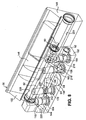
- FIGS. 3, 6 and 7 show further details, such as the multi-position cylinder system located in the functional block 30 26 with the manual transmission, from that in Fig. 7 only a switching shaft 222 is indicated by dash-dotted lines, is in active connection.
- the functional block 30 is starting from its flange surface 146, by means of which it on the gear housing (not shown) can be flanged, with recesses 224, 226 for receiving mechanical links provided over which the Mehr josszylindersystem 26 with the Switching shaft 222 of the gearbox is operatively connected.
- an angle lever 228 assigned to the selector cylinder 90 shown received in the recess 224 of the functional block 30 is.
- the bell crank 228 has two legs 230, 232, which are interconnected by means of a bearing sleeve 234.
- the bearing sleeve 234 is mounted on a bearing pin 236, the is attached to the function block 30 as shown in FIGS. 2 and 4, so that the angle lever 228 are pivoted about the bearing pin 236 can.
- the leg 230 passes through the angle lever 228 an opening 238 between the recess 224 and the cylinder bore 204 in the function block 30, to - as in the Fig. 6 and 7 can be seen - in a radial groove 240 on the selector piston 94 intervene.
- FIGS. 3 and 6 is also between the recess 226 and the cylinder bore 206 of the shift cylinder 112 an opening 244 provided in the function block 30.
- an opening 244 provided in the function block 30.
- Mit vide 246 with its in Fig. 7 left end in a radial groove 248 engages formed on the control piston 114 is, while the driver 246 with his right in Fig. 7 End on not shown here manner on the switching shaft 222 attacks.
- the switching shaft 222 via the driver 246 in the longitudinal direction of the switching shaft 222 with shifted becomes. This is in the lower part of Fig. 7 by the arrows on Switching piston 114 or indicated on the switching shaft 222.
- FIGS. 2 to 6 To the function block 30 shown in FIGS. 2 to 6 is It should also be noted that he also has a plurality of, in the illustrated Embodiment ten stepped mounting holes 250, which extends through the functional block 30 to extend to the flange 146, but without to cut the hydraulic bores.
- the mounting holes 250 serve to receive screws (not shown), over which the functional block 30 with its flange 146th against the transmission housing (not shown) tightened can.
- FIGS. 2 to 4 that associated with the selector cylinder 90 and the shift cylinder 112 Displacement sensors 100 and 120 combined to form a double sensor S. are provided with an output signal terminal A. is attached to the outside of the function block 30 and by means of which the axial position of each of the selector piston 94 and the switching piston 114 mounted ring magnet R (see Fig. 6) in the function block 30 can be detected.
- the functional block 30 with hydraulic fluid in a predetermined Amount and supplied with predetermined pressure is used by the control electronics 48 first the control member 14 is driven, which then the pressure channel 54 with the encoder channel 64th connects, whereby the transmitter pressure chamber 70 in the encoder unit 22nd is pressurized and it subsequently becomes a shift the master piston 68 comes.
- the master piston 68 shifts now hydraulic fluid from the slave pressure chamber 72 via the Slave connection 80 and the pressure line 82 in the actuating cylinder 24, through which then the friction clutch is disengaged.
- the control electronics 48 first controls the control member 16, which in the sequence the pressure channel 54 with the Connecting channel 88 connects, so that the pressure chamber 96 of the Wählzylinders 90 is pressurized to the desired extent.
- the selector piston 94 is displaced in the cylinder bore 204, what to choose the desired shift gate twisting the shift shaft 222 via the angle lever 228 on the already described Way causes.
- Switching piston 114 It thus creates a pressure difference on Switching piston 114, which causes the switching piston 114 in the desired direction as well as with the desired force and Speed in the cylinder bore 206 is moved.
- the switching piston 114 takes on the already described Way the shift shaft 222 in the longitudinal direction with, and the respective gear is engaged after synchronization.
- the friction clutch can be engaged again, what a Control of the control member 14 is carried out such that this Encoder unit 22, more precisely, the encoder pressure chamber 70 via the Encoder channel 64 to the tank channel 62 toward desired pressure relieved.
- the actuating cylinder 24 by the spring force reset the engaging friction clutch, which from the Actuator 24 displaced volume of hydraulic fluid again via the pressure line 82 into the slave pressure chamber 72 of the Encoder unit 22 is pushed back.
- this device has a pressure supply section with a power unit for generating a hydraulic Second, one to the pressure supply section above Control elements connected hydraulic functional section, on the one hand a transmitter unit for hydraulic control a functionally operable with the friction clutch, the latter optionally off and on-coming actuator cylinder and on the other hand with a the gearbox operatively engageable, to the aisle or lane selection having hydraulically controllable multi-position cylinder system, and third, a pressure relief section with a reservoir for the hydraulic fluid.
- the invention at least the controls, the transmitter unit and the multi-position cylinder system the device on or in the function block integrated. The result is a hydraulic function block created for the clutch and gearbox operation, by the undesired pressure and path losses to the driven Slave cylinders are largely avoided.
Landscapes
- Engineering & Computer Science (AREA)
- General Engineering & Computer Science (AREA)
- Mechanical Engineering (AREA)
- Physics & Mathematics (AREA)
- Fluid Mechanics (AREA)
- Hydraulic Clutches, Magnetic Clutches, Fluid Clutches, And Fluid Joints (AREA)
Abstract
Description
- Fig. 1
- ein Blockschaltbild einer Vorrichtung zur Betätigung einer Reibkupplung (nicht dargestellt) und eines mechanischen Schaltgetriebes (nicht dargestellt) in einem Kraftfahrzeug - nachfolgend kurz "Betätigungsvorrichtung" genannt - bei der ein erfindungsgemäßer hydraulischer Funktionsblock zum Einsatz kommt,
- Fig. 2
- eine perspektivische Darstellung eines erfindungsgemäßen hydraulischen Funktionsblocks von schräg vorne im nicht am Getriebegehäuse angeflanschten Zustand, an dem Steuerorgane für einen hydraulischen Funktionsabschnitt der Betätigungsvorrichtung und eine zur hydraulischen Kupplungsbetätigung vorgesehene Gebereinheit des hydraulischen Funktionsabschnitts in Patronenbauweise angeflanscht sind,
- Fig. 3
- eine perspektivische Darstellung des hydraulischen Funktionsblocks gemäß Fig. 2 von schräg hinten mit Blick auf eine Flanschfläche, über die der Funktionsblock am Getriebegehäuse (nicht dargestellt) anflanschbar ist,
- Fig. 4
- eine Seitenansicht des hydraulischen Funktionsblocks gemäß Fig. 2,
- Fig. 5
- eine Schnittansicht des hydraulischen Funktionsblocks gemäß Fig. 2 entsprechend der Schnittverlaufslinie V-V in Fig. 4, wobei Magnetantriebe der Steuerorgane für den hydraulischen Funktionsabschnitt der Betätigungsvorrichtung zur Vereinfachung der Darstellung nicht geschnitten dargestellt sind,
- Fig. 6
- eine Schnittansicht des hydraulischen Funktionsblocks gemäß Fig. 2 entsprechend der Schnittverlaufslinie VI-VI in Fig. 4, welche die Kolben eines mit dem Schaltgetriebe wirkverbindbaren, im Funktionsblock integrierten Mehrstellungszylindersystems in ihrer Ruhestellung zeigt,
- Fig. 7
- eine hinsichtlich des Schnittverlaufs der Darstellung gemäß Fig. 6 entsprechende, schematische Schnittansicht des hydraulischen Funktionsblocks gemäß Fig. 2 in einem gegenüber Fig. 6 kleineren Maßstab, die veranschaulicht, wie das im Funktionsblock integrierte Mehrstellungszylindersystem mit einer Schaltwelle des Schaltgetriebes in Wirkverbindung steht, und
- Fig. 8
- eine perspektivische Transparenzdarstellung des hydraulischen Funktionsblocks gemäß Fig. 2 ohne angeflanschte Anbauteile, welche in der Art eines Drahtmodells die Anordnung und den Verlauf der Hohlräume in dem hydraulischen Funktionsblock veranschaulicht.
- 10
- Betätigungsvorrichtung
- 12
- Leistungseinheit
- 14
- Steuerorgan
- 16
- Steuerorgan
- 18
- Steuerorgan
- 20
- Steuerorgan
- 22
- Gebereinheit
- 24
- Stellzylinder
- 26
- Mehrstellungszylindersystem
- 28
- Vorratsbehälter
- 30
- Funktionsblock
- 32
- Ansaugleitung
- 34
- Hydraulikpumpe
- 36
- Druckleitung
- 38
- Rückschlagventil
- 40
- Druckspeicher
- 42
- Druckbegrenzungsventil
- 44
- Druckwächter
- 46
- Signalleitung
- 48
- Steuerelektronik
- 50
- Steuerleitung
- 52
- Druckanschluß
- 54
- Druckkanal
- 56
- Filter
- 58
- Tankleitung
- 60
- Tankanschluß
- 62
- Tankkanal
- 64
- Geberkanal
- 66
- Steuerleitung
- 68
- Geberkolben
- 70
- Geberdruckraum
- 72
- Nehmerdruckraum
- 74
- Druckfeder
- 76
- Drossel
- 78
- Verbindungsabschnitt
- 80
- Nehmeranschluß
- 82
- Druckleitung
- 84
- Wegsensor
- 86
- Signalleitung
- 88
- Verbindungskanal
- 90
- Wählzylinder
- 92
- Steuerleitung
- 94
- Wählkolben
- 96
- Druckraum
- 98
- Druckfeder
- 100
- Wegsensor
- 102
- Signalleitung
- 104
- Steuerleitung
- 106
- Steuerleitung
- 108
- Verbindungskanal
- 110
- Verbindungskanal
- 112
- Schaltzylinder
- 114
- Schaltkolben
- 116
- Druckraum
- 118
- Druckraum
- 120
- Wegsensor
- 122
- Signalleitung
- 124
- externe Bauelemente bzw. -gruppen
- 126
- Motormanagement
- 128
- Sensor für die Motordrehzahl
- 130
- Sensor für die Fahrpedalstellung
- 132
- Zündung
- 134
- Sensor für die Schalthebelstellung
- 136
- Sensoren für die Raddrehzahlen
- 138
- Ganganzeige
- 140
- Warnsignaleinrichtungen
- 142
- Sensor für die Getriebedrehzahl
- 144
- Aufbaufläche
- 146
- Flanschfläche
- 148
- Stirnfläche
- 150
- Stirnfläche
- 152
- Stirnfläche
- 154
- Gehäuse
- 156
- Gehäuse
- 158
- Gehäuse
- 160
- Gehäuse
- 162
- Gehäuse
- 163
- Zylinderbohrung
- 164
- Ringflansch
- 166
- Ringflansch
- 168
- Ringflansch
- 170
- Ringflansch
- 172
- Ringflansch
- 174
- Flanschplatte
- 176
- Schraube
- 178
- Anschlußbohrung
- 180
- Anschlußbohrung
- 182
- Anschlußbohrung
- 184
- Anschlußbohrung
- 186
- Ventilschieber
- 188
- Ventilschieber
- 190
- Ventilschieber
- 192
- Ventilschieber
- 194
- Aussparung
- 196
- Fortsatz
- 198
- Sackbohrung
- 200
- Sackbohrung
- 202
- Verschluß
- 204
- Zylinderbohrung
- 206
- Zylinderbohrung
- 208
- Stopfen
- 210
- Sprengring
- 212
- Stopfen
- 214
- Sprengring
- 216
- Verschluß
- 218
- Verschluß
- 220
- Verschluß
- 222
- Schaltwelle
- 224
- Ausnehmung
- 226
- Ausnehmung
- 228
- Winkelhebel
- 230
- Schenkel
- 232
- Schenkel
- 234
- Lagerhülse
- 236
- Lagerbolzen
- 238
- Durchbruch
- 240
- Radialnut
- 242
- Kugelzapfen
- 244
- Durchbruch
- 246
- Mitnehmer
- 248
- Radialnut
- 250
- Befestigungsbohrung
- A
- Ausgangssignalanschluß
- M
- Elektromotor
- R
- Ringmagnet
- S
- Doppelsensor
Claims (17)
- Hydraulischer Funktionsblock (30) für eine Vorrichtung (10) zur Betätigung einer Reibkupplung und eines mechanischen Schaltgetriebes insbesondere in einem Kraftfahrzeug, wobei die Vorrichtung (10) umfaßt:dadurch gekennzeichnet, daß zumindest die Steuerorgane (14, 16, 18, 20), die Gebereinheit (22) und das Mehrstellungszylindersystem (26) der Vorrichtung (10) an bzw. in dem Funktionsblock (30) integriert sind.(a) einen Druckversorgungsabschnitt mit einer Leistungseinheit (12) zur Erzeugung eines hydraulischen Drucks,(b) einen an den Druckversorgungsabschnitt über Steuerorgane (14, 16, 18, 20) angeschlossenen hydraulischen Funktionsabschnitt mit einer Gebereinheit (22) zur hydraulischen Ansteuerung eines mit der Reibkupplung wirkverbindbaren Stellzylinders (24), mittels dessen die Reibkupplung wahlweise aus- bzw. einrückbar ist, und einem mit dem Schaltgetriebe wirkverbindbaren Mehrstellungszylindersystem (26), welches zur Gang- bzw. Gassenwahl hydraulisch ansteuerbar ist, sowie(c) einen Druckentlastungsabschnitt mit einem Vorratsbehälter (28) für die Hydraulikflüssigkeit,
- Hydraulischer Funktionsblock (30) nach Anspruch 1, dadurch gekennzeichnet, daß die Steuerorgane (14, 16, 18, 20) und die Gebereinheit (22) in Patronenbauweise ausgeführt sind und der Funktionsblock (30) eine vorzugsweise ebene Aufbaufläche (144) hat, an der die Steuerorgane (14, 16, 18, 20) und die Gebereinheit (22) anflanschbar sind.
- Hydraulischer Funktionsblock (30) nach Anspruch 2, dadurch gekennzeichnet, daß die Steuerorgane (14, 16, 18, 20) und die Gebereinheit (22) im an der Aufbaufläche (144) des Funktionsblocks (30) angeflanschten Zustand in einer Reihe hintereinander angeordnet sind.
- Hydraulischer Funktionsblock (30) nach Anspruch 3, dadurch gekennzeichnet, daß die Gebereinheit (22) mittig zwischen den Steuerorganen (14, 16, 18, 20) angeordnet ist und das Steuerorgan (14) für die Gebereinheit (22) der Gebereinheit (22) benachbart liegt.
- Hydraulischer Funktionsblock (30) nach einem der Ansprüche 2 bis 4, dadurch gekennzeichnet, daß jedem Steuerorgan (14, 16, 18, 20) eine Anschlußbohrung (178, 180, 182, 184) zur Aufnahme eines jeweils zugehörigen Ventilschiebers (186, 188, 190, 192) zugeordnet ist, die ausgehend von der Aufbaufläche (144) in den Funktionsblock (30) eingebracht ist.
- Hydraulischer Funktionsblock (30) nach einem der vorhergehenden Ansprüche, dadurch gekennzeichnet, daß der Druckversorgungsabschnitt einen gemeinsamen Druckkanal (54) für die Steuerorgane (14, 16, 18, 20) aufweist, der im Funktionsblock (30) ausgebildet ist.
- Hydraulischer Funktionsblock (30) nach einem der vorhergehenden Ansprüche, dadurch gekennzeichnet, daß der Druckentlastungsabschnitt einen gemeinsamen Tankkanal (62) für die Steuerorgane (14, 16, 18, 20) aufweist, der im Funktionsblock (30) ausgebildet ist.
- Hydraulischer Funktionsblock (30) nach den Ansprüchen 5 bis 7, dadurch gekennzeichnet, daß jede Anschlußbohrung (178, 180, 182, 184) mit dem Druckkanal (54) und dem Tankkanal (62) innerhalb des Funktionsblocks (30) in Verbindung steht, vorzugsweise sowohl den Druckkanal (54) als auch den Tankkanal (62) schneidet.
- Hydraulischer Funktionsblock (30) nach Anspruch 8, dadurch gekennzeichnet, daß in der Einbaulage des Funktionsblocks (30) der Tankkanal (62) oberhalb des Druckkanals (54) liegt und die Anschlußbohrungen (178, 180, 182, 184) steigend verlaufen.
- Hydraulischer Funktionsblock (30) nach den Ansprüchen 6 und 7 oder Anspruch 8 oder 9, dadurch gekennzeichnet, daß der Druckkanal (54) und der Tankkanal (62) parallel zueinander verlaufen.
- Hydraulischer Funktionsblock (30) nach Anspruch 10, dadurch gekennzeichnet, daß die zur Aufnahme der Ventilschieber (186, 188, 190, 192) der Steuerorgane (14, 16, 18, 20) vorgesehenen Anschlußbohrungen (178, 180, 182, 184) parallel zueinander sowie rechtwinklig bezüglich des Druckkanals (54) und des Tankkanals (62) im Funktionsblock (30) verlaufen.
- Hydraulischer Funktionsblock (30) nach einem der vorhergehenden Ansprüche, dadurch gekennzeichnet, daß das Mehrstellungszylindersystem (26) einen Wählzylinder (90) zur Gassenwahl sowie einen Schaltzylinder (112) zur Gangwahl hat, die (90, 112) jeweils einen Kolben (94, 114) aufweisen, der in einer jeweils zugeordneten Zylinderbohrung (204, 206) verschiebbar aufgenommen ist, wobei die Zylinderbohrungen (204, 206) in dem Funktionsblock (30) ausgebildet sind.
- Hydraulischer Funktionsblock (30) nach Anspruch 12, dadurch gekennzeichnet, daß die Zylinderbohrungen (204, 206) ausgehend von jeweils einer Stirnfläche (148, 150) des Funktionsblocks (30) in den Funktionsblock (30) eingebracht sind und vorzugsweise auf einer gemeinsamen Achse liegen.
- Hydraulischer Funktionsblock (30) nach Anspruch 12 oder 13, dadurch gekennzeichnet, daß die Zylinderbohrungen (204, 206) über Querbohrungen (88, 108, 110) mit den zur Aufnahme der Ventilschieber (188, 190, 192) der Steuerorgane (16, 18, 20) für das Mehrstellungszylindersystem (26) im Funktionsblock (30) vorgesehenen Anschlußbohrungen (180, 182, 184) verbunden sind.
- Hydraulischer Funktionsblock (30) nach einem der vorhergehenden Ansprüche, dadurch gekennzeichnet, daß der Funktionsblock (30) eine vorzugsweise ebene Flanschfläche (146) aufweist, mittels der er an einem Getriebegehäuse anflanschbar ist, wobei der Funktionsblock (30) ausgehend von der Flanschfläche (146) mit Ausnehmungen (224, 226) zur Aufnahme von mechanischen Verbindungsgliedern (228, 246) versehen ist, über die das Mehrstellungszylindersystem (26) mit einer Schaltwelle (222) des Schaltgetriebes wirkverbindbar ist.
- Hydraulischer Funktionsblock (30) nach den Ansprüchen 2, 6, 7, 12 und 15, dadurch gekennzeichnet, daß die Aufbaufläche (144), der Druckkanal (54), der Tankkanal (62), die Zylinderbohrungen (204, 206) und die Flanschfläche (146) in Längsrichtung des Funktionsblocks (30) verlaufen.
- Hydraulischer Funktionsblock (30) nach einem der vorhergehenden Ansprüche, dadurch gekennzeichnet, daß der Funktionsblock (30) aus einem Strangpreßprofil aus einem Leichtmetall wie einer Aluminiumlegierung ausgebildet ist.
Applications Claiming Priority (2)
| Application Number | Priority Date | Filing Date | Title |
|---|---|---|---|
| DE10360611A DE10360611A1 (de) | 2003-12-19 | 2003-12-19 | Hydraulischer Funktionsblock |
| DE10360611 | 2003-12-19 |
Publications (3)
| Publication Number | Publication Date |
|---|---|
| EP1544492A1 true EP1544492A1 (de) | 2005-06-22 |
| EP1544492B1 EP1544492B1 (de) | 2007-07-18 |
| EP1544492B8 EP1544492B8 (de) | 2007-09-19 |
Family
ID=34485578
Family Applications (1)
| Application Number | Title | Priority Date | Filing Date |
|---|---|---|---|
| EP04029748A Expired - Lifetime EP1544492B8 (de) | 2003-12-19 | 2004-12-16 | Hydraulischer Funktionsblock |
Country Status (2)
| Country | Link |
|---|---|
| EP (1) | EP1544492B8 (de) |
| DE (2) | DE10360611A1 (de) |
Cited By (4)
| Publication number | Priority date | Publication date | Assignee | Title |
|---|---|---|---|---|
| EP1821005A1 (de) * | 2006-02-17 | 2007-08-22 | Magneti Marelli Powertrain S.p.A. | Hydraulischer Servomotor zum Schalten von Gängen |
| DE102007023072A1 (de) | 2007-05-16 | 2008-11-20 | Volkswagen Ag | Hydraulische Steuerungseinrichtung für ein Getriebe |
| CN102110382A (zh) * | 2011-01-17 | 2011-06-29 | 浙江大学 | 液压式围绕z轴无限旋转的模拟器平台 |
| DE102014105899A1 (de) | 2014-04-28 | 2015-10-29 | Getrag Getriebe- Und Zahnradfabrik Hermann Hagenmeyer Gmbh & Cie Kg | Schalt-Aktuatoranordnung und Kraftfahrzeuggetriebe |
Families Citing this family (6)
| Publication number | Priority date | Publication date | Assignee | Title |
|---|---|---|---|---|
| DE102006040136A1 (de) * | 2006-08-26 | 2008-03-06 | Zf Friedrichshafen Ag | Automatisiertes Schaltgetriebe |
| CN102110383B (zh) * | 2011-01-17 | 2012-05-02 | 浙江大学 | 液压式围绕z轴旋转方向免于洗出算法的模拟器平台 |
| DE102011107263A1 (de) | 2011-07-06 | 2013-01-10 | Fte Automotive Gmbh | Hydraulische Betätigungsvorrichtung für die Betätigung eines oder mehrerer Stellglieder in insbesondere einem Kraftfahrzeuggetriebe |
| DE102013000157B3 (de) * | 2013-01-09 | 2014-01-23 | Fte Automotive Gmbh | Hydraulische Betätigungsvorrichtung für die Betätigung wenigstens einer Reibkupplung und wenigstens eines Getriebestellglieds in einem Kraftfahrzeug |
| US9803702B2 (en) | 2012-07-03 | 2017-10-31 | Fte Automotive Gmbh | Hydraulic actuating device for actuation of at least one friction clutch and at least one gear setting element in a motor vehicle |
| DE102018102690C5 (de) | 2018-02-07 | 2024-10-24 | Schaeffler Technologies AG & Co. KG | Hydraulische Aktorik |
Citations (3)
| Publication number | Priority date | Publication date | Assignee | Title |
|---|---|---|---|---|
| DE4309901A1 (de) * | 1992-11-10 | 1994-09-29 | Fichtel & Sachs Ag | Hydraulischer Stellantrieb - inbesondere für eine Kraftfahrzeug-Reibungskupplung |
| DE19944653A1 (de) * | 1999-09-17 | 2001-04-26 | Mannesmann Sachs Ag | Hydraulisches System zum Betätigen einer oder mehrerer hydraulisch zu betätigender Komponenten in einem Fahrzeug sowie Verfahren zum Herstellen und Einbauen eines hydraulischen Systems |
| DE20015782U1 (de) * | 2000-01-10 | 2001-06-07 | Lunke Ventra Automotive GmbH, 58455 Witten | Elektro-hydraulische Steuerung für ein Personenkraftfahrzeug-Getriebe |
Family Cites Families (3)
| Publication number | Priority date | Publication date | Assignee | Title |
|---|---|---|---|---|
| US4625840A (en) * | 1983-08-19 | 1986-12-02 | Diesel Kiki Co., Ltd. | Hydraulic control unit for automotive transmissions |
| GB2309494B (en) * | 1995-09-12 | 2000-04-19 | Luk Getriebe Systeme Gmbh | Motor vehicle with an apparatus for the actuation of the torque transmitting system and of the transmission |
| DE10009505A1 (de) * | 2000-02-29 | 2001-08-30 | Hydraulik Ring Gmbh | Steuereinrichtung für automatisierte Schaltgetriebe von Fahrzeugen, vorzugsweise von Kraftfahrzeugen |
-
2003
- 2003-12-19 DE DE10360611A patent/DE10360611A1/de not_active Withdrawn
-
2004
- 2004-12-16 DE DE502004004348T patent/DE502004004348D1/de not_active Expired - Lifetime
- 2004-12-16 EP EP04029748A patent/EP1544492B8/de not_active Expired - Lifetime
Patent Citations (3)
| Publication number | Priority date | Publication date | Assignee | Title |
|---|---|---|---|---|
| DE4309901A1 (de) * | 1992-11-10 | 1994-09-29 | Fichtel & Sachs Ag | Hydraulischer Stellantrieb - inbesondere für eine Kraftfahrzeug-Reibungskupplung |
| DE19944653A1 (de) * | 1999-09-17 | 2001-04-26 | Mannesmann Sachs Ag | Hydraulisches System zum Betätigen einer oder mehrerer hydraulisch zu betätigender Komponenten in einem Fahrzeug sowie Verfahren zum Herstellen und Einbauen eines hydraulischen Systems |
| DE20015782U1 (de) * | 2000-01-10 | 2001-06-07 | Lunke Ventra Automotive GmbH, 58455 Witten | Elektro-hydraulische Steuerung für ein Personenkraftfahrzeug-Getriebe |
Non-Patent Citations (1)
| Title |
|---|
| FINDEISEN: "Ölhydraulik", 1994, SPRINGER-VERLAG, BERLIN, XP002318388 * |
Cited By (9)
| Publication number | Priority date | Publication date | Assignee | Title |
|---|---|---|---|---|
| EP1821005A1 (de) * | 2006-02-17 | 2007-08-22 | Magneti Marelli Powertrain S.p.A. | Hydraulischer Servomotor zum Schalten von Gängen |
| US7603923B2 (en) | 2006-02-17 | 2009-10-20 | Magneti Marelli Powertrain S.P.A. | Hydraulic servo for a gear change |
| CN101025229B (zh) * | 2006-02-17 | 2012-01-11 | 玛涅蒂玛瑞利动力系公开有限公司 | 用于换档系统的液压伺服机构 |
| DE102007023072A1 (de) | 2007-05-16 | 2008-11-20 | Volkswagen Ag | Hydraulische Steuerungseinrichtung für ein Getriebe |
| CN102110382A (zh) * | 2011-01-17 | 2011-06-29 | 浙江大学 | 液压式围绕z轴无限旋转的模拟器平台 |
| CN102110382B (zh) * | 2011-01-17 | 2012-09-05 | 浙江大学 | 液压式围绕z轴无限旋转的模拟器平台 |
| DE102014105899A1 (de) | 2014-04-28 | 2015-10-29 | Getrag Getriebe- Und Zahnradfabrik Hermann Hagenmeyer Gmbh & Cie Kg | Schalt-Aktuatoranordnung und Kraftfahrzeuggetriebe |
| EP2940349A2 (de) | 2014-04-28 | 2015-11-04 | GETRAG Getriebe- und Zahnradfabrik Hermann Hagenmeyer GmbH & Cie KG | Schalt-Akutatoranordnung und Kraftfahrzeuggetriebe |
| EP2940349A3 (de) * | 2014-04-28 | 2015-12-30 | GETRAG Getriebe- und Zahnradfabrik Hermann Hagenmeyer GmbH & Cie KG | Schalt-Akutatoranordnung und Kraftfahrzeuggetriebe |
Also Published As
| Publication number | Publication date |
|---|---|
| EP1544492B8 (de) | 2007-09-19 |
| DE10360611A1 (de) | 2005-07-21 |
| EP1544492B1 (de) | 2007-07-18 |
| DE502004004348D1 (de) | 2007-08-30 |
Similar Documents
| Publication | Publication Date | Title |
|---|---|---|
| DE102013000157B3 (de) | Hydraulische Betätigungsvorrichtung für die Betätigung wenigstens einer Reibkupplung und wenigstens eines Getriebestellglieds in einem Kraftfahrzeug | |
| DE3928048C2 (de) | ||
| EP1446590B2 (de) | Antriebsstrang für ein kraftfahrzeug | |
| DE102018112670A1 (de) | Hydraulische Aktorik eines seriellen Hybridgetriebes mit Parksperrenfunktion | |
| DE102007044431A1 (de) | Elektrohydraulische Steuerungsvorrichtung | |
| DE2208842C2 (de) | Antrieb einer Lenkeinrichtung und mehrerer Zubehörgeräte für Fahrzeuge durch ein hydrostatisches Getriebe | |
| DE102011105648A1 (de) | Hydraulische Betätigungsvorrichtung für die Betätigung von Kupplungen in insbesondere einem Mehrkupplungsgetriebe für Kraftfahrzeuge | |
| DE2901051A1 (de) | Hydraulische regeleinrichtung fuer die schaltelemente von lastschaltgetrieben | |
| DE102007047124A1 (de) | Hydroaggregat für eine schlupfregelbare hydraulische Fahrzeugbremsanlage | |
| DE102012200202A1 (de) | Hydraulische Schaltvorrichtung für ein Automatikgetriebe | |
| DE102016118423A1 (de) | Elektrohydraulisches System für die Betätigung von Kupplung(en) und Gangsteller(n) von Schaltgetrieben | |
| EP2940349B1 (de) | Kraftfahrzeuggetriebe | |
| DE60028668T2 (de) | Mehrganggetriebe mit verzögerungsfrei angesteuerten elektrohydraulischen Ventilen | |
| EP1544492B1 (de) | Hydraulischer Funktionsblock | |
| EP1903238B1 (de) | Hydraulisches System | |
| EP2191158B1 (de) | Ansteuerung einer kupplung | |
| EP1048879B1 (de) | Druckmittelversorgung eines CVT-Getriebes | |
| DE69707959T2 (de) | Elektrohydraulische Einrichtung zum Schalten eines servobetätigten Schaltgetriebes | |
| DE102006003517A1 (de) | Hydraulische Steuereinrichtung und Verfahren zur Ansteuerung zweier Aktuatoren | |
| EP3477159A1 (de) | Hydrauliksystem für ein kraftfahrzeuggetriebe | |
| DE19918788A1 (de) | Hydraulisches Betätigungssystem | |
| DE102012017292B4 (de) | Fluidversorgungseinrichtung und Aktuatoranordnung | |
| EP0984185A2 (de) | Hydraulische Stellvorrichtung zur Betätigung einer Kupplung, insbesondere für Kraftfahrzeuge | |
| DE102005041419B4 (de) | Hydraulisches System, insbesondere für Kraftfahrzeuge | |
| DE3710080C1 (de) | Selbsttaetige Schaltvorrichtung eines Planetenraeder-Gangwechselgetriebes mit Mitteln zum Sperren des Einrueckens einer Rueckwaerts-Kupplung und/oder -Bremse |
Legal Events
| Date | Code | Title | Description |
|---|---|---|---|
| PUAI | Public reference made under article 153(3) epc to a published international application that has entered the european phase |
Free format text: ORIGINAL CODE: 0009012 |
|
| AK | Designated contracting states |
Kind code of ref document: A1 Designated state(s): AT BE BG CH CY CZ DE DK EE ES FI FR GB GR HU IE IS IT LI LT LU MC NL PL PT RO SE SI SK TR |
|
| AX | Request for extension of the european patent |
Extension state: AL BA HR LV MK YU |
|
| RAP1 | Party data changed (applicant data changed or rights of an application transferred) |
Owner name: FTE AUTOMOTIVE GMBH Owner name: GETRAG INNOVATIONSCENTER |
|
| 17P | Request for examination filed |
Effective date: 20051214 |
|
| AKX | Designation fees paid |
Designated state(s): DE |
|
| GRAP | Despatch of communication of intention to grant a patent |
Free format text: ORIGINAL CODE: EPIDOSNIGR1 |
|
| GRAS | Grant fee paid |
Free format text: ORIGINAL CODE: EPIDOSNIGR3 |
|
| GRAA | (expected) grant |
Free format text: ORIGINAL CODE: 0009210 |
|
| RIN1 | Information on inventor provided before grant (corrected) |
Inventor name: PETRZIK, GUNTHER, DIPL.-ING. Inventor name: HEUBNER, WILHELM, DIPL.-ING. (FH) Inventor name: SCHAEFER, ANDREAS, DIPL.-ING. Inventor name: RUEHLE, GUENTER, DIPL.-ING. Inventor name: KAISER, JOCHEN, DIPL.-ING. (FH) Inventor name: REUL, ALEXANDER, DIPL.-ING. (FH) Inventor name: SEUFERT, MARTIN, DIPL.-ING. Inventor name: HARST, RICHARD, DIPL.-ING. Inventor name: STOESSEL, ROLAND, DIPL.-ING. (FH) |
|
| AK | Designated contracting states |
Kind code of ref document: B1 Designated state(s): DE |
|
| RAP2 | Party data changed (patent owner data changed or rights of a patent transferred) |
Owner name: GETRAG GETRIEBE- UND ZAHNRADFABRIK HERMANN HAGENME Owner name: FTE AUTOMOTIVE GMBH |
|
| REF | Corresponds to: |
Ref document number: 502004004348 Country of ref document: DE Date of ref document: 20070830 Kind code of ref document: P |
|
| PLBE | No opposition filed within time limit |
Free format text: ORIGINAL CODE: 0009261 |
|
| STAA | Information on the status of an ep patent application or granted ep patent |
Free format text: STATUS: NO OPPOSITION FILED WITHIN TIME LIMIT |
|
| 26N | No opposition filed |
Effective date: 20080421 |
|
| PGFP | Annual fee paid to national office [announced via postgrant information from national office to epo] |
Ref country code: DE Payment date: 20091214 Year of fee payment: 6 |
|
| REG | Reference to a national code |
Ref country code: DE Ref legal event code: R119 Ref document number: 502004004348 Country of ref document: DE Effective date: 20110701 |
|
| PG25 | Lapsed in a contracting state [announced via postgrant information from national office to epo] |
Ref country code: DE Free format text: LAPSE BECAUSE OF NON-PAYMENT OF DUE FEES Effective date: 20110701 |