EP1544582B1 - Electromagnetic flow meter insert - Google Patents
Electromagnetic flow meter insert Download PDFInfo
- Publication number
- EP1544582B1 EP1544582B1 EP04257976.3A EP04257976A EP1544582B1 EP 1544582 B1 EP1544582 B1 EP 1544582B1 EP 04257976 A EP04257976 A EP 04257976A EP 1544582 B1 EP1544582 B1 EP 1544582B1
- Authority
- EP
- European Patent Office
- Prior art keywords
- insert
- flow
- cross
- section
- flow conduit
- Prior art date
- Legal status (The legal status is an assumption and is not a legal conclusion. Google has not performed a legal analysis and makes no representation as to the accuracy of the status listed.)
- Expired - Lifetime
Links
Images


Classifications
-
- G—PHYSICS
- G01—MEASURING; TESTING
- G01F—MEASURING VOLUME, VOLUME FLOW, MASS FLOW OR LIQUID LEVEL; METERING BY VOLUME
- G01F1/00—Measuring the volume flow or mass flow of fluid or fluent solid material wherein the fluid passes through a meter in a continuous flow
- G01F1/56—Measuring the volume flow or mass flow of fluid or fluent solid material wherein the fluid passes through a meter in a continuous flow by using electric or magnetic effects
- G01F1/58—Measuring the volume flow or mass flow of fluid or fluent solid material wherein the fluid passes through a meter in a continuous flow by using electric or magnetic effects by electromagnetic flowmeters
- G01F1/588—Measuring the volume flow or mass flow of fluid or fluent solid material wherein the fluid passes through a meter in a continuous flow by using electric or magnetic effects by electromagnetic flowmeters combined constructions of electrodes, coils or magnetic circuits, accessories therefor
Definitions
- the present invention relates to the field of electromagnetic flow meters, in particular, to the field of insert to define a fluid flow path within an electromagnetic flow meter.
- Electromagnetic flow meters may be used to determine the rate of flow of fluid in a conduit.
- the conduit itself may be used to define the fluid path within the flow meter or an insert, placed within the conduit, may define the fluid path within the flow measurement zone.
- Prior art flow meters, or flow meter inserts generally have a substantially circular cross-section, which may be designed to match the cross-section of the fluid conduit.
- Circular cross-section inserts may be manufactured easily and may provide an effective way to contain the fluid, which may be under pressure.
- the walls of the circular fluid conduit may further be used to support the flow meter insert and, since it is not required to be self-supporting, the flow meter insert may be manufactured economically as a lightweight insert.
- WO 00/47954 A1 discloses such a flow meter insert having a measuring section with a circular cross-section that substantially matches that of the conduit in which it is intended to be inserted.
- GB 2 328 021 A discloses a flow meter insert having a measuring section with a circular cross-section.
- a disadvantage of such flow meters or flow meter inserts is that, due to their generally circular cross-sections, approximations must be made in determining the flow rate of the fluid, they require typically 5-10 diameters of upstream pipe work to ensure an accurate measurement or they are susceptible to the pipe work conditions in surrounding the installation.
- Flow meters or flow meter inserts with substantially square or rectangular cross-sections have been designed for specialist purposes for which a measurement with immunity to flow conditions is required. Such flow meters may provide improved performance when compared to the standard circular cross-section flow meters, but they tend to be bulky to provide the strength required to form a flow conduit and hence are not suitable as general-purpose flow meters.
- GB 2 081 449 A , US 6 237 424 B1 , JP 58 085118 A and JP 4 295722 A all disclose such flow meter inserts.
- the present invention is an elongate moulded insert as defined in Claim 1 of the appended claims. Also provided is a method of manufacturing an elongate insert by moulding, as defined in Claim 8, an electromagnetic flow meter as defined in Claim 11, and a method of manufacturing an electromagnetic flow meter as defined in Claim 12.
- a first aspect provides an insert for an electromagnetic flow meter arranged to be positioned within a flow conduit having a flow conduit cross-section to define a flow path for fluid, wherein the insert comprises an inlet, a measuring section with a measuring cross-section different to the flow conduit cross-section and having at least two substantially parallel sides over at least part of its length and an outlet.
- Using flow meter inserts with at least two substantially parallel sides may also advantageously improve the accuracy of the flow meter readings since such flow meters may be closer to a theoretically ideal flow meter, that is a flow meter with a uniform weight function. This may allow accurate measurements to be obtained even in low hydraulic performance cases. Having at least two substantially parallel sides may also increase the available space for the electrodes and decrease the pressure drops. In addition, the hydraulic performance of the meter may be improved so that the meter may be less sensitive to how it is installed and may provide a higher performance in a non-optimal installation. Also, for a given geometry, the magnetic field may be increased by using an insert with at least two substantially parallel sides. This may allow the coil of the flow meter to be used more efficiently so that a more economical coil may be used and/or less power may be used to drive the coils.
- the insert further comprises a transition section between at least one of the inlet and the outlet and the measuring section wherein the cross-sectional shape of the insert transforms smoothly from the shape of the inlet and/or the outlet to the shape of the measuring section in the transition section.
- the inlet and/or outlet sections comprise a substantially circular cross-section.
- the inlet and/or outlet sections have a cross-sectional shape corresponding to that of a circular conduit.
- the cross-sectional area of the measuring section may cover at least 70% of the cross-sectional area of the flow conduit.
- the cross-sectional area of the measuring section may cover at least 80% of the cross-sectional area of the flow conduit.
- the cross-sectional area of the measuring section may cover less than around 50% of the cross-sectional area of the flow conduit.
- the insert is manufactured by injection moulding, transfer moulding or rotational moulding. Moulding the flow meter insert, from a material such as a plastics or rubber material may allow non-circular flow meter inserts to be provided that are lightweight and economical but that are strong and robust enough to maintain their integrity under fluid pressure.
- the insert may be manufactured substantially from a thermoplastic material; for example, the insert may be manufactured from a glass-loaded plastics material.
- the insert may be manufactured from ABS (acrylonitrile butadiene styrene).
- the insert may be manufactured from another similar material, such as another polymer material, another plastics material or natural or synthetic rubber, such as a soft rubber material or a hard rubber material.
- the insert may be manufactured from a fluorocarbon material such as PTFE (Teflon (RTM)) or ETFE or the insert may be manufactured from PVDF.
- the insert may also be manufactured as a flexible rubber insert.
- the insert may be manufactured substantially from a thermoset material.
- the insert may be manufactured substantially from a reinforced thermoset material.
- the insert may be manufactured substantially from a reinforced thermoplastics material; for example, the insert may be manufactured from a fibreglass material.
- the insert may be bonded to backpotting, which may be provided to give the insert the strength and rigidity required under fluid pressure.
- the method of manufacture of the insert is preferably selected based on the material used for the insert and the most suitable method for the particular material selected, which may be a prior art method, may be used.
- the cross-sectional size and/or shape of the insert may be arranged so that a substantially uniform magnetic field may be applied over substantially the whole cross-sectional area of the measuring section insert.
- a substantially uniform magnetic field may be applied over substantially the whole cross-sectional area of the measuring section insert.
- this may advantageously allow a more accurate measurement of the flow rate to be determined. In some embodiments, this may be achieved, for example by infilling the corners of a substantially square insert.
- the insert may be formed in more than one piece.
- the flow meter in which the insert may be deployed may be a wetted-type or a capacitive-type flow meter.
- the electrodes of the flow meter may be provided integrally with the insert or may be provided as a separate component, for example they may be coupled to the insert.
- the electrodes may comprise metallic or conductive plastics electrodes.
- a variety of electrode configurations may be used in conjunction with the insert and the electrode configuration used may be determined, at least in part, by the cross-section of the insert.
- the magnetic field generating means may be provided integrally with or may be coupled to the insert.
- the magnetic field generating means may comprise a magnetic circuit.
- the magnetic field generating means or magnetic circuit may be provided internally or externally of the insert.
- an electrostatic screen may be provided as part of or in addition to the insert.
- the insert is back-potted on insertion into a flow conduit.
- Back-potting may allow the insert to be supported and stabilised within the conduit and hence may increase the reliability of the flow measurements.
- a further aspect provides a method of manufacturing an insert for an electromagnetic flow meter comprising forming an insert by moulding wherein the insert is formed such that the insert has a conduit therethrough and comprises an inlet, a measuring section with a cross-section having at least two substantially parallel sides over at least part of its length and an outlet.
- Forming the insert using the methods described herein may allow a robust but lightweight insert to be formed.
- the insert is formed from a shape-memory material.
- the insert is formed substantially from a thermoplastic material; for example, the insert may be manufactured from a glass-loaded plastics material.
- the insert is formed substantially from ABS (acrylonitrile butadiene styrene)
- the insert is formed substantially from a plastics material, such as PTFE or PVDF, or from natural or synthetic rubber, such as a soft rubber material.
- the insert may be manufactured substantially from a thermoset material.
- the insert may be manufactured substantially from a reinforced thermoset material.
- the insert may be manufactured substantially from a reinforced thermoplastics material; for example, the insert may be manufactured from a fibreglass material.
- a further aspect provides an electromagnetic flow meter comprising:
- the insert may allow the electromagnetic flow meter to be assembled reliably and efficiently.
- a further aspect provides a method of manufacturing a flow meter comprising:
- the method further comprises providing magnetic field generating means and/or electrodes in conjunction with the insert.
- the magnetic field generating means and/or the electrodes may be provided integrally with or separately from the insert.
- the magnetic field generating means and the electrodes may be provided within or outside the flow conduit.
- the method may further comprise providing an electrostatic screen in conjunction with the insert.
- the screen may be formed integrally with the insert or may be coupled to the insert before the insert is placed within the flow conduit.
- the flow meter may be a wetted-type or a capacitive-type flow meter.
- the insert is arranged within the flow conduit so that a substantially uniform magnetic field is provided across substantially the whole cross-sectional area of the measuring section of the insert.
- This feature may be provided by obscuring from the fluid regions of the insert where the magnetic field is not uniform.
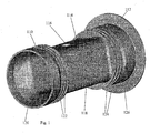
- the flow meter insert illustrated in Fig. 1 comprises an inlet section 110 and an outlet section 112 of substantially circular cross-section and a central measuring section 114 of substantially square cross-section.
- the inlet 110 and outlet 112 sections are of a similar cross-sectional shape to that of the flow conduit into which the insert is to be inserted, in this case they are circular.
- the dimensions of the inlet 110 and outlet 112 sections are such that these sections of the insert just fit within the flow conduit.
- Ribs 122, 124 may be provided on the outer surface of one or both of the inlet 110 and outlet 112 sections. The ribs may provide rigidity to the insert and may enable the insert to be fixed more securely to the fluid conduit.
- the insert may further be provided with one or more flanges.
- the insert of Fig. 1 comprises a flange 126 at one end of the insert.
- the flange 126 is formed integrally with the insert, but, in an alternative configuration, the flange may be coupled to the insert.
- the flange may allow the insert to be anchored securely to the flow conduit.
- the measuring section 114 of the example illustrated in Fig. 1 has a generally square cross-section. However, the corners of the square are rounded. This may allow the fluid to flow more smoothly through the measuring section 114.
- the measuring section 114 may have a cross-section of a different shape, for example the measuring section 114 may have a rectangular, hexagonal or octagonal cross-section.
- the measuring section 114 may have any number of sides and may include curved portions, but it is preferred if the section has at least two generally or substantially parallel sides.
- a transition region 120 is provided between the inlet section 110 and the measuring section 114 and between the measuring section 114 and the outlet section 112 so that a smooth transition may be provided between the cross-sectional shapes of the different sections. This may allow the fluid to flow smoothly through the measuring section 114. In an alternative configuration, the transition region 120 may be provided only between the inlet section 110 and the measuring section 114.
- Connecting portions 116, 118 may further be provided to allow electrodes and/or magnetic-field-producing means to be provided and operated to obtain a measurement of the fluid flow within the flow meter insert measuring section 118.
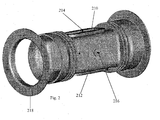
- Fig. 2 illustrates a further example of a flow meter insert in which magnetic field generating means 210, 212, in this case in the form of coils, are provided on the surface of the insert.
- the magnetic field generating means may be provided on the inside of the insert or on the outside of the flow conduit.
- Electrodes, or connectors for electrodes 214, 216, which may be positioned within or outside the insert, are further provided in the present example. Positive and/or negative electrodes may be provided and a ground electrode may further be provided.
- a further flange 218 is provided in the example of Fig. 2 .
- This flange 218 is detachable from the insert to allow the insert to be placed within the flow conduit, as discussed in more detail with reference to Fig. 3 .
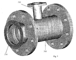
- Fig. 3 illustrates an insert positioned within a flow conduit 310.
- the insert is slid into the conduit and a flange 218 is coupled to the insert to retain the insert in place within the conduit.
- the flange 218 may also ensure that all of the fluid in the flow conduit passes within the insert.
- the flow conduit 310 further comprises an outlet 312 which may be used to provide power to the magnetic field generating means and to the electrodes within the flow conduit 310 and may be used to allow readings to be obtained from the equipment within the conduit.
- the insert On insertion into the flow conduit, the insert is preferably back-potted to support the insert and stabilise it within the flow conduit.
- Any suitable potting compound may be used, for example epoxy resin or polyurethane.
- the flow meter insert may be manufactured by injection moulding.
- the insert may be manufactured from a plastics material, such as ABS, from natural or synthetic rubber, or from another similar material.
- An insert manufactured from materials that are less affected by elevated temperatures or corrosive fluids may be manufactured from methods already used by these industries (including sintering, transfer moulding, rotational moulding etc). The methods of manufacture for these materials is slightly different to 'normal' plastics due to the viscoelastic properties of these materials at their processing temperatures.
- Other more conventional plastics that could be used for less demanding specialist applications such as HDPE or PVDF could be manufactured from more conventional techniques such as injection moulding.
- the insert 414 of the example described above may be inserted into a cylindrical pipe or fluid flow conduit 412 with the magnetic return circuit being made with the pipe or with a layer of silicon steel wrapped inside the pipe.
- the magnetic field within the insert may not be uniform throughout the insert, in fact, in some instances, the magnetic flux lines 416 may be facing in the wrong direction in the corners of the measuring section 410. This is due to two factors: firstly, the proximity of the return circuit 412 (the flow conduit in Fig. 4 ) to the edge of the pole piece plate and secondly the amount of room for the magnetic pole piece 418 and coil 420.
- the corners of the insert 510 may be filled with material to make a flow measuring section almost in the shape of a 'Maltese cross'.
- This embodiment may alleviate the non-uniform field problem by ensuring that the fluid only passes through the uniform field sections.
- An insert for an electromagnetic flow meter arranged to be positioned within a flow conduit having a flow conduit cross-section to define a flow path for fluid, wherein the insert comprises an inlet, a measuring section with a measuring cross-section different to the flow conduit cross-section and having at least two substantially parallel sides over at least part of its length and an outlet.
Landscapes
- Physics & Mathematics (AREA)
- Electromagnetism (AREA)
- Fluid Mechanics (AREA)
- General Physics & Mathematics (AREA)
- Measuring Volume Flow (AREA)
Description
- The present invention relates to the field of electromagnetic flow meters, in particular, to the field of insert to define a fluid flow path within an electromagnetic flow meter.
- Electromagnetic flow meters may be used to determine the rate of flow of fluid in a conduit. The conduit itself may be used to define the fluid path within the flow meter or an insert, placed within the conduit, may define the fluid path within the flow measurement zone.
- Prior art flow meters, or flow meter inserts, generally have a substantially circular cross-section, which may be designed to match the cross-section of the fluid conduit. Circular cross-section inserts may be manufactured easily and may provide an effective way to contain the fluid, which may be under pressure. The walls of the circular fluid conduit may further be used to support the flow meter insert and, since it is not required to be self-supporting, the flow meter insert may be manufactured economically as a lightweight insert.
WO 00/47954 A1 GB 2 328 021 A - A disadvantage of such flow meters or flow meter inserts, however, is that, due to their generally circular cross-sections, approximations must be made in determining the flow rate of the fluid, they require typically 5-10 diameters of upstream pipe work to ensure an accurate measurement or they are susceptible to the pipe work conditions in surrounding the installation.
- Flow meters or flow meter inserts with substantially square or rectangular cross-sections have been designed for specialist purposes for which a measurement with immunity to flow conditions is required. Such flow meters may provide improved performance when compared to the standard circular cross-section flow meters, but they tend to be bulky to provide the strength required to form a flow conduit and hence are not suitable as general-purpose flow meters.
GB 2 081 449 A US 6 237 424 B1 ,JP 58 085118 A JP 4 295722 A - The present invention is an elongate moulded insert as defined in Claim 1 of the appended claims. Also provided is a method of manufacturing an elongate insert by moulding, as defined in Claim 8, an electromagnetic flow meter as defined in Claim 11, and a method of manufacturing an electromagnetic flow meter as defined in Claim 12.
- A first aspect provides an insert for an electromagnetic flow meter arranged to be positioned within a flow conduit having a flow conduit cross-section to define a flow path for fluid, wherein the insert comprises an inlet, a measuring section with a measuring cross-section different to the flow conduit cross-section and having at least two substantially parallel sides over at least part of its length and an outlet.
- Using flow meter inserts with at least two substantially parallel sides may also advantageously improve the accuracy of the flow meter readings since such flow meters may be closer to a theoretically ideal flow meter, that is a flow meter with a uniform weight function. This may allow accurate measurements to be obtained even in low hydraulic performance cases. Having at least two substantially parallel sides may also increase the available space for the electrodes and decrease the pressure drops. In addition, the hydraulic performance of the meter may be improved so that the meter may be less sensitive to how it is installed and may provide a higher performance in a non-optimal installation. Also, for a given geometry, the magnetic field may be increased by using an insert with at least two substantially parallel sides. This may allow the coil of the flow meter to be used more efficiently so that a more economical coil may be used and/or less power may be used to drive the coils.
- Preferably, the insert further comprises a transition section between at least one of the inlet and the outlet and the measuring section wherein the cross-sectional shape of the insert transforms smoothly from the shape of the inlet and/or the outlet to the shape of the measuring section in the transition section.
- Hence a smooth transition between the shapes of the two sections may be provided. This may minimise the disturbance of the flow caused by the changing shape of the conduit and may allow a more accurate flow rate measurement to be obtained. The inlet and/or outlet sections comprise a substantially circular cross-section. Hence the inlet and/or outlet sections have a cross-sectional shape corresponding to that of a circular conduit.
In one embodiment, the cross-sectional area of the measuring section may cover at least 70% of the cross-sectional area of the flow conduit. Further, the cross-sectional area of the measuring section may cover at least 80% of the cross-sectional area of the flow conduit.
In an alternative embodiment, the cross-sectional area of the measuring section may cover less than around 50% of the cross-sectional area of the flow conduit. This may be useful in a low flow rate system or to increase the uniformity of the magnetic field in the measuring section, as discussed in more detail below.
Preferably, the insert is manufactured by injection moulding, transfer moulding or rotational moulding. Moulding the flow meter insert, from a material such as a plastics or rubber material may allow non-circular flow meter inserts to be provided that are lightweight and economical but that are strong and robust enough to maintain their integrity under fluid pressure.
In one embodiment, the insert may be manufactured substantially from a thermoplastic material; for example, the insert may be manufactured from a glass-loaded plastics material. Preferably, the insert may be manufactured from ABS (acrylonitrile butadiene styrene). Alternatively, the insert may be manufactured from another similar material, such as another polymer material, another plastics material or natural or synthetic rubber, such as a soft rubber material or a hard rubber material.
In an alternative embodiment, the insert may be manufactured from a fluorocarbon material such as PTFE (Teflon (RTM)) or ETFE or the insert may be manufactured from PVDF. - The insert may also be manufactured as a flexible rubber insert.
- According to a further embodiment, the insert may be manufactured substantially from a thermoset material.
- Preferably, the insert may be manufactured substantially from a reinforced thermoset material.
- According to a further preferable embodiment, the insert may be manufactured substantially from a reinforced thermoplastics material; for example, the insert may be manufactured from a fibreglass material.
- The insert may be bonded to backpotting, which may be provided to give the insert the strength and rigidity required under fluid pressure. The method of manufacture of the insert is preferably selected based on the material used for the insert and the most suitable method for the particular material selected, which may be a prior art method, may be used.
- Preferably, the cross-sectional size and/or shape of the insert may be arranged so that a substantially uniform magnetic field may be applied over substantially the whole cross-sectional area of the measuring section insert. As discussed in more detail below, this may advantageously allow a more accurate measurement of the flow rate to be determined. In some embodiments, this may be achieved, for example by infilling the corners of a substantially square insert.
- In one embodiment, the insert may be formed in more than one piece.
- The flow meter in which the insert may be deployed may be a wetted-type or a capacitive-type flow meter.
- The electrodes of the flow meter may be provided integrally with the insert or may be provided as a separate component, for example they may be coupled to the insert. The electrodes may comprise metallic or conductive plastics electrodes. A variety of electrode configurations may be used in conjunction with the insert and the electrode configuration used may be determined, at least in part, by the cross-section of the insert.
- Similarly, the magnetic field generating means may be provided integrally with or may be coupled to the insert. The magnetic field generating means may comprise a magnetic circuit. The magnetic field generating means or magnetic circuit may be provided internally or externally of the insert.
- In one embodiment, an electrostatic screen may be provided as part of or in addition to the insert.
- Preferably, the insert is back-potted on insertion into a flow conduit. Back-potting may allow the insert to be supported and stabilised within the conduit and hence may increase the reliability of the flow measurements.
- A further aspect provides a method of manufacturing an insert for an electromagnetic flow meter comprising forming an insert by moulding wherein the insert is formed such that the insert has a conduit therethrough and comprises an inlet, a measuring section with a cross-section having at least two substantially parallel sides over at least part of its length and an outlet.
- Forming the insert using the methods described herein may allow a robust but lightweight insert to be formed.
- In one embodiment, the insert is formed from a shape-memory material.
- Preferably, the insert is formed substantially from a thermoplastic material; for example, the insert may be manufactured from a glass-loaded plastics material.
- In a further preferable embodiment, the insert is formed substantially from ABS (acrylonitrile butadiene styrene)
- In one embodiment, the insert is formed substantially from a plastics material, such as PTFE or PVDF, or from natural or synthetic rubber, such as a soft rubber material.
- According to a further embodiment, the insert may be manufactured substantially from a thermoset material.
- Preferably, the insert may be manufactured substantially from a reinforced thermoset material.
- According to a further preferable embodiment, the insert may be manufactured substantially from a reinforced thermoplastics material; for example, the insert may be manufactured from a fibreglass material.
- A further aspect provides an electromagnetic flow meter comprising:
- a section of flow conduit;
- an insert according to the first aspect or any of its preferred features.
- The insert may allow the electromagnetic flow meter to be assembled reliably and efficiently.
- A further aspect provides a method of manufacturing a flow meter comprising:
- inserting an insert according to the first aspect into a flow conduit; and
- back-potting the insert to support the insert within the flow conduit.
- In one embodiment, the method further comprises providing magnetic field generating means and/or electrodes in conjunction with the insert. The magnetic field generating means and/or the electrodes may be provided integrally with or separately from the insert. The magnetic field generating means and the electrodes may be provided within or outside the flow conduit.
- The method may further comprise providing an electrostatic screen in conjunction with the insert. The screen may be formed integrally with the insert or may be coupled to the insert before the insert is placed within the flow conduit.
- The flow meter may be a wetted-type or a capacitive-type flow meter.
- Preferably, the insert is arranged within the flow conduit so that a substantially uniform magnetic field is provided across substantially the whole cross-sectional area of the measuring section of the insert.
- This feature may be provided by obscuring from the fluid regions of the insert where the magnetic field is not uniform.
- A skilled person will appreciate that variations of detail may be provided and features of one aspect may be applied to other aspects within the scope of the invention as set out in the claims.
- Embodiments of the flow meter insert will now be described with reference to the drawings in which:
-
Fig. 1 illustrates one example of a flow meter insert; -
Fig. 2 illustrates a further example of an insert; -
Fig. 3 is a schematic diagram of an insert inserted into a flow conduit; -
Fig. 4 is a schematic cross-sectional diagram of a substantially square section insert; and -
Fig. 5 is a schematic cross-sectional diagram of a substantially square section insert with infilled corner sections according to an embodiment. - The flow meter insert illustrated in
Fig. 1 comprises aninlet section 110 and anoutlet section 112 of substantially circular cross-section and acentral measuring section 114 of substantially square cross-section. Theinlet 110 andoutlet 112 sections are of a similar cross-sectional shape to that of the flow conduit into which the insert is to be inserted, in this case they are circular. The dimensions of theinlet 110 andoutlet 112 sections are such that these sections of the insert just fit within the flow conduit.Ribs inlet 110 andoutlet 112 sections. The ribs may provide rigidity to the insert and may enable the insert to be fixed more securely to the fluid conduit. - The insert may further be provided with one or more flanges. The insert of
Fig. 1 comprises aflange 126 at one end of the insert. In this example, theflange 126 is formed integrally with the insert, but, in an alternative configuration, the flange may be coupled to the insert. The flange may allow the insert to be anchored securely to the flow conduit. - The measuring
section 114 of the example illustrated inFig. 1 has a generally square cross-section. However, the corners of the square are rounded. This may allow the fluid to flow more smoothly through the measuringsection 114. In alternative configurations, the measuringsection 114 may have a cross-section of a different shape, for example the measuringsection 114 may have a rectangular, hexagonal or octagonal cross-section. The measuringsection 114 may have any number of sides and may include curved portions, but it is preferred if the section has at least two generally or substantially parallel sides. - In the insert of
Fig. 1 , atransition region 120 is provided between theinlet section 110 and themeasuring section 114 and between the measuringsection 114 and theoutlet section 112 so that a smooth transition may be provided between the cross-sectional shapes of the different sections. This may allow the fluid to flow smoothly through the measuringsection 114. In an alternative configuration, thetransition region 120 may be provided only between theinlet section 110 and themeasuring section 114. - Connecting
portions insert measuring section 118. -
Fig. 2 illustrates a further example of a flow meter insert in which magnetic field generating means 210, 212, in this case in the form of coils, are provided on the surface of the insert. In alternative configurations, the magnetic field generating means may be provided on the inside of the insert or on the outside of the flow conduit. - Electrodes, or connectors for
electrodes - A
further flange 218 is provided in the example ofFig. 2 . Thisflange 218 is detachable from the insert to allow the insert to be placed within the flow conduit, as discussed in more detail with reference toFig. 3 . -
Fig. 3 illustrates an insert positioned within aflow conduit 310. The insert is slid into the conduit and aflange 218 is coupled to the insert to retain the insert in place within the conduit. Theflange 218 may also ensure that all of the fluid in the flow conduit passes within the insert. - In the example of
Fig. 3 , theflow conduit 310 further comprises anoutlet 312 which may be used to provide power to the magnetic field generating means and to the electrodes within theflow conduit 310 and may be used to allow readings to be obtained from the equipment within the conduit. - On insertion into the flow conduit, the insert is preferably back-potted to support the insert and stabilise it within the flow conduit. Any suitable potting compound may be used, for example epoxy resin or polyurethane.
- The flow meter insert may be manufactured by injection moulding. The insert may be manufactured from a plastics material, such as ABS, from natural or synthetic rubber, or from another similar material.
- An insert manufactured from materials that are less affected by elevated temperatures or corrosive fluids (such as PTFE, PFA, i.e. 'Teflon' family) may be manufactured from methods already used by these industries (including sintering, transfer moulding, rotational moulding etc). The methods of manufacture for these materials is slightly different to 'normal' plastics due to the viscoelastic properties of these materials at their processing temperatures. Other more conventional plastics that could be used for less demanding specialist applications such as HDPE or PVDF could be manufactured from more conventional techniques such as injection moulding.
- A development of the insert described above is to arrange the insert so that a perfectly uniform magnetic field is provided throughout the measuring section. With reference to
Fig. 4 , theinsert 414 of the example described above may be inserted into a cylindrical pipe orfluid flow conduit 412 with the magnetic return circuit being made with the pipe or with a layer of silicon steel wrapped inside the pipe. As illustrated inFig. 4 at 410, the magnetic field within the insert may not be uniform throughout the insert, in fact, in some instances, themagnetic flux lines 416 may be facing in the wrong direction in the corners of the measuringsection 410. This is due to two factors: firstly, the proximity of the return circuit 412 (the flow conduit inFig. 4 ) to the edge of the pole piece plate and secondly the amount of room for themagnetic pole piece 418 andcoil 420. - Having a non-uniform magnetic field throughout the insert may have an adverse affect on the performance of the sensor or flow meter. A number of developments may be implemented to improve this design problem.
- As illustrated schematically in
Fig. 5 , the corners of theinsert 510 may be filled with material to make a flow measuring section almost in the shape of a 'Maltese cross'. This embodiment may alleviate the non-uniform field problem by ensuring that the fluid only passes through the uniform field sections. - Alternative configurations of the insert and the pressure containment vessel may be implemented to keep the magnetic field substantially uniform within the measuring section and such configurations would be obvious to one skilled in the art.
- The description above is provided by way of illustration only and further modifications and variations of detail would be obvious to one skilled in the art.
- Each feature disclosed in this specification (which term includes the claims) and/or shown in the drawings may be incorporated in the invention independently of other disclosed and/or illustrated features.
- Statements in this specification of the "objects of the invention" relate to preferred embodiments of the invention, but not necessarily to all embodiments of the invention falling within the claims.
- The description of the invention with reference to the drawings is by way of example only. The text of the abstract filed herewith is repeated here as part of the specification.
- An insert for an electromagnetic flow meter arranged to be positioned within a flow conduit having a flow conduit cross-section to define a flow path for fluid, wherein the insert comprises an inlet, a measuring section with a measuring cross-section different to the flow conduit cross-section and having at least two substantially parallel sides over at least part of its length and an outlet.
Claims (15)
- An elongate moulded insert adapted for longitudinal insertion along and within an elongate flow conduit of an electromagnetic flow meter, the flow conduit having a generally circular cross-sectional shape, the moulded insert having a conduit therethrough extending along its longitudinal axis and along which fluid can flow along a flow path, the moulded insert comprising:i) an inlet (110) for receiving fluid flowing along said flow conduit, the inlet (110) having a generally circular cross-sectional shape in a direction transverse to the longitudinal axis of the insert, for fitting within the flow conduit into which the insert is adapted to be inserted;ii) an outlet (112) for outputting fluid that flows through said insert, the outlet (112) having a generally circular cross-sectional shape in a direction transverse to the longitudinal axis of the insert, for fitting within the flow conduit into which the insert is adapted to be inserted; andiii) a measuring section (114) positioned between said inlet (110) and said outlet (112), said measuring section (114) having an inner surface which defines a measuring channel through which fluid from said inlet (110) can flow,characterised in that
said inner surface has at least two substantially parallel sides which extend along said flow path so that said measuring channel has a cross-section in a direction transverse to said flow path which is different to that of the flow conduit, and that said cross-section of the measuring channel is in the shape of a hexagon or an octagon, or substantially a square with infilled corners. - An insert according to Claim 1 further comprising a transition section (120) between the inlet (110) and the measuring section (114) and a transition section between the outlet (112) and the measuring section (114), wherein the cross-sectional shape of the insert transforms smoothly from the shape of the inlet (110) and the outlet (112) to the shape of the measuring section (114) in the transition sections.
- An insert according to Claim 1 or Claim 2 wherein the cross-sectional area of the measuring section (114) covers less than around 50% of the cross-sectional area of the flow conduit.
- An insert according to any preceding claim wherein the insert is manufactured substantially from one of a thermoplastic material or acrylonitrile butadiene styrene, ABS, or a soft rubber material or a hard rubber material, or PTFE or PVDF, or thermoset material, or a reinforced thermoset material, or a reinforced thermoplastics material.
- An insert according to any preceding claim wherein the cross-sectional size and/or shape of the insert are arranged so that a substantially uniform magnetic field may be applied over substantially the whole cross-sectional area of the measuring section (114) of the insert.
- An insert according to any preceding claim wherein the insert is formed in more than one piece.
- An insert according to any preceding claim further comprising electrodes and/or magnetic field generating means and/or an electrostatic screen provided integrally with the insert or coupled to the insert.
- A method of manufacturing an elongate insert adapted for longitudinal insertion along and within an elongate flow conduit of an electromagnetic flow meter, the flow conduit having a generally circular cross-sectional shape, the method comprising forming the elongate insert by moulding, wherein the elongate insert is formed such that the insert has a conduit therethrough extending along its longitudinal axis and along which fluid can flow along a flow path and the method comprises moulding the insert to have:i) an inlet (110) for receiving fluid flowing along said flow conduit, the inlet (110) having a generally circular cross-sectional shape in a direction transverse to the longitudinal axis of the insert, for fitting within the flow conduit into which the insert is adapted to be inserted;ii) an outlet (112) for outputting fluid that flows through said insert, the outlet (112) having a generally circular cross-sectional shape in a direction transverse to the longitudinal axis of the insert, for fitting within the flow conduit into which the insert is adapted to be inserted; andiii) a measuring section (114) positioned between said inlet (110) and said outlet (112), said measuring section (114) having an inner surface which defines a measuring channel through which fluid from said inlet (110) can flow,characterised in that
said inner surface has at least two substantially parallel sides which extend along said flow path so that said measuring section has a cross-section in a direction transverse to the longitudinal axis of the insert which is different from that of the inlet and the outlet, and that said cross-section of the measuring channel is in the shape of a hexagon or an octagon, or substantially a square with infilled corners. - A method according to Claim 8 wherein the insert is formed from a shape-memory material.
- A method according to Claim 8 or Claim 9 wherein the insert is formed substantially from one of a thermoplastic material, or acrylonitrile butadiene styrene, ABS, or PTFE or PVDF, or a soft rubber material, or a hard rubber material, or a thermoset material, or a reinforced thermoset material, or a reinforced thermoplastics material.
- An electromagnetic flow meter comprising:a section of a flow conduit; andan insert according to any of Claims 1 to 7 or made by a method according to any of Claims 8 to 10.
- A method of manufacturing an electromagnetic flow meter comprising:inserting an insert according to any of Claims 1 to 7 into an elongate flow conduit; andback-potting the insert to support the insert within the flow conduit.
- A method according to Claim 12 further comprising providing magnetic field generating means and/or electrodes, and/or an electrostatic screen in conjunction with the insert.
- A method according to Claim 12 or Claim 13 wherein the flow meter is a wetted-type or a capacitive-type flow meter.
- A method according to any of Claims 12 to 14 wherein the insert is arranged within the flow conduit so that a substantially uniform magnetic field is provided across substantially the whole cross-sectional area of the measuring section (114) of the insert.
Applications Claiming Priority (2)
| Application Number | Priority Date | Filing Date | Title |
|---|---|---|---|
| GBGB0329450.1A GB0329450D0 (en) | 2003-12-19 | 2003-12-19 | Electromagnetic flow meter insert |
| GB0329450 | 2003-12-19 |
Publications (2)
| Publication Number | Publication Date |
|---|---|
| EP1544582A1 EP1544582A1 (en) | 2005-06-22 |
| EP1544582B1 true EP1544582B1 (en) | 2017-10-11 |
Family
ID=30776111
Family Applications (1)
| Application Number | Title | Priority Date | Filing Date |
|---|---|---|---|
| EP04257976.3A Expired - Lifetime EP1544582B1 (en) | 2003-12-19 | 2004-12-20 | Electromagnetic flow meter insert |
Country Status (4)
| Country | Link |
|---|---|
| US (1) | US7228748B2 (en) |
| EP (1) | EP1544582B1 (en) |
| AU (1) | AU2004240232B2 (en) |
| GB (2) | GB0329450D0 (en) |
Cited By (2)
| Publication number | Priority date | Publication date | Assignee | Title |
|---|---|---|---|---|
| WO2022079213A1 (en) | 2020-10-14 | 2022-04-21 | Gwf Messsysteme Ag | Flowmeter |
| EP4644845A1 (en) | 2024-04-29 | 2025-11-05 | Gwf Ag | Flow meter |
Families Citing this family (18)
| Publication number | Priority date | Publication date | Assignee | Title |
|---|---|---|---|---|
| US7650797B2 (en) * | 2005-03-14 | 2010-01-26 | Siemens Aktiengesellschaft | Tubular insert for a magnetic induction flow meter |
| DE102006008433B4 (en) * | 2006-02-23 | 2010-12-23 | Abb Ag | Magnetic-inductive flowmeter with a measuring tube made of plastic |
| GB2440963B (en) | 2006-08-18 | 2011-06-08 | Abb Ltd | Flow meter |
| GB2440964B (en) * | 2006-08-18 | 2011-08-10 | Abb Ltd | Flow meter |
| DE102006060446A1 (en) * | 2006-12-19 | 2008-06-26 | Endress + Hauser Flowtec Ag | Device for measuring the volume or mass flow of a medium in a pipeline |
| DE102008057756A1 (en) * | 2008-11-17 | 2010-05-27 | Krohne Ag | Magnetic-inductive flowmeter |
| DE102008057755B4 (en) * | 2008-11-17 | 2015-12-17 | Krohne Ag | Magnetic-inductive flowmeter |
| DE102009001413A1 (en) * | 2009-03-09 | 2010-09-16 | Ifm Electronic Gmbh | Coil assembly for use in magnetic inductive flow-meter used in e.g. hardening system for measuring flow of water, has flat planar coupling plates, where field line density in plates is smaller than field line density in coil cores |
| DE102010031433A1 (en) | 2010-07-16 | 2012-01-19 | Endress + Hauser Flowtec Ag | Insert for magnetically-inductive flow meter for volumetric flow measurement of medium, has transfer electrode electrically contacting measuring electrode of flow meter at mounting state of insert at measuring pipe of flow meter |
| MX2011009315A (en) * | 2010-09-06 | 2012-03-15 | Mr Technologies S A | Precision fluid flow meter for reduced flows. |
| DE102012111757B4 (en) * | 2012-12-04 | 2022-05-19 | Sartorius Stedim Biotech Gmbh | Device for flow measurement in hose and/or plastic pipe systems |
| DE102014119451A1 (en) * | 2014-12-22 | 2016-06-23 | Endress+Hauser Flowtec Ag | Magnetic-inductive flowmeter |
| DE102015116679A1 (en) * | 2015-01-14 | 2016-07-14 | Krohne Ag | Magnetic-inductive flowmeter |
| CN105157767A (en) * | 2015-05-22 | 2015-12-16 | 姜跃炜 | Electromagnetic flow transducer |
| US10502599B2 (en) * | 2016-03-31 | 2019-12-10 | Rosemount Inc. | Polymeric magnetic flowmeter flow body assembly |
| US10052441B2 (en) * | 2016-08-02 | 2018-08-21 | Becton, Dickinson And Company | System and method for measuring delivered dose |
| DE102018112897A1 (en) * | 2018-05-30 | 2019-12-05 | Krohne Messtechnik Gmbh | Magnetic-inductive flowmeter and measuring tube |
| US11009423B2 (en) * | 2018-08-13 | 2021-05-18 | The Boeing Company | External leak detection system to detect a leak in a conduit |
Citations (4)
| Publication number | Priority date | Publication date | Assignee | Title |
|---|---|---|---|---|
| JPS5885118A (en) * | 1981-11-14 | 1983-05-21 | Yokogawa Hokushin Electric Corp | Electromagnetic flowmeter |
| JPH04295722A (en) * | 1991-03-25 | 1992-10-20 | Aichi Tokei Denki Co Ltd | Residual magnetic electromagnetic flowmeter |
| GB2328021A (en) * | 1997-08-01 | 1999-02-10 | Abb Kent Taylor Ltd | Electromagnetic flow sensor and assembly method |
| WO2000047954A1 (en) * | 1999-02-12 | 2000-08-17 | Danfoss A/S | Electromagnetic flow meter and method for producing same |
Family Cites Families (15)
| Publication number | Priority date | Publication date | Assignee | Title |
|---|---|---|---|---|
| DE3013035A1 (en) * | 1979-04-05 | 1980-10-23 | Nat Res Dev | METHOD FOR ELECTROMAGNETIC FLOW MEASUREMENT AND WORKING FLOW MEASURING DEVICE |
| GB2081449B (en) | 1980-08-04 | 1984-09-26 | Aichi Tokei Denki Kk | Electromagnetic flow meters |
| US5150061A (en) * | 1989-05-23 | 1992-09-22 | Institut Francais Du Petrole | Method and device for measuring the qualities of a multiphase fluid |
| US5773723A (en) * | 1995-09-29 | 1998-06-30 | Lewis; Peter B. | Flow tube liner |
| GB2314902B (en) | 1996-06-24 | 2000-01-19 | Abb Kent Taylor Ltd | Flowmeter |
| DE19708857A1 (en) | 1996-12-20 | 1998-07-02 | Krohne Ag | Magnetic-inductive flow measuring device |
| GB2324606B (en) * | 1997-04-25 | 2002-01-16 | Kent Meters Ltd | Electromagnetic flowmeter |
| US6658720B1 (en) * | 1999-03-26 | 2003-12-09 | Endress + Hauser Flowtec Ag | Method of manufacturing an electromagnetic flow sensor |
| GB2358064A (en) | 2000-01-06 | 2001-07-11 | Abb Instrumentation Ltd | Flow meter structure |
| AU1005101A (en) | 2000-01-06 | 2001-07-12 | Abb Limited | Flow meter structure |
| DE10046195C2 (en) | 2000-09-19 | 2002-11-21 | Danfoss As | Use for a measuring tube of an inductive flow meter |
| GB2376529B (en) | 2001-02-06 | 2005-06-01 | Abb Metering Ltd | Electromagnetic flow meter |
| JP3953826B2 (en) | 2001-02-19 | 2007-08-08 | 株式会社日立製作所 | Insertion type electromagnetic current meter |
| GB2385667A (en) | 2002-02-26 | 2003-08-27 | Danfoss As | Insert for an inductive flowmeter |
| JP2004233203A (en) * | 2003-01-30 | 2004-08-19 | Yamatake Corp | Measuring tube for electromagnetic flow meter |
-
2003
- 2003-12-19 GB GBGB0329450.1A patent/GB0329450D0/en not_active Ceased
-
2004
- 2004-12-17 US US11/015,679 patent/US7228748B2/en not_active Expired - Lifetime
- 2004-12-20 EP EP04257976.3A patent/EP1544582B1/en not_active Expired - Lifetime
- 2004-12-20 AU AU2004240232A patent/AU2004240232B2/en not_active Ceased
- 2004-12-20 GB GB0427815A patent/GB2409525B/en not_active Expired - Fee Related
Patent Citations (4)
| Publication number | Priority date | Publication date | Assignee | Title |
|---|---|---|---|---|
| JPS5885118A (en) * | 1981-11-14 | 1983-05-21 | Yokogawa Hokushin Electric Corp | Electromagnetic flowmeter |
| JPH04295722A (en) * | 1991-03-25 | 1992-10-20 | Aichi Tokei Denki Co Ltd | Residual magnetic electromagnetic flowmeter |
| GB2328021A (en) * | 1997-08-01 | 1999-02-10 | Abb Kent Taylor Ltd | Electromagnetic flow sensor and assembly method |
| WO2000047954A1 (en) * | 1999-02-12 | 2000-08-17 | Danfoss A/S | Electromagnetic flow meter and method for producing same |
Cited By (3)
| Publication number | Priority date | Publication date | Assignee | Title |
|---|---|---|---|---|
| WO2022079213A1 (en) | 2020-10-14 | 2022-04-21 | Gwf Messsysteme Ag | Flowmeter |
| WO2022079214A1 (en) | 2020-10-14 | 2022-04-21 | Gwf Messsysteme Ag | Flowmeter |
| EP4644845A1 (en) | 2024-04-29 | 2025-11-05 | Gwf Ag | Flow meter |
Also Published As
| Publication number | Publication date |
|---|---|
| GB0427815D0 (en) | 2005-01-19 |
| AU2004240232A1 (en) | 2005-07-07 |
| GB2409525A (en) | 2005-06-29 |
| US7228748B2 (en) | 2007-06-12 |
| EP1544582A1 (en) | 2005-06-22 |
| US20050199073A1 (en) | 2005-09-15 |
| AU2004240232B2 (en) | 2009-07-23 |
| GB0329450D0 (en) | 2004-01-28 |
| GB2409525B (en) | 2007-03-28 |
Similar Documents
| Publication | Publication Date | Title |
|---|---|---|
| EP1544582B1 (en) | Electromagnetic flow meter insert | |
| US7665368B2 (en) | Flow meter | |
| US7621188B2 (en) | Flow meter | |
| CN101900583B (en) | Magnetic-inductive flow measuring apparatus | |
| CN107923776B (en) | Electromagnetic flow sensor | |
| EP2917700B1 (en) | Magnetoinductive flowmeter and arrangement | |
| US10429220B2 (en) | Magneto-inductive flow measuring device | |
| CN103134558B (en) | Magnetic-inductive flow measurement instrument | |
| US5852247A (en) | Apparatus for sensing liquid flow and pressure in a conduit or open channel and associated | |
| CN100468010C (en) | Tubular Inserts for Magnetic Induction Flow Meters | |
| WO2002063250A1 (en) | Flowmeter | |
| US20140230565A1 (en) | Magneto Inductive Flow Measuring Device | |
| CN101650203B (en) | Electromagnetic Flowmeter | |
| JP6373401B2 (en) | High pressure wafer type magnetic flow meter | |
| EP3566027B1 (en) | Ultrasonic sensor assembly with spiral flow path, and its method of manufacture | |
| US7318354B2 (en) | Magnetoinductive flowmeter with a two-part insert | |
| US5670724A (en) | Apparatus for sensing liquid flow and pressure in a conduit and associated methods | |
| GB2402219A (en) | Electromagnetic flow meter | |
| US5708213A (en) | Apparatus and associated method for sensing liquid flow and a liquid characteristic | |
| US5708212A (en) | Apparatus for sensing liquid flow rate and conditioning velocity profile and associated methods | |
| EP3628982B1 (en) | Full bore magnetic flowmeter assembly | |
| EP3568671B1 (en) | Fluid-flow sensor assembly having reinforced sensor body | |
| US20080029172A1 (en) | Integrated pressure proof fluid container with flexible pipe connectors | |
| US20260029262A1 (en) | Magnetic-inductive flow meter | |
| KR200485427Y1 (en) | Measuring device for liquid level |
Legal Events
| Date | Code | Title | Description |
|---|---|---|---|
| PUAI | Public reference made under article 153(3) epc to a published international application that has entered the european phase |
Free format text: ORIGINAL CODE: 0009012 |
|
| AK | Designated contracting states |
Kind code of ref document: A1 Designated state(s): AT BE BG CH CY CZ DE DK EE ES FI FR GB GR HU IE IS IT LI LT LU MC NL PL PT RO SE SI SK TR |
|
| AX | Request for extension of the european patent |
Extension state: AL BA HR LV MK YU |
|
| 17P | Request for examination filed |
Effective date: 20051219 |
|
| AKX | Designation fees paid |
Designated state(s): AT BE BG CH CY CZ DE DK EE ES FI FR GB GR HU IE IS IT LI LT LU MC NL PL PT RO SE SI SK TR |
|
| 17Q | First examination report despatched |
Effective date: 20120208 |
|
| GRAP | Despatch of communication of intention to grant a patent |
Free format text: ORIGINAL CODE: EPIDOSNIGR1 |
|
| INTG | Intention to grant announced |
Effective date: 20170502 |
|
| GRAS | Grant fee paid |
Free format text: ORIGINAL CODE: EPIDOSNIGR3 |
|
| GRAA | (expected) grant |
Free format text: ORIGINAL CODE: 0009210 |
|
| AK | Designated contracting states |
Kind code of ref document: B1 Designated state(s): AT BE BG CH CY CZ DE DK EE ES FI FR GR HU IE IS IT LI LT LU MC NL PL PT RO SE SI SK TR |
|
| RBV | Designated contracting states (corrected) |
Designated state(s): AT BE BG CH CY CZ DE DK EE ES FI FR GR HU IE IS IT LI LT LU MC NL PL PT RO SE SI SK TR |
|
| REG | Reference to a national code |
Ref country code: CH Ref legal event code: EP |
|
| REG | Reference to a national code |
Ref country code: IE Ref legal event code: FG4D |
|
| REG | Reference to a national code |
Ref country code: AT Ref legal event code: REF Ref document number: 936458 Country of ref document: AT Kind code of ref document: T Effective date: 20171115 |
|
| REG | Reference to a national code |
Ref country code: DE Ref legal event code: R096 Ref document number: 602004051898 Country of ref document: DE |
|
| REG | Reference to a national code |
Ref country code: FR Ref legal event code: PLFP Year of fee payment: 14 |
|
| REG | Reference to a national code |
Ref country code: NL Ref legal event code: MP Effective date: 20171011 |
|
| REG | Reference to a national code |
Ref country code: LT Ref legal event code: MG4D |
|
| REG | Reference to a national code |
Ref country code: AT Ref legal event code: MK05 Ref document number: 936458 Country of ref document: AT Kind code of ref document: T Effective date: 20171011 |
|
| PG25 | Lapsed in a contracting state [announced via postgrant information from national office to epo] |
Ref country code: NL Free format text: LAPSE BECAUSE OF FAILURE TO SUBMIT A TRANSLATION OF THE DESCRIPTION OR TO PAY THE FEE WITHIN THE PRESCRIBED TIME-LIMIT Effective date: 20171011 |
|
| PG25 | Lapsed in a contracting state [announced via postgrant information from national office to epo] |
Ref country code: ES Free format text: LAPSE BECAUSE OF FAILURE TO SUBMIT A TRANSLATION OF THE DESCRIPTION OR TO PAY THE FEE WITHIN THE PRESCRIBED TIME-LIMIT Effective date: 20171011 Ref country code: FI Free format text: LAPSE BECAUSE OF FAILURE TO SUBMIT A TRANSLATION OF THE DESCRIPTION OR TO PAY THE FEE WITHIN THE PRESCRIBED TIME-LIMIT Effective date: 20171011 Ref country code: SE Free format text: LAPSE BECAUSE OF FAILURE TO SUBMIT A TRANSLATION OF THE DESCRIPTION OR TO PAY THE FEE WITHIN THE PRESCRIBED TIME-LIMIT Effective date: 20171011 Ref country code: LT Free format text: LAPSE BECAUSE OF FAILURE TO SUBMIT A TRANSLATION OF THE DESCRIPTION OR TO PAY THE FEE WITHIN THE PRESCRIBED TIME-LIMIT Effective date: 20171011 |
|
| PG25 | Lapsed in a contracting state [announced via postgrant information from national office to epo] |
Ref country code: GR Free format text: LAPSE BECAUSE OF FAILURE TO SUBMIT A TRANSLATION OF THE DESCRIPTION OR TO PAY THE FEE WITHIN THE PRESCRIBED TIME-LIMIT Effective date: 20180112 Ref country code: AT Free format text: LAPSE BECAUSE OF FAILURE TO SUBMIT A TRANSLATION OF THE DESCRIPTION OR TO PAY THE FEE WITHIN THE PRESCRIBED TIME-LIMIT Effective date: 20171011 Ref country code: BG Free format text: LAPSE BECAUSE OF FAILURE TO SUBMIT A TRANSLATION OF THE DESCRIPTION OR TO PAY THE FEE WITHIN THE PRESCRIBED TIME-LIMIT Effective date: 20180111 Ref country code: IS Free format text: LAPSE BECAUSE OF FAILURE TO SUBMIT A TRANSLATION OF THE DESCRIPTION OR TO PAY THE FEE WITHIN THE PRESCRIBED TIME-LIMIT Effective date: 20180211 |
|
| REG | Reference to a national code |
Ref country code: DE Ref legal event code: R097 Ref document number: 602004051898 Country of ref document: DE |
|
| PG25 | Lapsed in a contracting state [announced via postgrant information from national office to epo] |
Ref country code: DK Free format text: LAPSE BECAUSE OF FAILURE TO SUBMIT A TRANSLATION OF THE DESCRIPTION OR TO PAY THE FEE WITHIN THE PRESCRIBED TIME-LIMIT Effective date: 20171011 Ref country code: EE Free format text: LAPSE BECAUSE OF FAILURE TO SUBMIT A TRANSLATION OF THE DESCRIPTION OR TO PAY THE FEE WITHIN THE PRESCRIBED TIME-LIMIT Effective date: 20171011 Ref country code: SK Free format text: LAPSE BECAUSE OF FAILURE TO SUBMIT A TRANSLATION OF THE DESCRIPTION OR TO PAY THE FEE WITHIN THE PRESCRIBED TIME-LIMIT Effective date: 20171011 Ref country code: CZ Free format text: LAPSE BECAUSE OF FAILURE TO SUBMIT A TRANSLATION OF THE DESCRIPTION OR TO PAY THE FEE WITHIN THE PRESCRIBED TIME-LIMIT Effective date: 20171011 |
|
| REG | Reference to a national code |
Ref country code: CH Ref legal event code: PL |
|
| PLBE | No opposition filed within time limit |
Free format text: ORIGINAL CODE: 0009261 |
|
| STAA | Information on the status of an ep patent application or granted ep patent |
Free format text: STATUS: NO OPPOSITION FILED WITHIN TIME LIMIT |
|
| PG25 | Lapsed in a contracting state [announced via postgrant information from national office to epo] |
Ref country code: PL Free format text: LAPSE BECAUSE OF FAILURE TO SUBMIT A TRANSLATION OF THE DESCRIPTION OR TO PAY THE FEE WITHIN THE PRESCRIBED TIME-LIMIT Effective date: 20171011 Ref country code: IT Free format text: LAPSE BECAUSE OF FAILURE TO SUBMIT A TRANSLATION OF THE DESCRIPTION OR TO PAY THE FEE WITHIN THE PRESCRIBED TIME-LIMIT Effective date: 20171011 Ref country code: RO Free format text: LAPSE BECAUSE OF FAILURE TO SUBMIT A TRANSLATION OF THE DESCRIPTION OR TO PAY THE FEE WITHIN THE PRESCRIBED TIME-LIMIT Effective date: 20171011 |
|
| 26N | No opposition filed |
Effective date: 20180712 |
|
| REG | Reference to a national code |
Ref country code: IE Ref legal event code: MM4A |
|
| PG25 | Lapsed in a contracting state [announced via postgrant information from national office to epo] |
Ref country code: LU Free format text: LAPSE BECAUSE OF NON-PAYMENT OF DUE FEES Effective date: 20171220 |
|
| REG | Reference to a national code |
Ref country code: BE Ref legal event code: MM Effective date: 20171231 |
|
| PG25 | Lapsed in a contracting state [announced via postgrant information from national office to epo] |
Ref country code: IE Free format text: LAPSE BECAUSE OF NON-PAYMENT OF DUE FEES Effective date: 20171220 |
|
| PG25 | Lapsed in a contracting state [announced via postgrant information from national office to epo] |
Ref country code: SI Free format text: LAPSE BECAUSE OF FAILURE TO SUBMIT A TRANSLATION OF THE DESCRIPTION OR TO PAY THE FEE WITHIN THE PRESCRIBED TIME-LIMIT Effective date: 20171011 Ref country code: CH Free format text: LAPSE BECAUSE OF NON-PAYMENT OF DUE FEES Effective date: 20171231 Ref country code: LI Free format text: LAPSE BECAUSE OF NON-PAYMENT OF DUE FEES Effective date: 20171231 Ref country code: BE Free format text: LAPSE BECAUSE OF NON-PAYMENT OF DUE FEES Effective date: 20171231 |
|
| PG25 | Lapsed in a contracting state [announced via postgrant information from national office to epo] |
Ref country code: HU Free format text: LAPSE BECAUSE OF FAILURE TO SUBMIT A TRANSLATION OF THE DESCRIPTION OR TO PAY THE FEE WITHIN THE PRESCRIBED TIME-LIMIT; INVALID AB INITIO Effective date: 20041220 Ref country code: MC Free format text: LAPSE BECAUSE OF FAILURE TO SUBMIT A TRANSLATION OF THE DESCRIPTION OR TO PAY THE FEE WITHIN THE PRESCRIBED TIME-LIMIT Effective date: 20171011 |
|
| PG25 | Lapsed in a contracting state [announced via postgrant information from national office to epo] |
Ref country code: CY Free format text: LAPSE BECAUSE OF NON-PAYMENT OF DUE FEES Effective date: 20171011 |
|
| PG25 | Lapsed in a contracting state [announced via postgrant information from national office to epo] |
Ref country code: TR Free format text: LAPSE BECAUSE OF FAILURE TO SUBMIT A TRANSLATION OF THE DESCRIPTION OR TO PAY THE FEE WITHIN THE PRESCRIBED TIME-LIMIT Effective date: 20171011 |
|
| PG25 | Lapsed in a contracting state [announced via postgrant information from national office to epo] |
Ref country code: PT Free format text: LAPSE BECAUSE OF FAILURE TO SUBMIT A TRANSLATION OF THE DESCRIPTION OR TO PAY THE FEE WITHIN THE PRESCRIBED TIME-LIMIT Effective date: 20171011 |
|
| PGFP | Annual fee paid to national office [announced via postgrant information from national office to epo] |
Ref country code: FR Payment date: 20211224 Year of fee payment: 18 Ref country code: DE Payment date: 20211210 Year of fee payment: 18 |
|
| REG | Reference to a national code |
Ref country code: DE Ref legal event code: R119 Ref document number: 602004051898 Country of ref document: DE |
|
| PG25 | Lapsed in a contracting state [announced via postgrant information from national office to epo] |
Ref country code: DE Free format text: LAPSE BECAUSE OF NON-PAYMENT OF DUE FEES Effective date: 20230701 |
|
| PG25 | Lapsed in a contracting state [announced via postgrant information from national office to epo] |
Ref country code: FR Free format text: LAPSE BECAUSE OF NON-PAYMENT OF DUE FEES Effective date: 20221231 |