EP1544988A1 - Coreless linear motor - Google Patents
Coreless linear motor Download PDFInfo
- Publication number
- EP1544988A1 EP1544988A1 EP03792669A EP03792669A EP1544988A1 EP 1544988 A1 EP1544988 A1 EP 1544988A1 EP 03792669 A EP03792669 A EP 03792669A EP 03792669 A EP03792669 A EP 03792669A EP 1544988 A1 EP1544988 A1 EP 1544988A1
- Authority
- EP
- European Patent Office
- Prior art keywords
- coil
- mounting table
- slider
- linear motor
- coils
- Prior art date
- Legal status (The legal status is an assumption and is not a legal conclusion. Google has not performed a legal analysis and makes no representation as to the accuracy of the status listed.)
- Granted
Links
Images

Classifications
-
- H—ELECTRICITY
- H02—GENERATION; CONVERSION OR DISTRIBUTION OF ELECTRIC POWER
- H02K—DYNAMO-ELECTRIC MACHINES
- H02K41/00—Propulsion systems in which a rigid body is moved along a path due to dynamo-electric interaction between the body and a magnetic field travelling along the path
- H02K41/02—Linear motors; Sectional motors
- H02K41/03—Synchronous motors; Motors moving step by step; Reluctance motors
- H02K41/031—Synchronous motors; Motors moving step by step; Reluctance motors of the permanent magnet type
-
- H—ELECTRICITY
- H02—GENERATION; CONVERSION OR DISTRIBUTION OF ELECTRIC POWER
- H02K—DYNAMO-ELECTRIC MACHINES
- H02K15/00—Processes or apparatus specially adapted for manufacturing, assembling, maintaining or repairing of dynamo-electric machines
- H02K15/10—Applying solid insulation to windings, stators or rotors, e.g. applying insulating tapes
- H02K15/105—Applying solid insulation to windings, stators or rotors, e.g. applying insulating tapes to the windings
-
- H—ELECTRICITY
- H02—GENERATION; CONVERSION OR DISTRIBUTION OF ELECTRIC POWER
- H02K—DYNAMO-ELECTRIC MACHINES
- H02K3/00—Details of windings
- H02K3/46—Fastening of windings on the stator or rotor structure
- H02K3/47—Air-gap windings, i.e. iron-free windings
-
- H—ELECTRICITY
- H02—GENERATION; CONVERSION OR DISTRIBUTION OF ELECTRIC POWER
- H02K—DYNAMO-ELECTRIC MACHINES
- H02K5/00—Casings; Enclosures; Supports
- H02K5/04—Casings or enclosures characterised by the shape, form or construction thereof
- H02K5/20—Casings or enclosures characterised by the shape, form or construction thereof with channels or ducts for flow of cooling medium
-
- H—ELECTRICITY
- H02—GENERATION; CONVERSION OR DISTRIBUTION OF ELECTRIC POWER
- H02K—DYNAMO-ELECTRIC MACHINES
- H02K5/00—Casings; Enclosures; Supports
- H02K5/04—Casings or enclosures characterised by the shape, form or construction thereof
- H02K5/22—Auxiliary parts of casings not covered by groups H02K5/06-H02K5/20, e.g. shaped to form connection boxes or terminal boxes
-
- H—ELECTRICITY
- H02—GENERATION; CONVERSION OR DISTRIBUTION OF ELECTRIC POWER
- H02K—DYNAMO-ELECTRIC MACHINES
- H02K9/00—Arrangements for cooling or ventilating
- H02K9/19—Arrangements for cooling or ventilating for machines with closed casing and closed-circuit cooling using a liquid cooling medium, e.g. oil
Definitions
- the present invention relates to a coreless linear motor for use in constant-speed feeding or highly accurate positioning which requires thrust ripple and low heat generation.
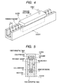
- FIG. 4 is a perspective view which shows only a slider and a stator of a coreless linear motor of the related art.
- Fig. 5 is a cross-sectional view as seen in a traveling direction of the slider.
- the stator 1 is made up of permanent magnets 2 which form a plurality of magnetic poles, back yokes 3 to which the plurality of permanent magnets are affixed and a yoke supporting table 4 which fixedly support the two back yokes 3 which are disposed on both left and right sides thereof along one side thereof.
- the permanent magnets 2 are disposed at a pitch of ⁇ such that the polarities of the permanent magnets 2 which face each other inwardly of the two back yokes 3 and the polarities of the permanent magnets 2 which are adjacent to each other in the traveling direction of the slider becomes different.
- the slider 10 is made up of an armature winding 11 and a slider mounting table 12 having a concave cross section in which the armature winding 11 is fixed. Since it is mounted on a table or the like which constitutes a load, the slider mounting table 12 is made of a metallic material such as aluminum which ensures a strength.
- the armature winding 11 is disposed in such a manner as to provide a predetermined gap between the permanent magnets 2 disposed on the interior side of each of the two back yokes 3 and itself.
- the armature winding 11 is made up of a plurality of coils 13.
- a coil end portion which corresponds to an upper side of the coil 13 is referred to as a coil upper side 14 and a coil end portion which corresponds to a lower side of the coil 13 is referred to as a coil lower side 15.
- the coils 13 are connected to each other via the coil upper sides 14 and distal ends of the coils 13 are connected with lead wires 16.
- a space for connecting the coils 13 to each other and a space for the lead wires 16 are provided in the concavity of the slider mounting table 12.
- the armature winding 11 and the interior of the concavity of the slider mounting table 12 are covered with a molded resin 17, so that the armature winding 11 and the slider mounting table 12 cooperate together to make up the slider 10.
- the slider is made to freely move in the traveling directions thereof by a supporting mechanism such as a linear guide, not shown.
- the molded resin 17 is filled in the wide concavity provided between the slider mounting table 12 and the coils 13 for the purpose of connecting process. Namely, the molded resin 17 constitutes a large thermal resistance, which disturbs the conduction of heat to the slider mounting table 12, and due to this, the increase in the temperature of the coils 13 became extremely large. While epoxy resin (having a heat conductivity of 1.5W/mK), which conducts heat well and contains, for example, alumina, has been used for the molded resin 17 with a view to preventing such a heat increase as much as possible, no sufficient effect has been obtained.
- the invention is made with a view to solving the problem, and an object thereof is to provide a coreless linear motor which can suppress the increase in the temperature of an armature winding.
- a coreless linear motor in which a slider is made up of an armature winding which comprises a plurality of coils and a slider mounting table which supports the armature winding and a stator is made up of permanent magnets which form a plurality of magnetic poles and back yokes, and, furthermore, in which both left and right sides of the armature winding is sandwiched by the permanent magnets via a gap,
- the coreless linear motor being characterized in that a concave portion is provided in a lower side of the slider mounting table, and in that a coil upper side which corresponds to an upper side of the coil is inserted in the interior of the concave portion in the slider mounting table and a space is provided in the vicinity of a coil lower side which corresponds to a lower side of the coil for performing a connecting process between the coils or the coil and a lead wire.
- a space for performing a connecting process is provided directly below the coil lower side.
- a space for performing a connecting process is provided on both left and right sides of the coil lower side.
- a cooling passageway is provided in the slider mounting table for the passage of a refrigerant or air.
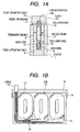
- Fig. 1 shows a coreless linear motor according to a first embodiment of the invention, in which Fig. 1A is a cross-sectional view of the coreless linear motor as seen in a traveling direction thereof, and Fig. 1B is a sectional view of a slider as seen from the side thereof.
- Fig. 2 is a corresponding view to Fig. 1A which shows a coreless linear motor according to a second embodiment of the invention.
- Fig. 3 is a corresponding view to Fig. 1A which shows a coreless linear motor according to a third embodiment of the invention.
- Fig. 4 is a perspective view of a coreless linear motor according to the related art.
- Fig. 5 is a corresponding view to Fig. 1A which shows the coreless linear motor according to the related art.
- the invention is similar to the construction shown in Figs. 4, 5 except for the construction of a slider thereof. Consequently, the description of a stator will be omitted.
- Figs. 1A, 1B are drawings showing a first embodiment, in which Fig. 1A is a cross-sectional view as seen in a traveling direction of a slider, and Fig. 1B is a sectional view of the slider as seen from the side thereof.
- the slider 10 in the first embodiment is made up of an armature winding 11 including a plurality of coils 13, a slider mounting table 12 in which the armature winding 11 is fixedly supported, lead wires 16 and a molded resin 17 which covers the armature winding 11 and the whole of the lead wires 16.
- the slider is shown as being made up of three coils of concentrated winding, which constitutes a minimum number of coils required. A space is provided directly below coil lower sides 15 of the three coils for performing the connection between the coils 13 or of the coils 13 with the lead wires 16.
- the slider mounting table 12 is made of a metallic material such as aluminum which can ensure a strength.
- the slider mounting table 12 is formed so as to have a concave cross-sectional shape, and coil upper sides 14 of the coils 13 are inserted into a concave portion so formed in the slider mounting table 12.
- the concave portion in the slider mounting table 12 is machined so as to have a channel which matches portions of the coil upper sides 14 which are inserted thereinto.
- the coil upper sides 14 can be made to approach the slider mounting table 12. Namely, the thermal resistance therebetween is made to become extremely small, so that heat generated in the coils 13 can easily escape to the slider mounting table 12. As a result, the increase in the temperature of the coils 13 can be suppressed largely.
- the second embodiment is such as to related to the third aspect of the invention.
- Fig. 2 shows a cross section as seen in the traveling direction of a slider.
- the second embodiment differs from the first embodiment in that the space for a connecting process is provided on the left and right sides of the coil lower sides 15. As a result, the cross section of a slider 10 becomes an I-shape.
- a further advantage of the second embodiment is that since the spaces for a connecting process are positioned directly below the permanent magnets 2, the dimension of the slider in the height direction can be reduced.
- the third embodiment is such as to relate to the fourth aspect of the invention.
- Fig. 3 is a cross section as seen in a traveling direction of a slider.
- the third embodiment differs from the first or third embodiment in that a refrigerant passageway 18 is provided in a slider mounting table 12 for the passage of a refrigerant or air.
- the invention can be applied to a technical field which produces and provides a coreless linear motor for use in constant-speed feeding or highly accurate positioning which requires thrust ripple and low heat generation.
Landscapes
- Engineering & Computer Science (AREA)
- Power Engineering (AREA)
- Physics & Mathematics (AREA)
- Chemical & Material Sciences (AREA)
- Combustion & Propulsion (AREA)
- Electromagnetism (AREA)
- Manufacturing & Machinery (AREA)
- Linear Motors (AREA)
- Motor Or Generator Cooling System (AREA)
Abstract
Description
Claims (4)
- A coreless linear motor comprising:a slider which is made up of an armature winding which includes a plurality of coils and a slider mounting table which supports the armature winding, anda stator which is made up of permanent magnets which form a plurality of magnetic poles and back yokes, whereinboth left and right sides of the armature winding is sandwiched by the permanent magnets via a gap,a concave portion is provided in a lower side of the slider mounting table,a coil upper side which corresponds to an upper side of the coil is inserted in the interior of the concave portion in the slider mounting table, anda space is provided in the vicinity of a coil lower side which corresponds to a lower side of the coil for performing a connecting process between the coils or the coil and a lead wire.
- The coreless linear motor as set forth in Claim 1, wherein
a space for performing a connecting process is provided directly below the coil lower side. - The coreless linear motor as set forth in Claim 1, wherein
a space for performing a connecting process is provided on both left and right sides of the coil lower side. - The coreless linear motor as set forth in any of Claims 1 to 3, further comprising:a cooling passageway provided in the slider mounting table for the passage of a refrigerant or air.
Applications Claiming Priority (3)
| Application Number | Priority Date | Filing Date | Title |
|---|---|---|---|
| JP2002239618 | 2002-08-20 | ||
| JP2002239618A JP3870413B2 (en) | 2002-08-20 | 2002-08-20 | Coreless linear motor |
| PCT/JP2003/010234 WO2004019470A1 (en) | 2002-08-20 | 2003-08-11 | Coreless linear motor |
Publications (3)
| Publication Number | Publication Date |
|---|---|
| EP1544988A1 true EP1544988A1 (en) | 2005-06-22 |
| EP1544988A4 EP1544988A4 (en) | 2008-07-02 |
| EP1544988B1 EP1544988B1 (en) | 2010-04-21 |
Family
ID=31943864
Family Applications (1)
| Application Number | Title | Priority Date | Filing Date |
|---|---|---|---|
| EP03792669A Expired - Lifetime EP1544988B1 (en) | 2002-08-20 | 2003-08-11 | Coreless linear motor |
Country Status (8)
| Country | Link |
|---|---|
| US (1) | US7531923B2 (en) |
| EP (1) | EP1544988B1 (en) |
| JP (1) | JP3870413B2 (en) |
| KR (1) | KR100785192B1 (en) |
| CN (1) | CN100438281C (en) |
| DE (1) | DE60332251D1 (en) |
| TW (1) | TWI288521B (en) |
| WO (1) | WO2004019470A1 (en) |
Cited By (3)
| Publication number | Priority date | Publication date | Assignee | Title |
|---|---|---|---|---|
| WO2009019192A1 (en) * | 2007-08-03 | 2009-02-12 | Siemens Aktiengesellschaft | Primary part of an electric linear motor with a cooling device |
| CN102142761A (en) * | 2010-02-02 | 2011-08-03 | 未来产业株式会社 | Mover for linear motor and manufacturing method thereof, linear motor comprising motor |
| EP2808986A1 (en) * | 2013-05-27 | 2014-12-03 | Etel S. A.. | Cooling body for a linear motor |
Families Citing this family (31)
| Publication number | Priority date | Publication date | Assignee | Title |
|---|---|---|---|---|
| JP3870413B2 (en) * | 2002-08-20 | 2007-01-17 | 株式会社安川電機 | Coreless linear motor |
| JP4672315B2 (en) | 2004-09-06 | 2011-04-20 | 東芝機械株式会社 | Linear motor and linear moving stage device |
| JP4886355B2 (en) * | 2006-05-02 | 2012-02-29 | 日本トムソン株式会社 | Slide device with built-in movable magnet type linear motor |
| JP5240543B2 (en) * | 2007-03-28 | 2013-07-17 | 日立金属株式会社 | Assembly method of moving coil type linear motor |
| JP4819745B2 (en) * | 2007-05-08 | 2011-11-24 | 住友重機械工業株式会社 | Linear motor and method for manufacturing linear motor |
| TWI408873B (en) * | 2010-01-25 | 2013-09-11 | Chieftek Prec Co Ltd | Linear motor coil assembly construction |
| US8154156B2 (en) | 2010-03-16 | 2012-04-10 | Chieftek Precision Co., Ltd. | Coil assembly for linear motor |
| CN102201713B (en) * | 2010-03-22 | 2015-05-13 | 直得科技股份有限公司 | Linear motor coil assembly structure |
| CN101976927B (en) * | 2010-10-28 | 2012-07-11 | 哈尔滨工业大学 | High-precision efficient straight reciprocating driving system |
| US8922068B2 (en) * | 2011-07-11 | 2014-12-30 | Baldor Electric Company | Linear drive motor with improved bearing system |
| US8791608B2 (en) * | 2011-07-11 | 2014-07-29 | Baldor Electric Company | Primary for linear drive motor with solid steel stacks |
| JP5648873B2 (en) | 2013-01-24 | 2015-01-07 | 株式会社安川電機 | Linear motor |
| JP6067421B2 (en) * | 2013-03-01 | 2017-01-25 | 住友重機械工業株式会社 | Linear motor |
| CN104702012B (en) * | 2013-12-10 | 2017-05-31 | 上海微电子装备有限公司 | Loop construction and linear electric motors |
| TWI514725B (en) * | 2013-12-19 | 2015-12-21 | Delta Electronics Inc | Linear motor and motor set using same |
| CN103997186B (en) * | 2014-06-06 | 2017-10-03 | 肖俊东 | Linear motor, disk type rotating motor and motor platform |
| US9996071B2 (en) * | 2014-06-24 | 2018-06-12 | Western Digital Technologies, Inc. | Moveable slider for use in a device assembly process |
| JP6318945B2 (en) * | 2014-07-24 | 2018-05-09 | 株式会社安川電機 | Coreless linear motor armature, coreless linear motor, and manufacturing method of coreless linear motor armature |
| CN105634240A (en) * | 2014-10-28 | 2016-06-01 | 鸿富锦精密工业(深圳)有限公司 | linear motor |
| JP2016171739A (en) * | 2015-03-09 | 2016-09-23 | 住友重機械工業株式会社 | Linear motor and stage device |
| EP3324521B1 (en) * | 2016-11-16 | 2020-04-15 | Etel S. A.. | Cooling plate for a linear motor |
| EP3457530B1 (en) | 2017-09-18 | 2021-11-24 | Etel S.A. | Set of parts, secondary part, and ironless linear motor |
| EP3471245B1 (en) | 2017-10-12 | 2020-11-18 | Etel S.A. | Secondary part for an ironless linear motor and ironless linear motor |
| EP3567708B1 (en) | 2018-05-09 | 2022-03-09 | Etel S.A. | Secondary part for an ironless linear motor |
| CN108880181A (en) * | 2018-06-13 | 2018-11-23 | 深圳市歌尔泰克科技有限公司 | A kind of linear motor |
| EP3667878B1 (en) | 2018-12-12 | 2023-09-13 | Etel S.A. | Linear motor and secondary part for a linear motor |
| DE102019006119A1 (en) * | 2019-08-30 | 2021-03-04 | Martin Georg Krug | Electric propulsion and motor vehicles |
| CN111564947A (en) * | 2020-05-19 | 2020-08-21 | 广州市昊志机电股份有限公司 | Coreless arc linear motor and driving device |
| CN113315337B (en) * | 2021-04-29 | 2022-08-12 | 天津中德应用技术大学 | An optional double mover permanent magnet linear motor system |
| EP4092878A1 (en) | 2021-05-19 | 2022-11-23 | Etel S.A. | High-performance coil for electrical machine and coil assembly for a linear motor |
| DE102021127495A1 (en) | 2021-10-22 | 2023-04-27 | Marco Systemanalyse Und Entwicklung Gmbh | LINEAR MOTOR |
Family Cites Families (19)
| Publication number | Priority date | Publication date | Assignee | Title |
|---|---|---|---|---|
| DE2654075A1 (en) * | 1976-11-29 | 1978-06-01 | Papst Motoren Kg | LINEAR MOTOR |
| JPH0734646B2 (en) | 1989-07-15 | 1995-04-12 | 松下電工株式会社 | Linear motor |
| JPH07123346B2 (en) * | 1992-11-17 | 1995-12-25 | 株式会社精工舎 | Movable magnet type linear DC motor |
| JPH07322595A (en) | 1994-05-24 | 1995-12-08 | Shicoh Eng Co Ltd | Linear d.c. motor |
| US5703418A (en) * | 1996-03-22 | 1997-12-30 | Northern Magnetics, Inc. | DC cooled linear motor |
| JPH11164542A (en) * | 1997-09-17 | 1999-06-18 | Minolta Co Ltd | Linear motor and image reading device |
| JP3700915B2 (en) * | 1998-05-12 | 2005-09-28 | 株式会社安川電機 | Linear motor |
| US6622369B1 (en) * | 1999-08-13 | 2003-09-23 | Mirae Corporation | Method for assembling an armature of a moving coil type linear motor |
| JP3832556B2 (en) * | 2000-02-25 | 2006-10-11 | 株式会社安川電機 | Canned linear motor |
| JP4103066B2 (en) * | 2000-04-19 | 2008-06-18 | 株式会社安川電機 | Permanent magnet synchronous linear motor |
| EP1311056B1 (en) * | 2000-06-19 | 2010-03-17 | Kabushiki Kaisha Yaskawa Denki | Linear motor |
| TW475314B (en) | 2000-07-11 | 2002-02-01 | Hiwin Mikrosystem Corp | Coreless type linear motor |
| CN2447981Y (en) * | 2000-09-26 | 2001-09-12 | 大银微系统股份有限公司 | Coreless linear motor |
| JP4556229B2 (en) * | 2000-11-21 | 2010-10-06 | 株式会社安川電機 | Coreless linear motor |
| JP3660234B2 (en) * | 2000-11-21 | 2005-06-15 | アスモ株式会社 | Manufacturing method of motor parts |
| WO2002043228A1 (en) * | 2000-11-21 | 2002-05-30 | Kabushiki Kaisha Yaskawa Denki | Linear motor |
| JP3870413B2 (en) * | 2002-08-20 | 2007-01-17 | 株式会社安川電機 | Coreless linear motor |
| JP4517278B2 (en) * | 2004-01-20 | 2010-08-04 | 株式会社安川電機 | Coreless linear motor and canned linear motor |
| US7242117B2 (en) * | 2004-11-25 | 2007-07-10 | Sanyo Denki Co., Ltd. | Linear motor |
-
2002
- 2002-08-20 JP JP2002239618A patent/JP3870413B2/en not_active Expired - Fee Related
-
2003
- 2003-08-11 DE DE60332251T patent/DE60332251D1/en not_active Expired - Lifetime
- 2003-08-11 CN CNB038196107A patent/CN100438281C/en not_active Expired - Fee Related
- 2003-08-11 KR KR1020057002647A patent/KR100785192B1/en not_active Expired - Fee Related
- 2003-08-11 US US10/524,633 patent/US7531923B2/en not_active Expired - Fee Related
- 2003-08-11 WO PCT/JP2003/010234 patent/WO2004019470A1/en not_active Ceased
- 2003-08-11 EP EP03792669A patent/EP1544988B1/en not_active Expired - Lifetime
- 2003-08-15 TW TW092122554A patent/TWI288521B/en not_active IP Right Cessation
Cited By (6)
| Publication number | Priority date | Publication date | Assignee | Title |
|---|---|---|---|---|
| WO2009019192A1 (en) * | 2007-08-03 | 2009-02-12 | Siemens Aktiengesellschaft | Primary part of an electric linear motor with a cooling device |
| CN102142761A (en) * | 2010-02-02 | 2011-08-03 | 未来产业株式会社 | Mover for linear motor and manufacturing method thereof, linear motor comprising motor |
| CN102142761B (en) * | 2010-02-02 | 2013-09-11 | 未来产业株式会社 | Mover for linear motor and manufacturing method thereof, linear motor comprising motor |
| EP2808986A1 (en) * | 2013-05-27 | 2014-12-03 | Etel S. A.. | Cooling body for a linear motor |
| WO2014191129A1 (en) * | 2013-05-27 | 2014-12-04 | Etel S.A. | Heat sink for a linear motor |
| US9777972B2 (en) | 2013-05-27 | 2017-10-03 | Etel S.A. | Heat sink for a linear motor |
Also Published As
| Publication number | Publication date |
|---|---|
| WO2004019470A1 (en) | 2004-03-04 |
| US20060175907A1 (en) | 2006-08-10 |
| JP3870413B2 (en) | 2007-01-17 |
| DE60332251D1 (en) | 2010-06-02 |
| EP1544988B1 (en) | 2010-04-21 |
| KR100785192B1 (en) | 2007-12-11 |
| KR20050058328A (en) | 2005-06-16 |
| TWI288521B (en) | 2007-10-11 |
| JP2004080938A (en) | 2004-03-11 |
| EP1544988A4 (en) | 2008-07-02 |
| CN1675818A (en) | 2005-09-28 |
| TW200409439A (en) | 2004-06-01 |
| CN100438281C (en) | 2008-11-26 |
| US7531923B2 (en) | 2009-05-12 |
Similar Documents
| Publication | Publication Date | Title |
|---|---|---|
| US7531923B2 (en) | Coreless linear motor | |
| KR100702821B1 (en) | Coil Assembly of Linear Motor and Manufacturing Method Thereof | |
| EP2458714B1 (en) | Wedge for a stator of a generator with preformed coil windings | |
| JP3814288B1 (en) | Reactor | |
| TWI338431B (en) | ||
| US9118237B2 (en) | Mover for a linear motor and linear motor | |
| US6731029B2 (en) | Canned linear motor | |
| US7952237B2 (en) | Primary part having a cover for a linear motor | |
| CN102957296A (en) | Stator for linear motor and linear motor | |
| JP4527826B2 (en) | High thrust linear motor and manufacturing method thereof | |
| CN107615630A (en) | Armature core, armature and linear motor | |
| JP3849128B2 (en) | Linear motor | |
| JP4512874B2 (en) | Linear motor and method of manufacturing the linear motor | |
| JPH10323012A (en) | Linear motor | |
| US8154156B2 (en) | Coil assembly for linear motor | |
| JP2004289911A (en) | Linear slider | |
| JPH11113238A (en) | Linear motor | |
| JP4514112B2 (en) | Single axis robot | |
| JP5172199B2 (en) | Stator | |
| JP2006014391A (en) | Linear motor armature, linear motor and planar motor | |
| JP4541035B2 (en) | motor | |
| JP5604499B2 (en) | Non-core linear motor coil assembly and its single coil | |
| JP4105586B2 (en) | Linear motor type single axis robot | |
| JP2004289958A (en) | Permanent magnet array for linear motor and linear motor using the same |
Legal Events
| Date | Code | Title | Description |
|---|---|---|---|
| PUAI | Public reference made under article 153(3) epc to a published international application that has entered the european phase |
Free format text: ORIGINAL CODE: 0009012 |
|
| 17P | Request for examination filed |
Effective date: 20050214 |
|
| AK | Designated contracting states |
Kind code of ref document: A1 Designated state(s): AT BE BG CH CY CZ DE DK EE ES FI FR GB GR HU IE IT LI LU MC NL PT RO SE SI SK TR |
|
| RBV | Designated contracting states (corrected) |
Designated state(s): CH DE LI |
|
| A4 | Supplementary search report drawn up and despatched |
Effective date: 20080603 |
|
| 17Q | First examination report despatched |
Effective date: 20090427 |
|
| GRAP | Despatch of communication of intention to grant a patent |
Free format text: ORIGINAL CODE: EPIDOSNIGR1 |
|
| GRAS | Grant fee paid |
Free format text: ORIGINAL CODE: EPIDOSNIGR3 |
|
| GRAA | (expected) grant |
Free format text: ORIGINAL CODE: 0009210 |
|
| AK | Designated contracting states |
Kind code of ref document: B1 Designated state(s): CH DE LI |
|
| REG | Reference to a national code |
Ref country code: CH Ref legal event code: NV Representative=s name: BOVARD AG PATENTANWAELTE Ref country code: CH Ref legal event code: EP |
|
| REF | Corresponds to: |
Ref document number: 60332251 Country of ref document: DE Date of ref document: 20100602 Kind code of ref document: P |
|
| PLBE | No opposition filed within time limit |
Free format text: ORIGINAL CODE: 0009261 |
|
| STAA | Information on the status of an ep patent application or granted ep patent |
Free format text: STATUS: NO OPPOSITION FILED WITHIN TIME LIMIT |
|
| 26N | No opposition filed |
Effective date: 20110124 |
|
| REG | Reference to a national code |
Ref country code: CH Ref legal event code: PFA Owner name: KABUSHIKI KAISHA YASKAWA DENKI Free format text: KABUSHIKI KAISHA YASKAWA DENKI#2-1, KUROSAKI-SHIROISHI, YAHATANISHI-KU#KITAKYUSHU-SHI, FUKUOKA 806-0004 (JP) -TRANSFER TO- KABUSHIKI KAISHA YASKAWA DENKI#2-1, KUROSAKI-SHIROISHI, YAHATANISHI-KU#KITAKYUSHU-SHI, FUKUOKA 806-0004 (JP) |
|
| PGFP | Annual fee paid to national office [announced via postgrant information from national office to epo] |
Ref country code: DE Payment date: 20160802 Year of fee payment: 14 Ref country code: CH Payment date: 20160812 Year of fee payment: 14 |
|
| REG | Reference to a national code |
Ref country code: DE Ref legal event code: R119 Ref document number: 60332251 Country of ref document: DE |
|
| REG | Reference to a national code |
Ref country code: CH Ref legal event code: PL |
|
| PG25 | Lapsed in a contracting state [announced via postgrant information from national office to epo] |
Ref country code: CH Free format text: LAPSE BECAUSE OF NON-PAYMENT OF DUE FEES Effective date: 20170831 Ref country code: LI Free format text: LAPSE BECAUSE OF NON-PAYMENT OF DUE FEES Effective date: 20170831 |
|
| PG25 | Lapsed in a contracting state [announced via postgrant information from national office to epo] |
Ref country code: DE Free format text: LAPSE BECAUSE OF NON-PAYMENT OF DUE FEES Effective date: 20180301 |