EP1547123B1 - Procede et dispositif de traitement d'un substrat au moyen d'un plasma a decharge luminescente a pression atmospherique - Google Patents
Procede et dispositif de traitement d'un substrat au moyen d'un plasma a decharge luminescente a pression atmospherique Download PDFInfo
- Publication number
- EP1547123B1 EP1547123B1 EP03798190.9A EP03798190A EP1547123B1 EP 1547123 B1 EP1547123 B1 EP 1547123B1 EP 03798190 A EP03798190 A EP 03798190A EP 1547123 B1 EP1547123 B1 EP 1547123B1
- Authority
- EP
- European Patent Office
- Prior art keywords
- plasma
- voltage
- discharge space
- electrodes
- range
- Prior art date
- Legal status (The legal status is an assumption and is not a legal conclusion. Google has not performed a legal analysis and makes no representation as to the accuracy of the status listed.)
- Expired - Lifetime
Links
- 238000000034 method Methods 0.000 title claims description 62
- 239000000758 substrate Substances 0.000 title claims description 40
- 239000007789 gas Substances 0.000 claims description 68
- XKRFYHLGVUSROY-UHFFFAOYSA-N Argon Chemical compound [Ar] XKRFYHLGVUSROY-UHFFFAOYSA-N 0.000 claims description 54
- IJGRMHOSHXDMSA-UHFFFAOYSA-N Atomic nitrogen Chemical compound N#N IJGRMHOSHXDMSA-UHFFFAOYSA-N 0.000 claims description 38
- 239000000126 substance Substances 0.000 claims description 31
- 230000015556 catabolic process Effects 0.000 claims description 30
- 229910052786 argon Inorganic materials 0.000 claims description 28
- 239000003570 air Substances 0.000 claims description 23
- 229920001169 thermoplastic Polymers 0.000 claims description 19
- 229910052757 nitrogen Inorganic materials 0.000 claims description 18
- 230000008569 process Effects 0.000 claims description 13
- 239000003989 dielectric material Substances 0.000 claims description 12
- 230000003019 stabilising effect Effects 0.000 claims description 9
- 229920000139 polyethylene terephthalate Polymers 0.000 claims description 8
- 239000005020 polyethylene terephthalate Substances 0.000 claims description 8
- 229930195733 hydrocarbon Natural products 0.000 claims description 6
- 150000002430 hydrocarbons Chemical class 0.000 claims description 6
- 230000000087 stabilizing effect Effects 0.000 claims description 6
- BLRPTPMANUNPDV-UHFFFAOYSA-N Silane Chemical compound [SiH4] BLRPTPMANUNPDV-UHFFFAOYSA-N 0.000 claims description 5
- BOTDANWDWHJENH-UHFFFAOYSA-N Tetraethyl orthosilicate Chemical compound CCO[Si](OCC)(OCC)OCC BOTDANWDWHJENH-UHFFFAOYSA-N 0.000 claims description 5
- 230000009477 glass transition Effects 0.000 claims description 5
- UQEAIHBTYFGYIE-UHFFFAOYSA-N hexamethyldisiloxane Chemical compound C[Si](C)(C)O[Si](C)(C)C UQEAIHBTYFGYIE-UHFFFAOYSA-N 0.000 claims description 5
- 125000002524 organometallic group Chemical group 0.000 claims description 5
- 150000003961 organosilicon compounds Chemical class 0.000 claims description 5
- 230000003685 thermal hair damage Effects 0.000 claims description 5
- 238000005229 chemical vapour deposition Methods 0.000 claims description 4
- 238000003860 storage Methods 0.000 claims description 4
- 229920002284 Cellulose triacetate Polymers 0.000 claims description 3
- NNLVGZFZQQXQNW-ADJNRHBOSA-N [(2r,3r,4s,5r,6s)-4,5-diacetyloxy-3-[(2s,3r,4s,5r,6r)-3,4,5-triacetyloxy-6-(acetyloxymethyl)oxan-2-yl]oxy-6-[(2r,3r,4s,5r,6s)-4,5,6-triacetyloxy-2-(acetyloxymethyl)oxan-3-yl]oxyoxan-2-yl]methyl acetate Chemical compound O([C@@H]1O[C@@H]([C@H]([C@H](OC(C)=O)[C@H]1OC(C)=O)O[C@H]1[C@@H]([C@@H](OC(C)=O)[C@H](OC(C)=O)[C@@H](COC(C)=O)O1)OC(C)=O)COC(=O)C)[C@@H]1[C@@H](COC(C)=O)O[C@@H](OC(C)=O)[C@H](OC(C)=O)[C@H]1OC(C)=O NNLVGZFZQQXQNW-ADJNRHBOSA-N 0.000 claims description 3
- 239000011112 polyethylene naphthalate Substances 0.000 claims description 2
- QGZKDVFQNNGYKY-UHFFFAOYSA-N Ammonia Chemical compound N QGZKDVFQNNGYKY-UHFFFAOYSA-N 0.000 claims 2
- CURLTUGMZLYLDI-UHFFFAOYSA-N Carbon dioxide Chemical compound O=C=O CURLTUGMZLYLDI-UHFFFAOYSA-N 0.000 claims 2
- 210000002381 plasma Anatomy 0.000 description 157
- 239000001307 helium Substances 0.000 description 28
- 229910052734 helium Inorganic materials 0.000 description 28
- SWQJXJOGLNCZEY-UHFFFAOYSA-N helium atom Chemical compound [He] SWQJXJOGLNCZEY-UHFFFAOYSA-N 0.000 description 28
- 239000012159 carrier gas Substances 0.000 description 19
- 239000000463 material Substances 0.000 description 16
- 230000008901 benefit Effects 0.000 description 8
- 238000010586 diagram Methods 0.000 description 7
- 238000004519 manufacturing process Methods 0.000 description 7
- 239000000203 mixture Substances 0.000 description 7
- -1 Polyethylene Polymers 0.000 description 6
- 230000007423 decrease Effects 0.000 description 6
- 238000005259 measurement Methods 0.000 description 6
- VNWKTOKETHGBQD-UHFFFAOYSA-N methane Chemical compound C VNWKTOKETHGBQD-UHFFFAOYSA-N 0.000 description 6
- 229920000642 polymer Polymers 0.000 description 6
- 238000012545 processing Methods 0.000 description 6
- 230000003993 interaction Effects 0.000 description 5
- 239000012495 reaction gas Substances 0.000 description 5
- 239000004698 Polyethylene Substances 0.000 description 4
- 239000006185 dispersion Substances 0.000 description 4
- 238000009826 distribution Methods 0.000 description 4
- 239000011521 glass Substances 0.000 description 4
- 150000002500 ions Chemical class 0.000 description 4
- 238000009832 plasma treatment Methods 0.000 description 4
- 229920000573 polyethylene Polymers 0.000 description 4
- 239000002243 precursor Substances 0.000 description 4
- 230000006399 behavior Effects 0.000 description 3
- UBAZGMLMVVQSCD-UHFFFAOYSA-N carbon dioxide;molecular oxygen Chemical compound O=O.O=C=O UBAZGMLMVVQSCD-UHFFFAOYSA-N 0.000 description 3
- 238000004140 cleaning Methods 0.000 description 3
- 239000011248 coating agent Substances 0.000 description 3
- 238000000576 coating method Methods 0.000 description 3
- 230000005684 electric field Effects 0.000 description 3
- 230000004907 flux Effects 0.000 description 3
- 230000004048 modification Effects 0.000 description 3
- 238000012986 modification Methods 0.000 description 3
- 239000003345 natural gas Substances 0.000 description 3
- 229910000069 nitrogen hydride Inorganic materials 0.000 description 3
- 239000000243 solution Substances 0.000 description 3
- 238000004381 surface treatment Methods 0.000 description 3
- 230000002459 sustained effect Effects 0.000 description 3
- GQPLMRYTRLFLPF-UHFFFAOYSA-N Nitrous Oxide Chemical compound [O-][N+]#N GQPLMRYTRLFLPF-UHFFFAOYSA-N 0.000 description 2
- VYPSYNLAJGMNEJ-UHFFFAOYSA-N Silicium dioxide Chemical compound O=[Si]=O VYPSYNLAJGMNEJ-UHFFFAOYSA-N 0.000 description 2
- 238000001994 activation Methods 0.000 description 2
- 230000001419 dependent effect Effects 0.000 description 2
- 238000005137 deposition process Methods 0.000 description 2
- 229910001873 dinitrogen Inorganic materials 0.000 description 2
- 238000005516 engineering process Methods 0.000 description 2
- 238000002474 experimental method Methods 0.000 description 2
- 239000004744 fabric Substances 0.000 description 2
- 230000002349 favourable effect Effects 0.000 description 2
- 230000033001 locomotion Effects 0.000 description 2
- 239000002245 particle Substances 0.000 description 2
- 230000007704 transition Effects 0.000 description 2
- 108010010803 Gelatin Proteins 0.000 description 1
- RTAQQCXQSZGOHL-UHFFFAOYSA-N Titanium Chemical group [Ti] RTAQQCXQSZGOHL-UHFFFAOYSA-N 0.000 description 1
- 230000004913 activation Effects 0.000 description 1
- PNEYBMLMFCGWSK-UHFFFAOYSA-N aluminium oxide Inorganic materials [O-2].[O-2].[O-2].[Al+3].[Al+3] PNEYBMLMFCGWSK-UHFFFAOYSA-N 0.000 description 1
- 230000004888 barrier function Effects 0.000 description 1
- 230000009286 beneficial effect Effects 0.000 description 1
- 229910002092 carbon dioxide Inorganic materials 0.000 description 1
- 239000000919 ceramic Substances 0.000 description 1
- 230000000052 comparative effect Effects 0.000 description 1
- 230000006378 damage Effects 0.000 description 1
- 230000003247 decreasing effect Effects 0.000 description 1
- 230000000368 destabilizing effect Effects 0.000 description 1
- 238000005108 dry cleaning Methods 0.000 description 1
- 230000000694 effects Effects 0.000 description 1
- 238000005530 etching Methods 0.000 description 1
- 230000005284 excitation Effects 0.000 description 1
- 239000011888 foil Substances 0.000 description 1
- 239000003574 free electron Substances 0.000 description 1
- 229920000159 gelatin Polymers 0.000 description 1
- 239000008273 gelatin Substances 0.000 description 1
- 235000019322 gelatine Nutrition 0.000 description 1
- 235000011852 gelatine desserts Nutrition 0.000 description 1
- 230000005283 ground state Effects 0.000 description 1
- 238000010438 heat treatment Methods 0.000 description 1
- 230000002209 hydrophobic effect Effects 0.000 description 1
- 230000006872 improvement Effects 0.000 description 1
- 238000002347 injection Methods 0.000 description 1
- 239000007924 injection Substances 0.000 description 1
- 230000008018 melting Effects 0.000 description 1
- 238000002844 melting Methods 0.000 description 1
- 229910052751 metal Inorganic materials 0.000 description 1
- 239000002184 metal Substances 0.000 description 1
- 229910052754 neon Inorganic materials 0.000 description 1
- GKAOGPIIYCISHV-UHFFFAOYSA-N neon atom Chemical compound [Ne] GKAOGPIIYCISHV-UHFFFAOYSA-N 0.000 description 1
- 239000001272 nitrous oxide Substances 0.000 description 1
- 229910052756 noble gas Inorganic materials 0.000 description 1
- 230000035699 permeability Effects 0.000 description 1
- 230000021715 photosynthesis, light harvesting Effects 0.000 description 1
- 230000037074 physically active Effects 0.000 description 1
- 229920000098 polyolefin Polymers 0.000 description 1
- 229920001296 polysiloxane Polymers 0.000 description 1
- 239000004810 polytetrafluoroethylene Substances 0.000 description 1
- 229920001343 polytetrafluoroethylene Polymers 0.000 description 1
- 230000006798 recombination Effects 0.000 description 1
- 238000005215 recombination Methods 0.000 description 1
- 238000007789 sealing Methods 0.000 description 1
- 239000000377 silicon dioxide Substances 0.000 description 1
- 238000001179 sorption measurement Methods 0.000 description 1
- 238000004659 sterilization and disinfection Methods 0.000 description 1
- 238000005309 stochastic process Methods 0.000 description 1
- 230000001629 suppression Effects 0.000 description 1
- 238000012360 testing method Methods 0.000 description 1
Images


Classifications
-
- H—ELECTRICITY
- H01—ELECTRIC ELEMENTS
- H01J—ELECTRIC DISCHARGE TUBES OR DISCHARGE LAMPS
- H01J37/00—Discharge tubes with provision for introducing objects or material to be exposed to the discharge, e.g. for the purpose of examination or processing thereof
- H01J37/32—Gas-filled discharge tubes
- H01J37/32431—Constructional details of the reactor
- H01J37/32798—Further details of plasma apparatus not provided for in groups H01J37/3244 - H01J37/32788; special provisions for cleaning or maintenance of the apparatus
- H01J37/32816—Pressure
- H01J37/32825—Working under atmospheric pressure or higher
-
- C—CHEMISTRY; METALLURGY
- C23—COATING METALLIC MATERIAL; COATING MATERIAL WITH METALLIC MATERIAL; CHEMICAL SURFACE TREATMENT; DIFFUSION TREATMENT OF METALLIC MATERIAL; COATING BY VACUUM EVAPORATION, BY SPUTTERING, BY ION IMPLANTATION OR BY CHEMICAL VAPOUR DEPOSITION, IN GENERAL; INHIBITING CORROSION OF METALLIC MATERIAL OR INCRUSTATION IN GENERAL
- C23C—COATING METALLIC MATERIAL; COATING MATERIAL WITH METALLIC MATERIAL; SURFACE TREATMENT OF METALLIC MATERIAL BY DIFFUSION INTO THE SURFACE, BY CHEMICAL CONVERSION OR SUBSTITUTION; COATING BY VACUUM EVAPORATION, BY SPUTTERING, BY ION IMPLANTATION OR BY CHEMICAL VAPOUR DEPOSITION, IN GENERAL
- C23C16/00—Chemical coating by decomposition of gaseous compounds, without leaving reaction products of surface material in the coating, i.e. chemical vapour deposition [CVD] processes
- C23C16/44—Chemical coating by decomposition of gaseous compounds, without leaving reaction products of surface material in the coating, i.e. chemical vapour deposition [CVD] processes characterised by the method of coating
- C23C16/50—Chemical coating by decomposition of gaseous compounds, without leaving reaction products of surface material in the coating, i.e. chemical vapour deposition [CVD] processes characterised by the method of coating using electric discharges
- C23C16/503—Chemical coating by decomposition of gaseous compounds, without leaving reaction products of surface material in the coating, i.e. chemical vapour deposition [CVD] processes characterised by the method of coating using electric discharges using DC or AC discharges
-
- C—CHEMISTRY; METALLURGY
- C23—COATING METALLIC MATERIAL; COATING MATERIAL WITH METALLIC MATERIAL; CHEMICAL SURFACE TREATMENT; DIFFUSION TREATMENT OF METALLIC MATERIAL; COATING BY VACUUM EVAPORATION, BY SPUTTERING, BY ION IMPLANTATION OR BY CHEMICAL VAPOUR DEPOSITION, IN GENERAL; INHIBITING CORROSION OF METALLIC MATERIAL OR INCRUSTATION IN GENERAL
- C23C—COATING METALLIC MATERIAL; COATING MATERIAL WITH METALLIC MATERIAL; SURFACE TREATMENT OF METALLIC MATERIAL BY DIFFUSION INTO THE SURFACE, BY CHEMICAL CONVERSION OR SUBSTITUTION; COATING BY VACUUM EVAPORATION, BY SPUTTERING, BY ION IMPLANTATION OR BY CHEMICAL VAPOUR DEPOSITION, IN GENERAL
- C23C16/00—Chemical coating by decomposition of gaseous compounds, without leaving reaction products of surface material in the coating, i.e. chemical vapour deposition [CVD] processes
- C23C16/44—Chemical coating by decomposition of gaseous compounds, without leaving reaction products of surface material in the coating, i.e. chemical vapour deposition [CVD] processes characterised by the method of coating
- C23C16/50—Chemical coating by decomposition of gaseous compounds, without leaving reaction products of surface material in the coating, i.e. chemical vapour deposition [CVD] processes characterised by the method of coating using electric discharges
- C23C16/505—Chemical coating by decomposition of gaseous compounds, without leaving reaction products of surface material in the coating, i.e. chemical vapour deposition [CVD] processes characterised by the method of coating using electric discharges using radio frequency discharges
-
- H—ELECTRICITY
- H01—ELECTRIC ELEMENTS
- H01J—ELECTRIC DISCHARGE TUBES OR DISCHARGE LAMPS
- H01J37/00—Discharge tubes with provision for introducing objects or material to be exposed to the discharge, e.g. for the purpose of examination or processing thereof
- H01J37/32—Gas-filled discharge tubes
- H01J37/32009—Arrangements for generation of plasma specially adapted for examination or treatment of objects, e.g. plasma sources
- H01J37/32018—Glow discharge
- H01J37/32036—AC powered
-
- H—ELECTRICITY
- H01—ELECTRIC ELEMENTS
- H01J—ELECTRIC DISCHARGE TUBES OR DISCHARGE LAMPS
- H01J37/00—Discharge tubes with provision for introducing objects or material to be exposed to the discharge, e.g. for the purpose of examination or processing thereof
- H01J37/32—Gas-filled discharge tubes
- H01J37/32009—Arrangements for generation of plasma specially adapted for examination or treatment of objects, e.g. plasma sources
- H01J37/32082—Radio frequency generated discharge
-
- B—PERFORMING OPERATIONS; TRANSPORTING
- B05—SPRAYING OR ATOMISING IN GENERAL; APPLYING FLUENT MATERIALS TO SURFACES, IN GENERAL
- B05D—PROCESSES FOR APPLYING FLUENT MATERIALS TO SURFACES, IN GENERAL
- B05D1/00—Processes for applying liquids or other fluent materials
- B05D1/62—Plasma-deposition of organic layers
-
- B—PERFORMING OPERATIONS; TRANSPORTING
- B05—SPRAYING OR ATOMISING IN GENERAL; APPLYING FLUENT MATERIALS TO SURFACES, IN GENERAL
- B05D—PROCESSES FOR APPLYING FLUENT MATERIALS TO SURFACES, IN GENERAL
- B05D2252/00—Sheets
- B05D2252/02—Sheets of indefinite length
-
- B—PERFORMING OPERATIONS; TRANSPORTING
- B05—SPRAYING OR ATOMISING IN GENERAL; APPLYING FLUENT MATERIALS TO SURFACES, IN GENERAL
- B05D—PROCESSES FOR APPLYING FLUENT MATERIALS TO SURFACES, IN GENERAL
- B05D3/00—Pretreatment of surfaces to which liquids or other fluent materials are to be applied; After-treatment of applied coatings, e.g. intermediate treating of an applied coating preparatory to subsequent applications of liquids or other fluent materials
- B05D3/14—Pretreatment of surfaces to which liquids or other fluent materials are to be applied; After-treatment of applied coatings, e.g. intermediate treating of an applied coating preparatory to subsequent applications of liquids or other fluent materials by electrical means
- B05D3/141—Plasma treatment
-
- H—ELECTRICITY
- H05—ELECTRIC TECHNIQUES NOT OTHERWISE PROVIDED FOR
- H05H—PLASMA TECHNIQUE; PRODUCTION OF ACCELERATED ELECTRICALLY-CHARGED PARTICLES OR OF NEUTRONS; PRODUCTION OR ACCELERATION OF NEUTRAL MOLECULAR OR ATOMIC BEAMS
- H05H1/00—Generating plasma; Handling plasma
- H05H1/24—Generating plasma
- H05H1/2406—Generating plasma using dielectric barrier discharges, i.e. with a dielectric interposed between the electrodes
- H05H1/2431—Generating plasma using dielectric barrier discharges, i.e. with a dielectric interposed between the electrodes using cylindrical electrodes, e.g. rotary drums
Definitions
- the present invention relates to a method and arrangement for treating a substrate using an atmospheric pressure glow discharge (APG) plasma, wherein a plurality of electrodes are arranged defining a discharge space for forming said plasma.
- APG atmospheric pressure glow discharge
- Modification or treatment of a surface by applying glow plasma is a known technique in industries, such as photo film production industry, used in order to improve certain surface and material properties.
- a thermoplastic polymer film triacetyl cellulose (TAC), polyethyleneterephthalate (PET), polyethylene-naphthalate (PEN) or similar
- TAC triacetyl cellulose
- PET polyethyleneterephthalate
- PEN polyethylene-naphthalate
- Plasma is considered generally as a suitable solution for material processing, because it generates a large flux of reactive species (radicals, ions), which can be directed to the process zone and manipulated to the desired shape by using an appropriate electric field distribution.
- Plasma treatment would have considerable advantage if it could be generated at atmospheric pressure. Advantages of using atmospheric pressure are a larger density of reactive species than in the low pressure case, and the advantage of avoiding vacuum technology.
- APG atmospheric pressure glow plasmas
- Plasmas at atmospheric pressures are very unstable and will tend to go into a spark or an arc in short time after the breakdown. Any random local increase in a current density will tend to grow rather than to be damped and plasma will be constricted.
- Generating a plasma requires the supply of sufficient energy to a gas such that the gas is ionised.
- a gas such that the gas is ionised.
- collisions and interactions between elements of the gas create chemically or physically active species, such as metastables, ions, electrons, and others. Recombinations and transitions of excited elements to their ground state also causes the emission of photons from the plasma.
- an APG plasma is created by applying an AC-voltage to a plurality of electrodes.
- a substrate to be treated such as a thermoplastic polymer film, may be transported along the surface of one or more of these electrodes.
- the frequency of the AC-voltage may be varied in order to improve the properties of the plasma.
- the energy dose required for reaching the maximum surface energy at the surface of the material to be treated may, as will be appreciated, depend on a number of factors, amongst which are the properties of the surface and the material. It is accepted that an atmospheric pressure glow plasma treatment with an energy dose of 1 J/cm 2 will be sufficient to reach the maximum surface energy. However in order to get an acceptable adhesion between a certain type of polymer such as Polyethylene (PE) and gelatin an energy dose of between 50 and 100 mJ/cm 2 may already be sufficient.
- PE Polyethylene
- t m i n i m S E m i n i m P
- P the power consumed by plasma
- S the active electrode surface, i.e. the part of electrode surface which is covered by plasma.
- the plasma exposure is a stochastic process, whether or not a local part of the surface is exposed to the plasma is stochastic as well. This is represented by a stochastic parameter with an average value of P/S and with a certain dispersion from this average value.
- the minimum time of exposure is therefore determined by the requirement that with a certitude of 99% all elements of the surface are exposed to an energy dose of at least 1 J/cm 2 .
- the energy dose exposed to the surface may be considerable higher in some local sites at the surface.
- t m i n i m S E m i n i m P 1 ⁇ 3 ⁇ D D ⁇
- D the energy dose received locally at the surface
- ⁇ D the statistical dispersion (the mean standard deviation from the average value). The statistical dispersion of the exposure is calculated later in this document.
- Another quality criterium of the treatment process is the uniformity of the plasma exposure.
- fluctuations of the exposure are present only at microscopic scale (not detectable by the human eye: of the order of 100 ⁇ m or smaller). So with a certitude of 99%, any element of the surface of the material having a size of 10 -4 cm2, must be exposed to an energy dose of at least 1 J/cm 2 .
- the value of the statistical fluctuation of the energy per pulse can be determined from the waveforms of the plasma current and the applied AC-voltage using 16 sample pulses.
- Equations (5) and (7) clearly reveal the importance of a high frequency in order to reduce the time of exposure and to increase the uniformity.
- the minimum time of exposure, defined by equation (7) is strongly dependent on the requirements for the treatment of PEN, PET and PE for improvement of coating adhesion, and further depends on the minimum exposure and the size of surface on which significant non-uniformities are admissible.
- exposure non-uniformity parameter hereinafter, and will be used as a plasma quality parameter together with the minimum time of exposure, as defined by equation (7).
- the exposure uniformity may be checked by a toner test, visualising the charge distribution of charge on the surface.
- US 6,299,948 there is disclosed a method for generating a uniform plasma through a proper combination between the AC voltage and the frequency in a nitrogen gas.
- the frequency range used is 200 Hz to 35 kHz, with a preference frequency below 15 kHz, and an amplitude of the applied voltage in the range between 5 to 30 kV.
- US 5,414,324 describes an apparatus and method for generating a uniform atmospheric pressure glow discharge plasma in a frequency range of 1 to 100 kHz.
- the frequency ranges used in this document are based on the model of ion trapping, i.e. where mobility of the ions is so low that they will be trapped in the plasma gap whereas the mobility of the electrons is sufficiently high and can reach the electrodes.
- a gas is present between the discharge electrodes, which gas at least comprises one of air, nitrous oxide or a noble gas such as argon, helium, neon, etc.
- the document suggests that for higher frequencies the plasma becomes unstable and cannot be sustained anymore.
- EP 0 790 525 , EP 0 821 273 and EP 0 699 954 disclose methods and arrangements for generating a glow plasma at high frequencies.
- EP 0 790 525 discloses the generation of plasmas at 10 kHz in air and 40 kHz, 450 kHz and 13.56 MHz in He with small amounts of N 2 - and/or O 2 .
- the gas is purged through holes in the electrodes of the arrangement used.
- Measurements of the adhesion properties of plasma treated PET and PEN reveals that an operating frequency of 450 kHz is favourable to improve adhesion effectiveness.
- Both corona and plasma treated samples are compared in these documents showing that plasma provides superior adhesion properties.
- An improved embodiment in EP 0 821 273 describes the adhesion properties of plasma treated PEN, wherein the plasma is generated in (combinations of) helium and nitrogen as compared to air for use as a reaction gas, at frequencies of 10 and 450 kHz.
- the arrangement used is a corona-like setup comprised of bare titanium parts positioned in parallel to a drum. The drum is covered with a silicone layer and a polymeric film is transported on the drum through the discharge space. The discharge space is filled with a gas essentially comprising helium and the polymeric film is exposed to an atmospheric glow discharge.
- US 5,585,147 there is disclosed a method for treating the surface of a glass fabric with an atmospheric pressure glow discharge plasma for cleaning the surface, improving the adhesion properties thereof and coating the surface with a organosilane compound.
- the glass fabric is treated with a plasma generated in a carrier gas which is essentially comprised of helium and/or argon, and which carrier gas is mixed with a reaction gas.
- the gas mixture is preheated to temperatures between 100°C and 600°C, before generating the plasma. These temperatures however make this plasma unsuitable for surface treatment of temperature sensitive substrates, such as thermoplastic polymer films.
- helium occurs in the atmosphere in a concentration of approximately 5 ppm (parts per million).
- Some natural gas deposits however have been found to contain significant amounts of helium and therefore most helium is obtained from these national gas deposits.
- Some of the deposits contain helium in a concentration above 0.3% by volume. Most of the helium in the world comes from natural gas deposits found in Texas, Oklahoma, Kansas and The Rocky Mountains.
- Helium is extracted from natural gas streams using a low temperature liquefaction process.
- This low temperature method separates crude helium - a mixture of more than 50% helium with nitrogen and small amounts of other gasses - from the liquefied portion which consists predominantly of hydrocarbons.
- PSA pressure swing adsorption
- Several other techniques including pressure swing adsorption (PSA) and some cryogenic processes, are used to refine crude helium into a concentrated helium product.
- PSA pressure swing adsorption
- Helium is an expensive gas due to the fact that it is rare and difficult to extract. It is mainly for this reason that the use of helium is preferably avoided in applications described above.
- helium is very volatile. For this reason helium gas will always try to escape through the smallest holes of the arrangement. More countermeasures such as appropriate sealing and a more complex system for the gas injection means are required in arrangements using helium as a reaction gas.
- helium with an atomic weight of 4 will release a relatively small amount of energy in a collision with the surface to be treated.
- the use of larger, more heavy particles will exchange larger amounts of energy and will assist in the physical treatment of the surface. Therefore, in applications such as surface activation and etching, helium will not be the most favourite choice.
- thermoplastic polymer films such as is done in photo film production industry.
- the higher temperatures may damage the thermoplastic polymers, for instance due to melting thereof.
- the temperature automatically rises to some extend due to energy dissipation.
- JP 11005857 describes a method of generating a plasma at atmospheric pressure in an ambient filled with 50% by pressure of Argon.
- the frequency of an AC-voltage used for generating the plasma is kept in between 1 and 100 kHz.
- EP 1,383,359 discloses a method and arrangement for generating an atmospheric pressure glow (APG) plasma, wherein the plasma is generated in a discharge space between a plurality of electrodes.
- a dielectric is present on at least one of the electrodes, which dielectric has a boundary surface with the plasma enabling interactions between the plasma and the boundary surface of the dielectric.
- the dielectric is arranged for releasing electrons contributing to the plasma from the boundary surface by the interactions.
- APG atmospheric pressure glow discharge plasma
- said electrodes are connected to a power supply and an AC-voltage is applied, by said power supply, to said electrodes, and wherein a gaseous substance is provided in said discharge space, wherein said AC-voltage applied to said electrodes has an amplitude equal to at least the breakdown voltage of said gaseous substance and has a frequency of at least 100 kHz, wherein said gaseous substance essentially comprises at least one of a group comprising argon, nitrogen and air, and wherein at least one further gas is provided to said gaseous substance in said discharge space, and wherein said substrate is exposed to said plasma, characterized in that, said method comprises a step of controlling said AC-voltage amplitude during the discharge, in order to maintain a glow discharge plasma, to at or above said breakdown voltage for reducing the temperature applied to said substrate for
- APG atmospheric pressure glow discharge plasma
- the inventors have discovered that with an AC-voltage of a frequency of 50 kHz and above, by keeping the applied AC-voltage amplitude equal to at least the breakdown voltage (wherein the breakdown voltage is characteristic for each carrier gas used), dissipation of energy can be reduced substantially. Therefore, the temperature in the discharge space may be controlled. Another important finding of keeping the applied AC-voltage at the levels mentioned above is that the uniformity of the generated glow discharge plasma, as it is defined in equation (8), has been significantly improved. A decrease in the minimum exposure time as defined by equation (7) has also been found. The present invention provides thus, a low temperature in the discharge space, a short exposure time and a high level of uniformity of the APG.
- this invention can be applied in various process industries including those where thermoplastic polymers are involved having a low glass temperature (T g ), since thermal damage to the thermoplastic polymer can be prevented.
- T g glass temperature
- the applied voltage must be sufficiently large in order to maintain a glow discharge plasma. But it has been found that the amplitude of the applied voltage should not be too high, at least not higher than 140% of the breakdown voltage of the applied gaseous substance.
- the gaseous substance is kept at a temperature lower than 100°C.
- the gas is kept at room temperature, i.e. temperature between 20°C and 30°C.
- Argon, nitrogen and air are comprised of much larger and heavier atoms than helium (Ar 40, N 2 28, air is a mixture of roughly 78% N 2 , 20% O 2 , 1% Ar and 1% H 2 O and some other fractions) and the use of said gasses is preferred in applications for surface treatment, in the light of the above discussion. It will further be appreciated that the use of air, nitrogen or argon is a more cost effective solution than the use of helium. For this reason, the invention improves the applicability of AGP plasmas at high frequencies in a number of industrial processes.
- the AC-voltage is reduced to levels of at most 140% of the breakdown voltage, after the plasma has been generated.
- a preferred range of the applied AC-voltage after establishing the plasma is between 110% and 120% of the breakdown voltage.
- the gaseous substance comprises, in addition to argon, at least one further gas such as one or more of a group comprising O 2 , CO 2 , NH 3 , common precursor gasses such as SiH 4 , hydrocarbons, organosilicons such as TEOS and HMDSO, or organo-metallics and combinations thereof.
- a plasma can be sustained more easily.
- the carrier gas (comprised of either Ar, N 2 , air or combinations thereof) may comprise up to 50% other gasses by volume, although good results can be achieved using concentrations of approximately 20% by volume.
- the present invention comprises at least the steps of essentially stabilizing the plasma, such that a homogeneous plasma is achieved in the presence of the carrier gas, and providing the further gasses mentioned above to the discharge space such that the concentration of said further gas is fractionally increased stepwise.
- Each step of fractionally increasing the concentration is followed by a step of stabilizing the plasma by adjusting the AC-voltage, until a stabile plasma at a desired concentration is achieved.
- a stepwise fractional increase as mentioned may involve gas concentration increments of the concentration of further gasses, which increments are relatively small as compared to the finally desired concentration. For example, increasing the concentration to its maximum desired value in for instance 4 steps (of 25% of the total) or 10 steps (10% of the total) or even 20 steps (5% of the maximum desired concentration) are regarded as relatively small steps as compared to the finally desired concentration.
- stabilising the plasma may be achieved by adjusting the voltage characteristics such that the voltage rise time is in the range of 0.1 to 10 kV/ ⁇ s. An optimum is reached with values in the range of 0.1 to 5 kV/ ⁇ s.
- An embodiment of the present invention directed to the treatment of a substrate film by a plasma may be achieved when at least one of the electrodes supports the substrate film to be treated. Said substrate film may be transported through the discharge space over the surface of the at least one electrode, exposing the substrate to the AGP plasma discharges.
- At least one of the electrodes is covered with a dielectric material. It has been observed that the surface of the dielectric plays a decisive role in the stability and performance of the plasma.
- dielectric material is not necessarily of the same nature as the substrate film to be treated.
- the dielectric material may be coated on the surface of at least one of the electrodes in order to improve the behaviour of the APG-plasma.
- the desired voltages are in the range of 1 - 6 kV.
- Arrangement for treating a substrate using an atmospheric pressure glow discharge plasma comprising a plurality of electrodes arranged such that a discharge space is defined by said electrodes, further comprising a power supply for applying an AC-voltage to said electrodes for generating said plasma, and means for providing a gaseous substance to said discharge space, wherein said means comprise gas storage means comprising said gaseous substance, wherein said power supply for applying the AC-voltage to said electrodes is arranged for applying the AC-voltage having an amplitude equal to at least a breakdown voltage of said gaseous substance and having a frequency of at least 100 kHz, the gaseous substance comprising at least one of a group comprising argon, nitrogen and air, and in addition comprising at least one further gas, characterized in that, said power supply for applying the AC-voltage to said electrodes is arranged for controlling said AC-voltage amplitude during the discharge, in order to maintain a glow discharge plasma, to at or above said breakdown voltage for reducing
- APG atmospheric pressure glow discharge plasma
- substrate can be glass, polymer, metal, etcetera (specific examples of this are modification of surface properties such as improving adhesion or creating hydrophobic or hydrophilic properties); in the chemical vapour deposition process where specific chemical compositions gasses such as SiH4, hydrocarbons, organosilicons
- TEOS TEOS, HMDSO, etc.
- organo-metallics are usually involved; in deposition processes of polymers and in deposition processes for oxidic materials; in the surface cleaning processes of various substrates where sterilisation or dry cleaning purposes can be realised.
- the invention may also be excellently applied below atmospheric pressures, such as between 100 mbar and 1 bar (atmospheric pressure).
- an arrangement for generating plasma 1 comprises a dielectric 2 connected to a first electrode 4.
- a second electrode 5, arranged for carrying a substrate film 3, is arranged on the opposite side of a discharge space 10.
- a gas flow 6 may be established parallel to the surfaces of said dielectric 2 and substrate film 3.
- First electrode 4 has been connected to an adjustable AC power supply 8, arranged for providing an AC-voltage with a frequency larger than 50 kHz.
- Second electrode 5 has been connected to said AC power supply 8 as well as to ground 9.
- a gas flow 6 comprising at least one of a group of argon, air and nitrogen.
- argon may be used as a carrier gas, or alternatively a mixture of argon and air or nitrogen and argon may be used in arbitrary concentrations.
- the examples described hereinafter have been carried out with nitrogen, air and argon. Surprisingly, it has been observed that with a method according to the present invention, the presence of argon, air or nitrogen as a carrier gas has a positive influence on the plasma stability and intensity.
- the electrodes 4, 5 are energised by the adjustable AC power supply 8.
- Power supply 8 has been adjusted such that an AC voltage with an amplitude in the range of 3-6 kV, at most 40% higher than the breakdown voltage (optimally the amplitude may be between 10% and 20% higher than the breakdown voltage), at a frequency in the range of 100 kHz - 1 MHz (optimum 100-700 kHz) is provided.
- a plasma 7 will be generated between the dielectric 2 and the substrate film 3.
- the substrate film 3 may be moved in any direction past the plasma in order to treat said film 3 - along its full surface.
- the carrier gas may further comprise oxygen, carbon dioxide, NH 3 , common precursor gasses such as SiH 4 , hydrocarbons, organosilicons such as TEOS and HMDSO, or organo-metallics or any combination or mixture of these gasses. These gasses may be present in the carrier gas from the beginning of the process. Good results have been achieved by adding the further gasses after a step of stabilising the plasma. This adding is done best in fractional stepwise increments and by stabilising the plasma after each step until a desired concentration is established (for instance 20%).
- a stepwise fractional increase as mentioned may involve gas concentration increments of the concentration of further gasses, which increments are relatively small as compared to the finally desired concentration. For example, increasing the concentration to its maximum desired value in for instance 4 steps (of 25% of the total) or 10 steps (10% of the total) or even 20 steps (5% of the maximum desired concentration) are regarded as relatively small steps as compared to the finally desired concentration.
- the addition of chemically reactive gases to the carrier gas is done after a homogenous glow plasma was ignited in the carrier gas and operated for approximately 10-20 s.
- the concentration of the reactive gas added to the carrier gas is gradually increased in steps of a few percent of the concentration followed by a gradual increase of the voltage applied to the plasma with about 5-10% per step in order to maintain the plasma stable.
- the dielectric 2 may comprise a material such as PET, PEN, PTFE or a ceramic such as silica or alumina. Any combination or mixture may be used as well.
- the substrate film 3 may be a support for photo sensitive layers, which is treated with an APG plasma first, in order to improve its adhesion properties before adding said photo sensitive layers.
- Said support may be any suitable polymer, but often materials such as PEN, PET, TAC, PE, or Polyolefin laminated paper will be used for this purpose.
- Stabilising the plasma may be achieved by adjusting the voltage characteristics such that the voltage rise time is in the range of 0.1 to 10 kV/ ⁇ s. An optimum is reached with values in the range of 0.1 to 5 kV/ ⁇ s.
- the voltage rise time is dependent on the frequency and the amplitude of the AC-voltage and is influenced by the dielectric permeability of the dielectric 2 and the thickness of the dielectric material.
- a stabile APG plasma can be easily achieved by keeping the plasma current density below 10 mA/cm 2 , especially at plasma current density equal to or lower than 5 mA/cm 2 .
- the distance between the dielectric 2 and the substrate film 3, forming the discharge space 10, may be in the range of 0.1 - 5 mm, with an optimum distance of 250 - 1500 ⁇ m.
- the volumetric gas flux of gas flow 6 may be within the range of 1 l/min and 50 l/min, with an optimum around 10 l/min.
- the thickness of dielectric 2 may be in a range of 1-1000 ⁇ m, with an optimum between 250 ⁇ m and 500 ⁇ m.
- FIG. 2 shows a device according to the present invention for treating a substrate film 3, such as a photo film.
- electrodes 4 form the inside of a half circle around roll shaped drum electrode 5.
- the electrodes 4 are attached to an electrode holder 11.
- the drum shaped electrode 5 is a roll supporting a substrate film 3, which film 3 can be moved through a discharge space 10, formed by said electrodes 4 and 5, by a rotating motion of drum electrode 5.
- a dielectric coating 2 may be comprised on the electrodes 4 or, underneath the supported film 3, electrode 5. Note that only a few electrodes 4 are shown in figure 2 .
- the electrodes 4 are connected to an output of adjustable power supply 8, while the other output of power supply 8 and drum electrode 5 by connection 36 are connected to ground 9.
- the substrate film 3 is brought inside treatment chamber 20, and is lead over drum electrode 5 via supporting roll 12. After treatment, substrate film 3 will leave the treatment chamber 20 via supporting roll 14.
- a plasma will be generated in discharge space 10 by energizing said electrodes with adjustable power supply 8. The surface of substrate film 3 is treated by said plasma as it is moved through said discharge space 10.
- the treatment chamber further comprises a gas inlet 15, a gas outlet 16, and means 17 for establishing a gas flow 6 in the discharge space 10.
- a flexible wall 18 between inlet 15 and support roll 12 prevents the forming of a direct gas flow between inlet 15 and outlet 16. As a result, a gas flow 6 is forced to flow through discharge space 10.
- Gas flow 6 essentially comprises at least one of a group of argon, air, nitrogen or combinations thereof. At least one further gas is added to the gas flow 6, such as oxygen, carbon dioxide, NH 3 , common precursors used in chemical vapour deposition processes or any combination of these gasses. Preferably the amount of other gasses present in the carrier gas does not exceed 50% by volume.
- One or more gas storage means 22 comprising argon, air or nitrogen (as an example a gas bottle comprising argon is shown in figure 2 ) is therefore connected to the gas inlet 15, via adjustable valve 34 and element 21 combining a plurality of gas flows as shown.
- Said further gasses such as oxygen, carbon dioxide, NH 3 , common precursors, etcetera, mentioned above may be stored in a plurality of storage means 23 and added by element 24.
- Element 24, adding the further gasses used is connected to element 21 via adjustable valve 19, which valve 19 may be stepwise adjustable such that the concentration of further gasses can be increased or decreased stepwise. It will be appreciated that a continuously adjustable valve enables stepwise adjustment of the concentration as well. The use of a stepwise adjustable valve 19 is therefore preferred, but remains optional.
- Stepwise adjustable valve enables a method as described herein-above, wherein the adding of further gasses is performed in fractional stepwise increments and by stabilising the plasma after each step until a desired concentration of further gasses is established. It will further be appreciated that the requirements for the valve 19 are determined by the magnitude of the fractional steps desired (some examples are given above).
- One or more current choke coils may be added to the arrangement in order to control the voltage during plasma breakdown.
- an atmospheric pressure glow discharge plasma was generated by applying argon gas at room temperature with a velocity of 2 m/s into the discharge space at an amplitude of the applied voltage of 1.4 kV. Both electrodes are covered with a dielectric material comprising of polyethylene-naphtalate and having a thickness of 100 micrometers. The gap distance between the electrodes (typically forming the discharge space) is 1 mm. An LC matching network is incorporated in the plasma arrangement. The results of the measurements are listed in the table below. f [kHz] P [W] ⁇ D [%] t minim [s] 1 15 28 89 129 20 14 59 29 28 10 41 70 50 5 2 300 120 2 9
- Figure 3 shows a diagram of the dependency of plasma quality parameters, as defined earlier in this document, on the frequency.
- the diagram shows the power P coupled into the APG plasma 25, the exposure non-uniformity parameter ⁇ D 26 and the minimum time of exposure t minim 27.
- the parameters are based on measurements of the AC-voltage applied and the plasma current and are the results of a comparative study of the properties of an argon (Ar) plasma at low and high frequency of the AC-voltage applied. The values are plotted on a double logarithmic scale.
- an atmospheric pressure glow discharge plasma was generated by applying nitrogen gas (N 2 ) with a velocity of 2 m/s into the discharge space at an amplitude of the applied voltage of 4.5 kV. Both electrodes are covered with a dielectric material comprising of polyethylenenaphtalate (PEN) and having a thickness of 100 ⁇ m. The gap distance between the electrodes (typically forming the discharge space) is 1 mm.
- An LC matching network is incorporated in the plasma arrangement. The results of the measurements are listed in the table below and are presented in the graph in figure 4 . Again the power P coupled into the APG plasma 28, the exposure non-uniformity parameter ⁇ D 29 and the minimum time of exposure t minim 30 are shown. f [kHz] P [W] ⁇ D [%] t minim [s] 129 42 39 46 30 45 28 36 70 78 18 2 282 220 7 6
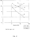
- an atmospheric pressure glow discharge plasma was generated by applying air with a velocity of 2 m/s into the discharge space at an amplitude of the applied voltage of 4.5 kV. Both electrodes are covered with a dielectric material comprising of polyethylenenaphtalate (PEN) and having a thickness of 100 ⁇ m. The gap distance between the electrodes (typically forming the discharge space) is 1 mm.
- An LC matching network is incorporated in the plasma arrangement. The results of the measurements are listed in the table below and are presented in figure 5 . Again the power P coupled into the APG plasma 31, the exposure non-uniformity parameter ⁇ D 32 and the minimum time of exposure t minim 33 are shown. f [kHz] P [W] ⁇ D [%] t minim [s] 129 46 290 63 30 52 120 135 70 89 70 5 282 290 20 9
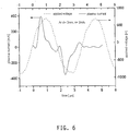
- figure 6 presents a diagram of the AC-voltage applied to the electrodes and the plasma current of a plasma generated using a method or arrangement according to the present invention.
- the carrier gas used was argon at a flow velocity of 2 m/s, the gap distance was 2 mm.
- the plasma current is shown by the solid line and the applied voltage by the dotted line.
- the rise time of the applied voltage will also increase and also the duration of the transitional state during which the voltage applied to the plasma increases before being lowered by the field of the charge accumulated on the dielectric.
- the maximum allowed plasma current with a DBD system increases proportional with the frequency, so that at higher frequencies the current can be very high increasing the probability of the glow to an (unfavourable) arc transition.
Landscapes
- Chemical & Material Sciences (AREA)
- Engineering & Computer Science (AREA)
- Physics & Mathematics (AREA)
- Plasma & Fusion (AREA)
- Analytical Chemistry (AREA)
- Materials Engineering (AREA)
- Chemical Kinetics & Catalysis (AREA)
- Mechanical Engineering (AREA)
- Metallurgy (AREA)
- Organic Chemistry (AREA)
- General Chemical & Material Sciences (AREA)
- Power Engineering (AREA)
- Spectroscopy & Molecular Physics (AREA)
- Treatments Of Macromolecular Shaped Articles (AREA)
- Physical Or Chemical Processes And Apparatus (AREA)
Claims (40)
- Procédé de traitement d'un substrat (3) en utilisant un plasma à décharge luminescente sous pression atmosphérique (APG) (7), dans lequel une pluralité d'électrodes (4,5) sont agencées définissant un espace de décharge (10) pour former ledit plasma (7), dans lequel lesdites électrodes (4, 5) sont reliées à une alimentation électrique (8) et une tension alternative est appliquée, par ladite alimentation électrique (8), auxdites électrodes (4, 5), et dans lequel une substance gazeuse (6) est prévue dans ledit espace de décharge (10), dans lequel ladite tension alternative appliquée auxdites électrodes (4, 5) a une amplitude égale à au moins la tension de claquage de ladite substance gazeuse (6) et a une fréquence d'au moins 100 kHz, dans lequel ladite substance gazeuse (6) comprend essentiellement au moins l'un d'un groupe comprenant de l'argon, de l'azote et de l'air, et dans lequel au moins un autre gaz est fourni à ladite substance gazeuse (6) dans ledit espace de décharge (10), et dans lequel ledit substrat (3) est exposé audit plasma (7), caractérisé en ce que ledit procédé comprend une étape de réglage de ladite amplitude de tension alternative pendant la décharge, afin de maintenir un plasma à décharge luminescente, à une tension supérieure ou égale à ladite tension de claquage pour réduire la température appliquée audit substrat (3) pour éviter l'endommagement thermique dudit substrat (3), dans lequel ladite amplitude de tension alternative est inférieure ou égale à 140% de ladite tension de claquage, dans lequel ladite étape de fourniture dudit autre gaz comprend les étapes consistant :à fournir ledit autre gaz audit espace de décharge (10) après avoir essentiellement stabilisé ledit plasma (7) de sorte que la concentration dudit autre gaz augmente progressivement par paliers ; età stabiliser ledit plasma (7) en ajustant ladite amplitude de tension alternative après chaque incrément progressif de ladite concentration dudit autre gaz.
- Procédé selon la revendication 1, dans lequel ladite amplitude de tension alternative est comprise entre 110% et 120% de ladite tension de claquage.
- Procédé selon l'une des revendications précédentes, dans lequel, au cours dudit procédé, la température de ladite substance gazeuse (6) est maintenue inférieure à 100°C.
- Procédé selon l'une des revendications précédentes, dans lequel ledit au moins un autre gaz est fourni à ladite substance gazeuse (6) dans une concentration d'au plus 50% par volume.
- Procédé selon la revendication 4, dans lequel ladite concentration est d'au plus 20% par volume.
- Procédé selon l'une des revendications 4 et 5, dans lequel ledit au moins un autre gaz fourni à ladite substance gazeuse (6) dans ledit espace de décharge (10) est constitué d'au moins l'un d'un groupe comprenant O2, CO2, NH3, des hydrocarbures, des organosiliciums tels que TEOS et HMDSO, des composés organométalliques, ou SiH4, et des combinaisons de ceux-ci.
- Procédé selon l'une des revendications précédentes, dans lequel ladite substance gazeuse (6) fournie dans ledit espace de décharge (10) s'écoule à travers ledit espace de décharge (10), établissant un écoulement gazeux (6).
- Procédé selon la revendication 7, dans lequel ledit écoulement gazeux (6) a un débit se trouvant dans une plage allant de 1 l/min à 50 l/min.
- Procédé selon l'une des revendications 7 et 8, dans lequel la vitesse de l'écoulement gazeux (6) se trouve dans la plage allant de 0,1 à 10 m/s.
- Procédé selon la revendication 9, dans lequel la vitesse de l'écoulement gazeux (6) se trouve dans la plage allant de 1 à 5 m/s.
- Procédé selon l'une des revendications précédentes, dans lequel ladite tension alternative est choisie de manière à avoir une fréquence inférieure à 1 MHz.
- Procédé selon la revendication 11, dans lequel ladite fréquence de la tension alternative est choisie dans une plage allant de 100 kHz à 700 kHz.
- Procédé selon l'une des revendications précédentes utilisé pour traiter un film de polymère thermoplastique, dans lequel un temps de séjour dudit film de polymère thermoplastique dans ledit espace de décharge (10) est choisi de sorte que ledit film de polymère thermoplastique soit maintenu à une température inférieure à ladite température de transition vitreuse dudit film de polymère thermoplastique.
- Procédé selon la revendication 13, dans lequel ledit temps de séjour est réglé en déplaçant ledit film à travers ledit espace de décharge (10) et en réglant la vitesse dudit film.
- Procédé selon l'une des revendications précédentes utilisé pour traiter un film de polymère thermoplastique, dans lequel l'amplitude de ladite tension alternative est choisie de sorte que la température de l'espace de décharge (10) reste inférieure à une température de transition vitreuse dudit film de polymère thermoplastique pendant le traitement dudit film et pour maintenir ledit plasma luminescent (7).
- Procédé selon l'une des revendications 13 à 15, dans lequel ledit film de polymère thermoplastique comprend au moins l'un d'un groupe comprenant la triacétylcellulose (TAC), le polyéthylènetéréphthalate (PET) et le polyéthylènenaphtalate (PEN).
- Procédé selon l'une des revendications précédentes, dans lequel au moins l'une desdites électrodes (4, 5) est recouverte d'un film de matériau diélectrique (2).
- Procédé selon la revendication 17, dans lequel ledit film de matériau diélectrique (2) est choisi de manière à avoir une épaisseur se trouvant dans une plage allant de 1 µm à 1000 µm.
- Procédé selon la revendication 18, dans lequel ladite épaisseur est comprise dans une plage allant de 250 µm à 500 µm.
- Procédé selon l'une des revendications précédentes, dans lequel au moins deux desdites électrodes (4, 5) sont espacées l'une de l'autre sur une distance comprise dans une plage allant de 100 µm à 5000 µm.
- Procédé selon la revendication 20, dans lequel ladite distance est choisie dans une plage allant de 250 µm à 1500 µm.
- Procédé selon l'une des revendications précédentes, dans lequel un temps de montée de tension définit l'intervalle de temps le plus court pour que ladite tension alternative atteigne sa valeur maximale à partir de zéro, et dans lequel ledit temps de montée de tension de la tension alternative se trouve dans la plage allant de 0,1 à 10 kV/µs.
- Procédé selon l'une des revendications précédentes, dans lequel la densité de courant à travers ledit plasma (7) est maintenue en dessous de 10 mA/cm2.
- Procédé selon l'une des revendications précédentes, utilisé pour traiter un substrat (3) dans ledit espace de décharge (10) avec un procédé de dépôt chimique en phase vapeur en utilisant ledit plasma (7).
- Agencement pour traiter un substrat (3) en utilisant un plasma à décharge luminescente sous pression atmosphérique (APG) (7), comprenant une pluralité d'électrodes (4,5) agencées de sorte qu'un espace de décharge (10) soit défini par lesdites électrodes (4, 5), comprenant en outre une alimentation électrique (8) pour appliquer une tension alternative auxdites électrodes (4, 5) pour générer ledit plasma (7), et des moyens (19, 21-24, 34) pour fournir une substance gazeuse (6) audit espace de décharge (10), dans lequel lesdits moyens (19, 21-24, 34) comprennent un moyen de stockage de gaz comprenant ladite substance gazeuse (6), dans lequel ladite alimentation électrique (8) pour appliquer la tension alternative auxdites électrodes (4, 5) est agencée pour appliquer la tension alternative ayant une amplitude égale à au moins une tension de claquage de ladite substance gazeuse (6) et ayant une fréquence d'au moins 100 kHz, la substance gazeuse (6) comprenant au moins l'un d'un groupe comprenant de l'argon, de l'azote et de l'air, et comprenant en outre au moins un autre gaz, caractérisé en ce que ladite alimentation électrique (8) pour appliquer la tension alternative auxdites électrodes (4,5) est agencée pour régler ladite amplitude de tension alternative pendant la décharge, afin de maintenir un plasma à décharge luminescente, à une tension supérieure ou égale à ladite tension de claquage pour réduire la température appliquée audit substrat (3) pour éviter un endommagement thermique dudit substrat (3), dans lequel l'amplitude de tension alternative va jusqu'à 140% de ladite tension de claquage, et dans lequel lesdits moyens (19, 21-24, 34) pour fournir la substance gazeuse (6) sont agencés pourfournir ledit au moins un autre gaz audit espace de décharge (10) après avoir essentiellement stabilisé ledit plasma (7) de sorte que la concentration dudit autre gaz augmente progressivement par paliers ; et dans lequel ladite alimentation électrique (8) est agencée pourstabiliser ledit plasma (7) en ajustant ladite amplitude de tension alternative après chaque incrément progressif de ladite concentration dudit autre gaz.
- Agencement selon la revendication 25, dans lequel ledit au moins un autre gaz comprend l'un d'un groupe comprenant O2, CO2, NH3, des hydrocarbures, des organosiliciums tels que TEOS et HMDSO, des composés organométalliques, ou SiH4, et des combinaisons de ceux-ci.
- Agencement selon l'une des revendications 25 et 26, comprenant un moyen (17) pour amener ladite substance gazeuse (6) à s'écouler à travers ledit espace de décharge (10).
- Agencement selon la revendication 27, dans lequel ledit moyen (17) pour amener ladite substance gazeuse (6) à s'écouler à travers ledit espace de décharge (10) est agencé pour établir un écoulement avec un débit se trouvant dans une plage allant de 1 l/min à 50 l/min.
- Agencement selon la revendication 28, dans lequel ledit moyen (17) pour amener ladite substance gazeuse (6) à s'écouler à travers ledit espace de décharge (10) est agencé pour établir un écoulement avec une vitesse d'écoulement se trouvant dans une plage allant de de 0,1 à 10 m/s.
- Agencement selon l'une des revendications 25 à 29, dans lequel ledit moyen (8) pour appliquer une tension alternative haute fréquence est agencé pour appliquer une tension comprenant une fréquence se trouvant dans une plage allant de 100 kHz à 1 MHz.
- Agencement selon l'une des revendications 25 à 30, dans lequel au moins l'une desdites électrodes (4, 5) est agencée pour supporter un film de polymère thermoplastique à traiter par ledit plasma (7).
- Agencement selon la revendication 31, comprenant en outre un moyen agencé pour déplacer ledit film de polymère thermoplastique à travers ledit espace de décharge (10) avec une vitesse pour laquelle le temps de séjour dudit film est tel que le film est maintenu à une température inférieure à ladite température de transition vitreuse dudit film de polymère thermoplastique.
- Agencement selon l'une des revendications 31 ou 32, dans lequel ledit moyen (8) pour appliquer une tension alternative est agencé pour fournir une tension alternative ayant une amplitude telle que la température de l'espace de décharge (10) reste inférieure à une température de transition vitreuse dudit film de polymère thermoplastique pendant le traitement dudit film.
- Agencement selon l'une des revendications 25 à 33, comprenant un film de matériau diélectrique (2) contigu à au moins l'une desdites électrodes (4, 5).
- Agencement selon la revendication 34, dans lequel ledit film de matériau diélectrique (2) a une épaisseur se trouvant dans une plage allant de 1 µm à 1000 µm.
- Agencement selon l'une des revendications 25 à 35, dans lequel un espacement entre lesdites électrodes (4, 5) se trouve dans une plage allant de 0,1 mm à 5 mm.
- Agencement selon l'une des revendications 25 à 36, agencé pour ajuster l'intervalle de temps le plus court pour que ladite tension alternative atteigne sa valeur maximale à partir de zéro, et dans lequel ledit ajustement peut être effectué au moins dans une plage allant de 0,1 à 10 kV/µs.
- Agencement selon l'une des revendications 25 à 37, agencé pour ajuster la fréquence de ladite tension alternative pour maintenir la densité de courant à travers ledit plasma (7) dans une plage inférieure à 10 mA/cm2.
- Agencement selon l'une des revendications 25 à 38, comprenant une bobine d'arrêt de courant agencée pour régler la tension pendant le claquage.
- Agencement selon l'une des revendications 25 à 39, ledit agencement étant agencé pour effectuer un procédé de traitement par dépôt chimique en phase vapeur sur un substrat (3) dans ledit espace de décharge (10) en utilisant ledit plasma (7).
Priority Applications (1)
| Application Number | Priority Date | Filing Date | Title |
|---|---|---|---|
| EP03798190.9A EP1547123B1 (fr) | 2002-09-30 | 2003-09-30 | Procede et dispositif de traitement d'un substrat au moyen d'un plasma a decharge luminescente a pression atmospherique |
Applications Claiming Priority (4)
| Application Number | Priority Date | Filing Date | Title |
|---|---|---|---|
| EP02079074 | 2002-09-30 | ||
| EP20020079074 EP1403902A1 (fr) | 2002-09-30 | 2002-09-30 | Procédé et dispositif de production d'un plasma de décharge luminescente sous pression atmosphérique |
| EP03798190.9A EP1547123B1 (fr) | 2002-09-30 | 2003-09-30 | Procede et dispositif de traitement d'un substrat au moyen d'un plasma a decharge luminescente a pression atmospherique |
| PCT/EP2003/010923 WO2004030019A1 (fr) | 2002-09-30 | 2003-09-30 | Procede et dispositif destines a produire un plasma a decharge luminescente a pression atmospherique (apg) |
Publications (2)
| Publication Number | Publication Date |
|---|---|
| EP1547123A1 EP1547123A1 (fr) | 2005-06-29 |
| EP1547123B1 true EP1547123B1 (fr) | 2018-08-29 |
Family
ID=31970433
Family Applications (2)
| Application Number | Title | Priority Date | Filing Date |
|---|---|---|---|
| EP20020079074 Withdrawn EP1403902A1 (fr) | 2002-09-30 | 2002-09-30 | Procédé et dispositif de production d'un plasma de décharge luminescente sous pression atmosphérique |
| EP03798190.9A Expired - Lifetime EP1547123B1 (fr) | 2002-09-30 | 2003-09-30 | Procede et dispositif de traitement d'un substrat au moyen d'un plasma a decharge luminescente a pression atmospherique |
Family Applications Before (1)
| Application Number | Title | Priority Date | Filing Date |
|---|---|---|---|
| EP20020079074 Withdrawn EP1403902A1 (fr) | 2002-09-30 | 2002-09-30 | Procédé et dispositif de production d'un plasma de décharge luminescente sous pression atmosphérique |
Country Status (5)
| Country | Link |
|---|---|
| US (1) | US7491429B2 (fr) |
| EP (2) | EP1403902A1 (fr) |
| JP (1) | JP4921710B2 (fr) |
| AU (1) | AU2003276023A1 (fr) |
| WO (1) | WO2004030019A1 (fr) |
Families Citing this family (32)
| Publication number | Priority date | Publication date | Assignee | Title |
|---|---|---|---|---|
| DE602004003697T2 (de) | 2004-08-13 | 2007-10-04 | Fuji Film Manufacturing Europe B.V. | Verfahren und Vorrichtung zur Steuerung eines Glühentladungsplasmas unter atmosphärischem Druck |
| DE102004048410A1 (de) * | 2004-10-01 | 2006-05-04 | Institut für Niedertemperatur-Plasmaphysik e.V. | Anordnung zur Oberflächenbehandlung von Schüttgut in einer Plasmazone bei Atmosphärendruck |
| WO2007024134A1 (fr) * | 2005-08-26 | 2007-03-01 | Fujifilm Manufacturing Europe B.V. | Procede et installation pour la production et le controle de plasma de decharge |
| JP4782529B2 (ja) * | 2005-10-06 | 2011-09-28 | エア・ウォーター株式会社 | 表示装置の製造方法 |
| US20080274298A1 (en) * | 2005-12-23 | 2008-11-06 | Francesco Parisi | Plant for the Plasma Surface Treatment of an Alveolar Sheet of Plastic Material |
| JP2009538989A (ja) | 2006-05-30 | 2009-11-12 | フジフィルム マニュファクチャリング ユーロプ ビー.ブイ. | パルス化大気圧グロー放電を使用する堆積の方法及び装置 |
| US20090324971A1 (en) * | 2006-06-16 | 2009-12-31 | Fujifilm Manufacturing Europe B.V. | Method and apparatus for atomic layer deposition using an atmospheric pressure glow discharge plasma |
| WO2008045226A1 (fr) * | 2006-10-06 | 2008-04-17 | Dow Global Technologies Inc. | Procédé de revêtement par dépôt chimique en phase vapeur activé par plasma |
| US20080179286A1 (en) * | 2007-01-29 | 2008-07-31 | Igor Murokh | Dielectric plasma chamber apparatus and method with exterior electrodes |
| US8338307B2 (en) | 2007-02-13 | 2012-12-25 | Fujifilm Manufacturing Europe B.V. | Substrate plasma treatment using magnetic mask device |
| US20100255625A1 (en) * | 2007-09-07 | 2010-10-07 | Fujifilm Manufacturing Europe B.V. | Method and apparatus for atomic layer deposition using an atmospheric pressure glow discharge plasma |
| JP4947807B2 (ja) * | 2007-09-09 | 2012-06-06 | 一男 清水 | プラズマを用いた流体浄化方法および流体浄化装置 |
| WO2009096785A1 (fr) * | 2008-02-01 | 2009-08-06 | Fujifilm Manufacturing Europe B.V. | Procédé et appareil de traitement de surface par plasma sur un substrat mouvant |
| ATE523067T1 (de) | 2008-02-08 | 2011-09-15 | Fujifilm Mfg Europe Bv | Verfahren zur herstellung einer mehrschichtigen stapelstruktur mit verbesserter wvtr- grenzeigenschaft |
| US20110014424A1 (en) | 2008-02-21 | 2011-01-20 | Fujifilm Manufacturing Europe B.V. | Plasma treatment apparatus and method for treatment of a substrate with atmospheric pressure glow discharge electrode configuration |
| US8609203B2 (en) | 2008-06-06 | 2013-12-17 | Fujifilm Manufacturing Europe B.V. | Method and apparatus for plasma surface treatment of moving substrate |
| EP2180768A1 (fr) * | 2008-10-23 | 2010-04-28 | TNO Nederlandse Organisatie voor Toegepast Wetenschappelijk Onderzoek | Appareil et procédé pour traiter un objet |
| EP2205049A1 (fr) * | 2008-12-30 | 2010-07-07 | Nederlandse Organisatie voor toegepast-natuurwetenschappelijk Onderzoek TNO | Appareil et procédé pour traiter un objet |
| GB2466664B (en) * | 2009-01-06 | 2015-04-01 | Perlemax Ltd | Plasma microreactor apparatus, sterilisation unit and analyser |
| EP2396451B1 (fr) | 2009-02-12 | 2012-11-07 | Fujifilm Manufacturing Europe BV | Barrière à deux couches sur un substrat polymère |
| EP2226832A1 (fr) | 2009-03-06 | 2010-09-08 | FUJIFILM Manufacturing Europe B.V. | Traitement de substrat au plasma utilisant des languettes latérales |
| GB0910040D0 (en) * | 2009-06-11 | 2009-07-22 | Fujifilm Mfg Europe Bv | Substrate structure |
| GB201110117D0 (en) * | 2011-06-16 | 2011-07-27 | Fujifilm Mfg Europe Bv | method and device for manufacturing a barrie layer on a flexible substrate |
| GB201117242D0 (en) | 2011-10-06 | 2011-11-16 | Fujifilm Mfg Europe Bv | Method and device for manufacturing a barrier layer on a flexible subtrate |
| NL2007705C2 (en) | 2011-11-02 | 2013-05-21 | Stichting Energie | Low cost polymer supported hybrid silica membrane and production thereof. |
| WO2013090418A1 (fr) | 2011-12-12 | 2013-06-20 | Applied Quantum Energy Llc | Stérilisation à l'aide de nox produit par plasma |
| KR101391708B1 (ko) * | 2012-06-07 | 2014-05-07 | 한국식품연구원 | 대기압 플라즈마를 이용한 밀봉 포장식품의 살균방법 및 이에 의해 제조된 밀봉 포장식품 |
| GB201210836D0 (en) | 2012-06-19 | 2012-08-01 | Fujifilm Mfg Europe Bv | Method and device for manufacturing a barrier layer on a flexible substrate |
| US9498637B2 (en) * | 2014-05-30 | 2016-11-22 | Plasmology4, Inc. | Wearable cold plasma system |
| JP2023528038A (ja) * | 2020-06-02 | 2023-07-03 | ザ、トラスティーズ オブ プリンストン ユニバーシティ | 低温布製誘電体バリア放電デバイス |
| CN113141700B (zh) * | 2021-03-16 | 2022-07-12 | 深圳大学 | 大气压空气均匀介质阻挡放电的电极结构和方法 |
| JP7832461B2 (ja) * | 2022-02-07 | 2026-03-18 | 日新電機株式会社 | プラズマ処理装置 |
Citations (1)
| Publication number | Priority date | Publication date | Assignee | Title |
|---|---|---|---|---|
| EP1383359A2 (fr) * | 2002-07-19 | 2004-01-21 | Fuji Photo Film B.V. | Procédé et dispositif de traitement d'un substrat par décharge luminescente sous pression atmosphérique |
Family Cites Families (19)
| Publication number | Priority date | Publication date | Assignee | Title |
|---|---|---|---|---|
| JP3142660B2 (ja) * | 1991-09-02 | 2001-03-07 | 株式会社きもと | グロー放電プラズマ発生用電極及びこの電極を用いた反応装置 |
| US5414324A (en) * | 1993-05-28 | 1995-05-09 | The University Of Tennessee Research Corporation | One atmosphere, uniform glow discharge plasma |
| US5403453A (en) * | 1993-05-28 | 1995-04-04 | The University Of Tennessee Research Corporation | Method and apparatus for glow discharge plasma treatment of polymer materials at atmospheric pressure |
| US5585147A (en) * | 1994-06-28 | 1996-12-17 | Matsushita Electric Works, Ltd. | Process for a surface treatment of a glass fabric |
| JP3136951B2 (ja) * | 1994-06-28 | 2001-02-19 | 松下電工株式会社 | ガラスクロスの表面処理方法 |
| US5558843A (en) * | 1994-09-01 | 1996-09-24 | Eastman Kodak Company | Near atmospheric pressure treatment of polymers using helium discharges |
| US5714308A (en) | 1996-02-13 | 1998-02-03 | Eastman Kodak Company | Atmospheric pressure glow discharge treatment of polymeric supports to promote adhesion for photographic applications |
| CA2205817C (fr) * | 1996-05-24 | 2004-04-06 | Sekisui Chemical Co., Ltd. | Traitement a decharge luminescente du plasma et appareil utilise a cette fin |
| US5789145A (en) * | 1996-07-23 | 1998-08-04 | Eastman Kodak Company | Atmospheric pressure glow discharge treatment of base material for photographic applications |
| JP3646282B2 (ja) * | 1997-04-24 | 2005-05-11 | コニカミノルタホールディングス株式会社 | 支持体の表面処理装置 |
| JP3380846B2 (ja) * | 1997-11-05 | 2003-02-24 | 松下電器産業株式会社 | 半導体装置の製造方法 |
| FR2782837B1 (fr) * | 1998-08-28 | 2000-09-29 | Air Liquide | Procede et dispositif de traitement de surface par plasma a pression atmospherique |
| NL1010287C2 (nl) * | 1998-10-09 | 2000-04-11 | Fuji Photo Film Bv | Werkwijze voor de behandeling van een fotografische drager met een atmosferische druk gloeiontlading. |
| US6441553B1 (en) * | 1999-02-01 | 2002-08-27 | Sigma Technologies International, Inc. | Electrode for glow-discharge atmospheric-pressure plasma treatment |
| JP2001158415A (ja) * | 1999-12-02 | 2001-06-12 | Showa Denko Kk | 大気圧低温プラズマ処理プラスチックボトル及びその製造方法 |
| JP3559513B2 (ja) * | 2000-09-05 | 2004-09-02 | 株式会社東芝 | 磁気抵抗効果素子、その製造方法及び製造装置並びに磁気再生装置 |
| JP3776720B2 (ja) * | 2000-12-06 | 2006-05-17 | 三菱重工業株式会社 | 印刷版の再生方法及び印刷機 |
| JP3576094B2 (ja) * | 2000-12-07 | 2004-10-13 | シャープ株式会社 | 薄膜製造方法 |
| JP4254236B2 (ja) * | 2000-12-12 | 2009-04-15 | コニカミノルタホールディングス株式会社 | 薄膜形成方法 |
-
2002
- 2002-09-30 EP EP20020079074 patent/EP1403902A1/fr not_active Withdrawn
-
2003
- 2003-09-30 AU AU2003276023A patent/AU2003276023A1/en not_active Abandoned
- 2003-09-30 JP JP2004539055A patent/JP4921710B2/ja not_active Expired - Fee Related
- 2003-09-30 WO PCT/EP2003/010923 patent/WO2004030019A1/fr not_active Ceased
- 2003-09-30 EP EP03798190.9A patent/EP1547123B1/fr not_active Expired - Lifetime
- 2003-09-30 US US10/529,786 patent/US7491429B2/en not_active Expired - Fee Related
Patent Citations (1)
| Publication number | Priority date | Publication date | Assignee | Title |
|---|---|---|---|---|
| EP1383359A2 (fr) * | 2002-07-19 | 2004-01-21 | Fuji Photo Film B.V. | Procédé et dispositif de traitement d'un substrat par décharge luminescente sous pression atmosphérique |
Also Published As
| Publication number | Publication date |
|---|---|
| JP4921710B2 (ja) | 2012-04-25 |
| US7491429B2 (en) | 2009-02-17 |
| US20060147648A1 (en) | 2006-07-06 |
| WO2004030019A1 (fr) | 2004-04-08 |
| JP2006503406A (ja) | 2006-01-26 |
| EP1547123A1 (fr) | 2005-06-29 |
| EP1403902A1 (fr) | 2004-03-31 |
| AU2003276023A1 (en) | 2004-04-19 |
Similar Documents
| Publication | Publication Date | Title |
|---|---|---|
| EP1547123B1 (fr) | Procede et dispositif de traitement d'un substrat au moyen d'un plasma a decharge luminescente a pression atmospherique | |
| US6299948B1 (en) | Method and device for surface treatment with a plasma at atmospheric pressure | |
| US7288204B2 (en) | Method and arrangement for treating a substrate with an atmospheric pressure glow plasma (APG) | |
| Guimond et al. | Surface degradation and hydrophobic recovery of polyolefins treated by air corona and nitrogen atmospheric pressure glow discharge | |
| JP3405808B2 (ja) | 酸化珪素の沈着物の形成方法及びこれに使用する装置 | |
| US7615931B2 (en) | Pulsed dielectric barrier discharge | |
| US7281491B2 (en) | Dielectric-coated electrode, plasma discharge treatment apparatus and method for forming thin film | |
| Kogelschatz et al. | Fundamentals and applications of dielectric-barrier discharges | |
| Borcia et al. | Using a He+ N2 dielectric barrier discharge for the modification of polymer surface properties | |
| JP2004509432A (ja) | グロー放電プラズマ処理装置及びグロー放電プラズマ処理方法 | |
| Starostin et al. | On the formation mechanisms of the diffuse atmospheric pressure dielectric barrier discharge in CVD processes of thin silica-like films | |
| CA2120460A1 (fr) | Polymerisation du plasma et modification de la surface a l'interieur de microsubstrats creux | |
| Siliprandi et al. | Atmospheric pressure plasma discharge for polysiloxane thin films deposition and comparison with low pressure process | |
| Somekawa et al. | Effects of self-erasing discharges on the uniformity of the dielectric barrier discharge | |
| EP1548795A1 (fr) | Verfahren und Vorrichtung zur Stabilisierung eines Glimmentladungsplasma unter atmosphärischen Bedingungen | |
| CA2295729A1 (fr) | Systemes de traitement par plasma et procedes de traitement par plasma | |
| Abou Rich et al. | LDPE surface modifications induced by atmospheric plasma torches with linear and showerhead configurations | |
| US20030049468A1 (en) | Cascade arc plasma and abrasion resistant coatings made therefrom | |
| US20040115872A1 (en) | Method and device for generating an activated gas curtain for surface treatment | |
| Setiawan et al. | Atmospheric pressure plasma jet for surface material modification: a mini-review | |
| WO2002094455A1 (fr) | Procede et appareil de traitement au plasma | |
| Mishra et al. | Novel approach to produce polymerized hydrocarbon coatings using dielectric barrier controlled atmospheric pressure glow discharge plasma | |
| Sarani et al. | Characterization of an atmospheric pressure plasma jet and its application for treatment of non-woven textiles | |
| Choi et al. | Analysis of polymer surface treated by dielectric barrier discharge | |
| JP2001049443A (ja) | 放電プラズマを利用したSiO2薄膜形成方法 |
Legal Events
| Date | Code | Title | Description |
|---|---|---|---|
| PUAI | Public reference made under article 153(3) epc to a published international application that has entered the european phase |
Free format text: ORIGINAL CODE: 0009012 |
|
| 17P | Request for examination filed |
Effective date: 20050316 |
|
| AK | Designated contracting states |
Kind code of ref document: A1 Designated state(s): AT BE BG CH CY CZ DE DK EE ES FI FR GB GR HU IE IT LI LU MC NL PT RO SE SI SK TR |
|
| AX | Request for extension of the european patent |
Extension state: AL LT LV MK |
|
| DAX | Request for extension of the european patent (deleted) | ||
| RBV | Designated contracting states (corrected) |
Designated state(s): DE FR GB NL |
|
| RAP1 | Party data changed (applicant data changed or rights of an application transferred) |
Owner name: FUJI FILM MANUFACTURING EUROPE B.V. |
|
| RAP1 | Party data changed (applicant data changed or rights of an application transferred) |
Owner name: FUJIFILM MANUFACTURING EUROPE B.V. |
|
| 17Q | First examination report despatched |
Effective date: 20100507 |
|
| GRAP | Despatch of communication of intention to grant a patent |
Free format text: ORIGINAL CODE: EPIDOSNIGR1 |
|
| RIC1 | Information provided on ipc code assigned before grant |
Ipc: B05D 3/14 19740701ALI20180302BHEP Ipc: H01J 37/32 19680901AFI20180302BHEP Ipc: C23C 16/50 19850101ALI20180302BHEP Ipc: H05H 1/24 19740701ALI20180302BHEP |
|
| INTG | Intention to grant announced |
Effective date: 20180403 |
|
| RIN1 | Information on inventor provided before grant (corrected) |
Inventor name: VAN DE SANDEN, MAURITIUS, CORNELIUS, MARIA Inventor name: DE VRIES, HINDRIK, WILLEM Inventor name: ALDEA, EUGEN Inventor name: MORI, FUYUHIKO |
|
| GRAS | Grant fee paid |
Free format text: ORIGINAL CODE: EPIDOSNIGR3 |
|
| GRAA | (expected) grant |
Free format text: ORIGINAL CODE: 0009210 |
|
| AK | Designated contracting states |
Kind code of ref document: B1 Designated state(s): DE FR GB NL |
|
| REG | Reference to a national code |
Ref country code: GB Ref legal event code: FG4D |
|
| REG | Reference to a national code |
Ref country code: FR Ref legal event code: PLFP Year of fee payment: 16 |
|
| REG | Reference to a national code |
Ref country code: DE Ref legal event code: R096 Ref document number: 60351437 Country of ref document: DE |
|
| REG | Reference to a national code |
Ref country code: NL Ref legal event code: FP |
|
| RIC2 | Information provided on ipc code assigned after grant |
Ipc: C23C 16/50 20060101ALI20180302BHEP Ipc: H01J 37/32 20060101AFI20180302BHEP Ipc: B05D 3/14 20060101ALI20180302BHEP Ipc: H05H 1/24 20060101ALI20180302BHEP |
|
| REG | Reference to a national code |
Ref country code: DE Ref legal event code: R097 Ref document number: 60351437 Country of ref document: DE |
|
| PLBE | No opposition filed within time limit |
Free format text: ORIGINAL CODE: 0009261 |
|
| STAA | Information on the status of an ep patent application or granted ep patent |
Free format text: STATUS: NO OPPOSITION FILED WITHIN TIME LIMIT |
|
| 26N | No opposition filed |
Effective date: 20190531 |
|
| PGFP | Annual fee paid to national office [announced via postgrant information from national office to epo] |
Ref country code: FR Payment date: 20190925 Year of fee payment: 17 Ref country code: NL Payment date: 20190926 Year of fee payment: 17 |
|
| PGFP | Annual fee paid to national office [announced via postgrant information from national office to epo] |
Ref country code: GB Payment date: 20190927 Year of fee payment: 17 |
|
| PGFP | Annual fee paid to national office [announced via postgrant information from national office to epo] |
Ref country code: DE Payment date: 20190927 Year of fee payment: 17 |
|
| REG | Reference to a national code |
Ref country code: DE Ref legal event code: R119 Ref document number: 60351437 Country of ref document: DE |
|
| REG | Reference to a national code |
Ref country code: NL Ref legal event code: MM Effective date: 20201001 |
|
| GBPC | Gb: european patent ceased through non-payment of renewal fee |
Effective date: 20200930 |
|
| PG25 | Lapsed in a contracting state [announced via postgrant information from national office to epo] |
Ref country code: NL Free format text: LAPSE BECAUSE OF NON-PAYMENT OF DUE FEES Effective date: 20201001 |
|
| PG25 | Lapsed in a contracting state [announced via postgrant information from national office to epo] |
Ref country code: DE Free format text: LAPSE BECAUSE OF NON-PAYMENT OF DUE FEES Effective date: 20210401 Ref country code: FR Free format text: LAPSE BECAUSE OF NON-PAYMENT OF DUE FEES Effective date: 20200930 |
|
| PG25 | Lapsed in a contracting state [announced via postgrant information from national office to epo] |
Ref country code: GB Free format text: LAPSE BECAUSE OF NON-PAYMENT OF DUE FEES Effective date: 20200930 |