EP1552972A2 - Air flap driving device - Google Patents
Air flap driving device Download PDFInfo
- Publication number
- EP1552972A2 EP1552972A2 EP05000108A EP05000108A EP1552972A2 EP 1552972 A2 EP1552972 A2 EP 1552972A2 EP 05000108 A EP05000108 A EP 05000108A EP 05000108 A EP05000108 A EP 05000108A EP 1552972 A2 EP1552972 A2 EP 1552972A2
- Authority
- EP
- European Patent Office
- Prior art keywords
- damping
- damping element
- drive device
- output shaft
- air damper
- Prior art date
- Legal status (The legal status is an assumption and is not a legal conclusion. Google has not performed a legal analysis and makes no representation as to the accuracy of the status listed.)
- Granted
Links
Images

Classifications
-
- B—PERFORMING OPERATIONS; TRANSPORTING
- B60—VEHICLES IN GENERAL
- B60H—ARRANGEMENTS OF HEATING, COOLING, VENTILATING OR OTHER AIR-TREATING DEVICES SPECIALLY ADAPTED FOR PASSENGER OR GOODS SPACES OF VEHICLES
- B60H1/00—Heating, cooling or ventilating devices
- B60H1/00642—Control systems or circuits; Control members or indication devices for heating, cooling or ventilating devices
- B60H1/00814—Control systems or circuits characterised by their output, for controlling particular components of the heating, cooling or ventilating installation
- B60H1/00821—Control systems or circuits characterised by their output, for controlling particular components of the heating, cooling or ventilating installation the components being ventilating, air admitting or air distributing devices
- B60H1/00835—Damper doors, e.g. position control
- B60H1/00857—Damper doors, e.g. position control characterised by the means connecting the initiating means, e.g. control lever, to the damper door
-
- B—PERFORMING OPERATIONS; TRANSPORTING
- B60—VEHICLES IN GENERAL
- B60H—ARRANGEMENTS OF HEATING, COOLING, VENTILATING OR OTHER AIR-TREATING DEVICES SPECIALLY ADAPTED FOR PASSENGER OR GOODS SPACES OF VEHICLES
- B60H1/00—Heating, cooling or ventilating devices
- B60H1/00642—Control systems or circuits; Control members or indication devices for heating, cooling or ventilating devices
- B60H1/00664—Construction or arrangement of damper doors
Definitions
- the invention relates to a damper drive device for pivoting an air damper of a ventilation system, in particular a motor vehicle ventilation system, about a pivot axis, with an electric motor for pivoting the air damper drives an output shaft.
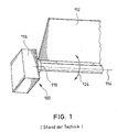
- FIG. 1 shows an example of the generic air flap drive devices, as they currently, for example, to regulate the fresh air or Recirculating air quantity can be used in automotive ventilation systems.
- the damper drive device comprises 100 an electric motor 116 with an internal (not shown) transmission, for pivoting an air damper 112 about a pivot axis 114 drives an output shaft 118.
- the electric motor 116 or the internal transmission associated therewith In terms of its strength, it is only able to force up to one certain size.
- the engine hub or the output shaft 118 directly to the fulcrum or the pivot axis 114 of the damper 112, wherein it is in this Air damper 112 is an off-center mounted "angle flap", that is the pivot point or the pivot axis 114 is not in the center of gravity the air damper 112.
- the invention is based on the object, the generic air damper drive devices to improve such that the above-explained Problems are eliminated or at least reduced.
- the air damper drive device is based on the generic State of the art in that a damping device for Damping is provided by applied to the damper torque.
- a damping device for Damping is provided by applied to the damper torque.
- inventively provided damping device are the on the air damper or the electric motor exerted large Torques so dampened that damage to the electric motor and or a possibly assigned thereto internal transmission avoided becomes.
- This solution is, but is not limited to, especially one direct connection of engine hub or output shaft and air damper advantageous. This applies even more if the air damper is stored off-center is, that is, if the pivot axis of the damper does not through their Focus extends.
- the damping device is a coupling element and a damping element, wherein the coupling element both is coupled to the output shaft as well as to the damping element.
- the Coupling element can be placed, for example, on the output shaft and / or attached to the air damper.
- a damping element can be any The damping element known to the person skilled in the art can be used, for example a linear damping element or a rotary damping element.
- the coupling element and the Damping element are coupled such that small movements of the output shaft be translated into larger movements by the damping element be steamed.
- the damping element a silicone oil damping element is.
- silicone oil rotational damping elements are used into consideration.
- the coupling element a includes toothed segment coupled to the output shaft.
- the damping element a includes gear in which engages the toothed segment.
- the invention makes it possible to damage one as a complete module supplied servomotor with internal gear to avoid by caused by vibrations and so on acting on the damper Torques are damped.
- FIG 2 is a generally designated 10 air damper drive device shown, which is intended to an air damper 12 about a pivot axis 14 to pivot.
- the damper drive device 10 includes an electric motor 16, to be associated with an unspecified internal gear can. About the electric motor 16, an output shaft 18 is driven, the on the pivot axis 14 of the damper 12 is located.
- the air damper 12 is itself to an eccentrically mounted angle flap, by their own weight in particular in case of shocks high torques 24 caused become.
- a damping device 20, 22 is provided in the illustrated case comprises a coupling element 20 and a damping element 22.
- the coupling element 20 has a toothed segment 26 and is on the air flap 12th attached.
- the damping element 22 is by a silicone oil rotational damping element realized that has a gear 28, in which the toothed segment 26 engages.
- the damping element 22nd via the coupling element 20 additionally driven by the electric motor 16, so that the large occurring torques 24 are damped. It takes over the sector gear 26, the translation of the small engine game in a larger Movement, which is then damped by the damping element 22.
Landscapes
- Physics & Mathematics (AREA)
- Thermal Sciences (AREA)
- Engineering & Computer Science (AREA)
- Mechanical Engineering (AREA)
- Air-Conditioning For Vehicles (AREA)
- Cooling, Air Intake And Gas Exhaust, And Fuel Tank Arrangements In Propulsion Units (AREA)
- Air-Flow Control Members (AREA)
- Superstructure Of Vehicle (AREA)
- Vehicle Body Suspensions (AREA)
- Fluid-Damping Devices (AREA)
Abstract
Description
Die Erfindung betrifft eine Luftklappenantriebsvorrichtung zum Verschwenken einer Luftklappe eines Lüftungssystems, insbesondere eines Kraftfahrzeuglüftungssystems, um eine Schwenkachse, mit einem Elektromotor, der zum Verschwenken der Luftklappe eine Abtriebswelle antreibt.The invention relates to a damper drive device for pivoting an air damper of a ventilation system, in particular a motor vehicle ventilation system, about a pivot axis, with an electric motor for pivoting the air damper drives an output shaft.
Figur 1 zeigt ein Beispiel für die gattungsgemäßen Luftklappenantriebsvorrichtungen,
wie sie derzeit beispielsweise zur Regulierung der Frischluft- beziehungsweise
Umluftmenge in Kraftfahrzeuglüftungssystemen eingesetzt werden.
Gemäß der Darstellung von Figur 1 umfasst die Luftklappenantriebsvorrichtung
100 einen Elektromotor 116 mit einem internen (nicht näher dargestellten) Getriebe,
der zum Verschwenken einer Luftklappe 112 um eine Schwenkachse
114 eine Abtriebswelle 118 antreibt.FIG. 1 shows an example of the generic air flap drive devices,
as they currently, for example, to regulate the fresh air or
Recirculating air quantity can be used in automotive ventilation systems.
As shown in FIG. 1, the damper drive device comprises
100 an
Der Elektromotor 116 beziehungsweise das diesem zugeordnete interne Getriebe
ist bezüglich seiner Festigkeit nur dazu in der Lage, Kräfte bis zu einer
bestimmten Größe aufzunehmen. Im dargestellten Fall ist die Motornabe beziehungsweise
die Abtriebswelle 118 direkt mit dem Drehpunkt beziehungsweise
der Schwenkachse 114 der Luftklappe 112 verbunden, wobei es sich bei dieser
Luftklappe 112 um eine außermittig gelagerte "Winkelklappe" handelt, das heißt
der Drehpunkt beziehungsweise die Schwenkachse 114 liegt nicht im Schwerpunkt
der Luftklappe 112.The
Insbesondere bei einer außermittigen Lagerung der Luftklappe 112 wirken bei
vertikalen Schwingungsbelastungen, die im Falle von Kraftfahrzeuglüftungssystemen
beispielsweise von Fahrbahnunebenheiten und Erschütterungen hervorgerufen
werden können, sehr hohe Beschleunigungen. Weiterhin wirken aufgrund
der direkten Verbindung der Motornabe beziehungsweise der Abtriebswelle
118 mit der Luftklappe 112 und des Eigengewichts der Luftklappe 112
auch vergleichsweise große Drehmomente 124 auf den Elektromotor 116. Dies
kann negative Folgen für den Elektromotor 116 beziehungsweise das diesem
zugeordnete interne Getriebe haben. Beispielsweise kann sich das Motorspiel
so stark vergrößern, dass die von dem Elektromotor 116 angefahrene und eingestellte
Klappenstellung der Luftklappe 112 nicht mehr gehalten wird. Bei extremen
Belastungen kann es sogar zur Zerstörung des Elek-tromotors 116 beziehungsweise
zum Ausbrechen von Zahnradzähnen im internen Motorgetriebe
kommen.In particular, in an off-center storage of the
Der Erfindung liegt die Aufgabe zugrunde, die gattungsgemäßen Luftklappenantriebsvorrichtungen derart zu verbessern, dass die vorstehend erläuterten Probleme beseitigt oder zumindest verringert werden.The invention is based on the object, the generic air damper drive devices to improve such that the above-explained Problems are eliminated or at least reduced.
Diese Aufgabe wird durch die Merkmale des Anspruchs 1 gelöst.This object is solved by the features of claim 1.
Vorteilhafte Ausgestaltungen und Weiterbildungen der Erfindung ergeben sich aus den abhängigen Ansprüchen.Advantageous embodiments and developments of the invention will become apparent from the dependent claims.
Die erfindungsgemäße Luftklappenantriebsvorrichtung baut auf dem gattungsgemäßen Stand der Technik dadurch auf, dass eine Dämpfungseinrichtung zur Dämpfung von auf die Luftklappe ausgeübten Drehmomenten vorgesehen ist. Durch die erfindungsgemäß vorgesehene Dämpfungseinrichtung werden die auf die Luftklappe beziehungsweise den Elektromotor ausgeübten großen Drehmomente derart gedämpft, dass eine Beschädigung des Elektromotors und oder eines diesem gegebenenfalls zugeordneten internen Getriebes vermieden wird. Diese Lösung ist, ohne darauf beschränkt zu sein, insbesondere bei einer direkten Verbindung von Motornabe beziehungsweise Abtriebswelle und Luftklappe vorteilhaft. Dies gilt umso mehr, wenn die Luftklappe außermittig gelagert ist, das heißt wenn sich die Schwenkachse der Luftklappe nicht durch deren Schwerpunkt erstreckt. The air damper drive device according to the invention is based on the generic State of the art in that a damping device for Damping is provided by applied to the damper torque. By inventively provided damping device are the on the air damper or the electric motor exerted large Torques so dampened that damage to the electric motor and or a possibly assigned thereto internal transmission avoided becomes. This solution is, but is not limited to, especially one direct connection of engine hub or output shaft and air damper advantageous. This applies even more if the air damper is stored off-center is, that is, if the pivot axis of the damper does not through their Focus extends.
Durch die Erfindung kann eine Beschädigung des Motors beziehungsweise des internen Getriebes auch dann sicher vermieden werden, wenn vorgesehen ist, dass die Abtriebswelle auf der Schwenkachse liegt.By the invention, damage to the engine or the internal transmission can be safely avoided even if it is provided that the output shaft is located on the pivot axis.
Bei bevorzugten Ausführungsformen der erfindungsgemäßen Luftklappenantriebsvorrichtung ist vorgesehen, dass die Dämpfungseinrichtung ein Koppelelement und ein Dämpfungselement aufweist, wobei das Koppelelement sowohl mit der Abtriebswelle als auch mit dem Dämpfungselement gekoppelt ist. Das Koppelelement kann dabei beispielsweise auf die Abtriebswelle aufgesetzt und/oder an der Luftklappe befestigt sein. Als Dämpfungselement kann irgendein dem Fachmann bekanntes Dämpfungselement verwendet werden, beispielsweise ein Lineardämpfungselement oder ein Rotationsdämpfungselement.In preferred embodiments of the air damper drive device according to the invention it is provided that the damping device is a coupling element and a damping element, wherein the coupling element both is coupled to the output shaft as well as to the damping element. The Coupling element can be placed, for example, on the output shaft and / or attached to the air damper. As a damping element can be any The damping element known to the person skilled in the art can be used, for example a linear damping element or a rotary damping element.
Als besonders vorteilhaft wird es erachtet, dass das Koppelelement und das Dämpfungselement derart gekoppelt sind, dass kleine Bewegungen der Abtriebswelle in größere Bewegungen übersetzt werden, die von dem Dämpfungselement gedämpft werden. Durch diese Lösung wird beispielsweise das verhältnismäßig kleine Motorspiel in eine größere Bewegung übersetzt, die dann vergleichsweise einfach von dem Dämpfungselement gedämpft werden kann.It is considered particularly advantageous that the coupling element and the Damping element are coupled such that small movements of the output shaft be translated into larger movements by the damping element be steamed. By this solution, for example, the relatively translated small engine game into a larger movement, which then comparatively can be easily damped by the damping element.
Ohne darauf beschränkt zu sein, wird es für die erfindungsgemäße Luftklappenantriebsvorrichtung als besonders vorteilhaft erachtet, dass das Dämpfungselement ein Silikonöldämpfungselement ist. Dabei kommen insbesondere Silikonöl-Rotationsdämpfungselemente in Betracht.Without being limited thereto, it is for the air damper drive device according to the invention considered particularly advantageous that the damping element a silicone oil damping element is. In particular, silicone oil rotational damping elements are used into consideration.
Insbesondere in diesem Fall kann es vorteilhaft sein, dass das Koppelelement ein mit der Abtriebswelle gekoppeltes Zahnsegment umfasst.In particular, in this case, it may be advantageous that the coupling element a Includes toothed segment coupled to the output shaft.
In diesem Fall wird es weiterhin bevorzugt, dass das Dämpfungselement ein Zahnrad umfasst, in welches das Zahnsegment eingreift. Der Einsatz von ineinander greifenden Zahnsegmenten beziehungsweise Zahnrädern ermöglicht es in besonders einfacher Weise, die oben erwähnte Übersetzung von kleinen Bewegungen der Abtriebswelle in größere Bewegungen zu optimieren.In this case, it is further preferred that the damping element a Includes gear in which engages the toothed segment. The use of each other gripping toothed segments or gears makes it possible in particularly simple way, the above-mentioned translation of small movements to optimize the output shaft in larger movements.
Die Erfindung ermöglicht es insbesondere, eine Beschädigung eines als Komplettmodul gelieferten Stellmotors mit internem Getriebe zu vermeiden, indem durch Erschütterungen und so weiter hervorgerufene auf die Luftklappe einwirkende Drehmomente gedämpft werden.In particular, the invention makes it possible to damage one as a complete module supplied servomotor with internal gear to avoid by caused by vibrations and so on acting on the damper Torques are damped.
Eine bevorzugte Ausführungsform der Erfindung wird nachfolgend anhand der zugehörigen Zeichnung beispielhaft erläutert.A preferred embodiment of the invention is described below with reference to associated drawing exemplified.
Es zeigen:
- Figur 1
- eine eingangs bereits erläuterte schematische Darstellung einer Ausführungsform einer Luftklappenantriebsvorrichtung gemäß dem Stand der Technik; und
- Figur 2
- eine schematische Darstellung einer Ausführungsform der erfindungsgemäßen Luftklappenantriebsvorrichtung.
- FIG. 1
- an already explained above schematic representation of an embodiment of a damper drive device according to the prior art; and
- FIG. 2
- a schematic representation of an embodiment of the air damper drive device according to the invention.
In Figur 2 ist eine insgesamt mit 10 bezeichnete Luftklappenantriebsvorrichtung
dargestellt, die dazu vorgesehen ist, eine Luftklappe 12 um eine Schwenkachse
14 zu verschwenken. Die Luftklappenantriebsvorrichtung 10 umfasst einen Elektromotor
16, dem ein nicht näher dargestelltes internes Getriebe zugeordnet sein
kann. Über den Elektromotor 16 wird eine Abtriebswelle 18 angetrieben, die auf
der Schwenkachse 14 der Luftklappe 12 liegt. Bei der Luftklappe 12 handelt es
sich um eine außermittig gelagerte Winkelklappe, durch deren Eigengewicht insbesondere
im Falle von Erschütterungen hohe Drehmomente 24 hervorgerufen
werden.In Figure 2 is a generally designated 10 air damper drive device
shown, which is intended to an
Um zu verhindern, dass diese Drehmomente 24 zu einer Beschädigung des
Stellmotors 16 führen, ist eine Dämpfungseinrichtung 20, 22 vorgesehen, die im
dargestellten Fall ein Koppelelement 20 und ein Dämpfungselement 22 umfasst.
Das Koppelelement 20 weist ein Zahnsegment 26 auf und ist an der Luftklappe 12
befestigt. Das Dämpfungselement 22 ist durch ein Silikonöl-Rotationsdämpfungselement
verwirklicht, das ein Zahnrad 28 aufweist, in welches
das Zahnsegment 26 eingreift. Auf diese Weise wird das Dämpfungselement 22
über das Koppelelement 20 zusätzlich vom Elektromotor 16 angetrieben, so dass
die großen auftretenden Drehmomente 24 gedämpft werden. Dabei übemimmt
das Zahnsegment 26 die Übersetzung des kleinen Motorspiels in eine größere
Bewegung, die dann von dem Dämpfungselement 22 gedämpft wird.To prevent these
Die in der vorstehenden Beschreibung, in den Zeichnungen sowie in den Ansprüchen offenbarten Merkmale der Erfindung können sowohl einzeln als auch in beliebiger Kombination für die Verwirklichung der Erfindung wesentlich sein. The in the above description, in the drawings and in the claims disclosed features of the invention can both individually and also be essential in any combination for the realization of the invention.
- 10; 10010; 100
- LuftklappenantriebsvorrichtungDamper actuator device
- 12; 11212; 112
- Luftklappedamper
- 14; 11414; 114
- Schwenkachseswivel axis
- 16; 11616; 116
- Elektromotorelectric motor
- 18; 11818; 118
- Abtriebswelleoutput shaft
- 2020
- Koppelelementcoupling element
- 2222
- Dämpfungselementdamping element
- 24; 12424; 124
- Drehmomentetorques
- 2626
- Zahnsegmenttoothed segment
- 2828
- Zahnradgear
Claims (7)
Applications Claiming Priority (2)
| Application Number | Priority Date | Filing Date | Title |
|---|---|---|---|
| DE102004001369 | 2004-01-08 | ||
| DE102004001369A DE102004001369A1 (en) | 2004-01-08 | 2004-01-08 | Damper actuator device |
Publications (3)
| Publication Number | Publication Date |
|---|---|
| EP1552972A2 true EP1552972A2 (en) | 2005-07-13 |
| EP1552972A3 EP1552972A3 (en) | 2005-11-16 |
| EP1552972B1 EP1552972B1 (en) | 2009-04-01 |
Family
ID=34585364
Family Applications (1)
| Application Number | Title | Priority Date | Filing Date |
|---|---|---|---|
| EP05000108A Expired - Lifetime EP1552972B1 (en) | 2004-01-08 | 2005-01-05 | Air flap driving device |
Country Status (3)
| Country | Link |
|---|---|
| EP (1) | EP1552972B1 (en) |
| AT (1) | ATE427227T1 (en) |
| DE (2) | DE102004001369A1 (en) |
Family Cites Families (5)
| Publication number | Priority date | Publication date | Assignee | Title |
|---|---|---|---|---|
| JP3421484B2 (en) * | 1995-09-01 | 2003-06-30 | 株式会社ニフコ | Rotary damper |
| DE29518173U1 (en) * | 1995-11-16 | 1996-01-11 | Itw-Ateco Gmbh, 22844 Norderstedt | Device for damping the movement of a movably mounted component, in particular a flap in an automobile or the like. |
| JPH09170637A (en) * | 1995-12-18 | 1997-06-30 | Suzuki Sogyo Co Ltd | Damper for opening/closing mechanism |
| DE29621043U1 (en) * | 1996-12-04 | 1997-01-23 | Itw-Ateco Gmbh, 22844 Norderstedt | Device for damping the movement of a pivotably mounted component, in particular a flap in an automobile |
| ES1048090Y (en) * | 2001-01-12 | 2001-11-01 | Vyr Valvuleria Y Riegos Por As | TILTING HEAD FOR MASTER ASPERSOR. |
-
2004
- 2004-01-08 DE DE102004001369A patent/DE102004001369A1/en not_active Ceased
-
2005
- 2005-01-05 AT AT05000108T patent/ATE427227T1/en not_active IP Right Cessation
- 2005-01-05 DE DE502005006972T patent/DE502005006972D1/en not_active Expired - Lifetime
- 2005-01-05 EP EP05000108A patent/EP1552972B1/en not_active Expired - Lifetime
Non-Patent Citations (1)
| Title |
|---|
| None |
Also Published As
| Publication number | Publication date |
|---|---|
| DE102004001369A1 (en) | 2005-08-11 |
| ATE427227T1 (en) | 2009-04-15 |
| DE502005006972D1 (en) | 2009-05-14 |
| EP1552972A3 (en) | 2005-11-16 |
| EP1552972B1 (en) | 2009-04-01 |
Similar Documents
| Publication | Publication Date | Title |
|---|---|---|
| EP3358218A2 (en) | Adjustment device for adjusting a vehicle seat along an axis | |
| DE102009015414A1 (en) | Electric vehicle, has electric motor and transmission arranged at support device, which is flexibly fastened to body of vehicle, where support device is flexibly connected with body by three bearings | |
| DE102019105998A1 (en) | Drive device for a motor vehicle | |
| WO2016198323A1 (en) | Actuating drive | |
| EP3246188A1 (en) | Commercial vehicle with a parallel hybrid drive train | |
| DE102013109997A1 (en) | actuator | |
| DE102011086020A1 (en) | gear unit | |
| DE102019118220A1 (en) | Drive device for a hybrid drive train | |
| DE102012105704A1 (en) | Mass inertia increasing device for flywheel of an internal combustion engine | |
| EP2398698B1 (en) | Boat drive comprising a control device | |
| DE102019126440A1 (en) | Damping device as impact protection; Transmission; as well as drive unit | |
| EP1552972B1 (en) | Air flap driving device | |
| DE202008017994U1 (en) | Heavy duty drive assembly and driven mill | |
| EP3892889A1 (en) | Wave gear drive | |
| DE102007048928A1 (en) | Spindle drive for driving e.g. door, of motor vehicle, has clutch arranged between electric motor and spindle, where clutch is arranged behind motor and before transmission and spindle that is driven by motor | |
| DE102019121248A1 (en) | Clutch disc | |
| DE102011051529A1 (en) | Steering system for commercial vehicle, has electric drive motor for producing supporting drive torque, and mechanical acting unit e.g. counter element and stopper element, defining output shaft angle | |
| DE102008039543A1 (en) | roller mill | |
| DE102010036163B4 (en) | Hydrodynamic torque converter | |
| DE102004043136B3 (en) | Torsion spring used in the drive branch of motor vehicles with diesel or Otto engines comprises a spring body connected to an outer abutment and coupled via a coupling element to a spring body connected to an inner abutment | |
| DE102020120683A1 (en) | rotor shaft assembly | |
| DE102020109755A1 (en) | Tension wave gear | |
| EP0984195A2 (en) | Split flywheel | |
| DE102019115322A1 (en) | Feedback actuator for a steering device | |
| DE102007000937B4 (en) | overlay steering |
Legal Events
| Date | Code | Title | Description |
|---|---|---|---|
| PUAI | Public reference made under article 153(3) epc to a published international application that has entered the european phase |
Free format text: ORIGINAL CODE: 0009012 |
|
| AK | Designated contracting states |
Kind code of ref document: A2 Designated state(s): AT BE BG CH CY CZ DE DK EE ES FI FR GB GR HU IE IS IT LI LT LU MC NL PL PT RO SE SI SK TR |
|
| AX | Request for extension of the european patent |
Extension state: AL BA HR LV MK YU |
|
| PUAL | Search report despatched |
Free format text: ORIGINAL CODE: 0009013 |
|
| AK | Designated contracting states |
Kind code of ref document: A3 Designated state(s): AT BE BG CH CY CZ DE DK EE ES FI FR GB GR HU IE IS IT LI LT LU MC NL PL PT RO SE SI SK TR |
|
| AX | Request for extension of the european patent |
Extension state: AL BA HR LV MK YU |
|
| RAP1 | Party data changed (applicant data changed or rights of an application transferred) |
Owner name: WEBASTO BUS GMBH |
|
| 17P | Request for examination filed |
Effective date: 20060217 |
|
| AKX | Designation fees paid |
Designated state(s): AT BE BG CH CY CZ DE DK EE ES FI FR GB GR HU IE IS IT LI LT LU MC NL PL PT RO SE SI SK TR |
|
| RAP1 | Party data changed (applicant data changed or rights of an application transferred) |
Owner name: SPHEROS GMBH |
|
| GRAP | Despatch of communication of intention to grant a patent |
Free format text: ORIGINAL CODE: EPIDOSNIGR1 |
|
| RAP1 | Party data changed (applicant data changed or rights of an application transferred) |
Owner name: SPHEROS GMBH |
|
| GRAS | Grant fee paid |
Free format text: ORIGINAL CODE: EPIDOSNIGR3 |
|
| GRAA | (expected) grant |
Free format text: ORIGINAL CODE: 0009210 |
|
| AK | Designated contracting states |
Kind code of ref document: B1 Designated state(s): AT BE BG CH CY CZ DE DK EE ES FI FR GB GR HU IE IS IT LI LT LU MC NL PL PT RO SE SI SK TR |
|
| REG | Reference to a national code |
Ref country code: GB Ref legal event code: FG4D Free format text: NOT ENGLISH |
|
| REG | Reference to a national code |
Ref country code: CH Ref legal event code: EP |
|
| REG | Reference to a national code |
Ref country code: IE Ref legal event code: FG4D Free format text: LANGUAGE OF EP DOCUMENT: GERMAN |
|
| REF | Corresponds to: |
Ref document number: 502005006972 Country of ref document: DE Date of ref document: 20090514 Kind code of ref document: P |
|
| PG25 | Lapsed in a contracting state [announced via postgrant information from national office to epo] |
Ref country code: SI Free format text: LAPSE BECAUSE OF FAILURE TO SUBMIT A TRANSLATION OF THE DESCRIPTION OR TO PAY THE FEE WITHIN THE PRESCRIBED TIME-LIMIT Effective date: 20090401 |
|
| NLV1 | Nl: lapsed or annulled due to failure to fulfill the requirements of art. 29p and 29m of the patents act | ||
| REG | Reference to a national code |
Ref country code: IE Ref legal event code: FD4D |
|
| PG25 | Lapsed in a contracting state [announced via postgrant information from national office to epo] |
Ref country code: ES Free format text: LAPSE BECAUSE OF FAILURE TO SUBMIT A TRANSLATION OF THE DESCRIPTION OR TO PAY THE FEE WITHIN THE PRESCRIBED TIME-LIMIT Effective date: 20090712 Ref country code: EE Free format text: LAPSE BECAUSE OF FAILURE TO SUBMIT A TRANSLATION OF THE DESCRIPTION OR TO PAY THE FEE WITHIN THE PRESCRIBED TIME-LIMIT Effective date: 20090401 Ref country code: FI Free format text: LAPSE BECAUSE OF FAILURE TO SUBMIT A TRANSLATION OF THE DESCRIPTION OR TO PAY THE FEE WITHIN THE PRESCRIBED TIME-LIMIT Effective date: 20090401 Ref country code: PT Free format text: LAPSE BECAUSE OF FAILURE TO SUBMIT A TRANSLATION OF THE DESCRIPTION OR TO PAY THE FEE WITHIN THE PRESCRIBED TIME-LIMIT Effective date: 20090902 Ref country code: LT Free format text: LAPSE BECAUSE OF FAILURE TO SUBMIT A TRANSLATION OF THE DESCRIPTION OR TO PAY THE FEE WITHIN THE PRESCRIBED TIME-LIMIT Effective date: 20090401 |
|
| PG25 | Lapsed in a contracting state [announced via postgrant information from national office to epo] |
Ref country code: NL Free format text: LAPSE BECAUSE OF FAILURE TO SUBMIT A TRANSLATION OF THE DESCRIPTION OR TO PAY THE FEE WITHIN THE PRESCRIBED TIME-LIMIT Effective date: 20090401 Ref country code: IS Free format text: LAPSE BECAUSE OF FAILURE TO SUBMIT A TRANSLATION OF THE DESCRIPTION OR TO PAY THE FEE WITHIN THE PRESCRIBED TIME-LIMIT Effective date: 20090801 Ref country code: SE Free format text: LAPSE BECAUSE OF FAILURE TO SUBMIT A TRANSLATION OF THE DESCRIPTION OR TO PAY THE FEE WITHIN THE PRESCRIBED TIME-LIMIT Effective date: 20090701 Ref country code: PL Free format text: LAPSE BECAUSE OF FAILURE TO SUBMIT A TRANSLATION OF THE DESCRIPTION OR TO PAY THE FEE WITHIN THE PRESCRIBED TIME-LIMIT Effective date: 20090401 |
|
| PG25 | Lapsed in a contracting state [announced via postgrant information from national office to epo] |
Ref country code: DK Free format text: LAPSE BECAUSE OF FAILURE TO SUBMIT A TRANSLATION OF THE DESCRIPTION OR TO PAY THE FEE WITHIN THE PRESCRIBED TIME-LIMIT Effective date: 20090401 Ref country code: CZ Free format text: LAPSE BECAUSE OF FAILURE TO SUBMIT A TRANSLATION OF THE DESCRIPTION OR TO PAY THE FEE WITHIN THE PRESCRIBED TIME-LIMIT Effective date: 20090401 Ref country code: RO Free format text: LAPSE BECAUSE OF FAILURE TO SUBMIT A TRANSLATION OF THE DESCRIPTION OR TO PAY THE FEE WITHIN THE PRESCRIBED TIME-LIMIT Effective date: 20090401 Ref country code: IE Free format text: LAPSE BECAUSE OF FAILURE TO SUBMIT A TRANSLATION OF THE DESCRIPTION OR TO PAY THE FEE WITHIN THE PRESCRIBED TIME-LIMIT Effective date: 20090401 |
|
| PLBE | No opposition filed within time limit |
Free format text: ORIGINAL CODE: 0009261 |
|
| STAA | Information on the status of an ep patent application or granted ep patent |
Free format text: STATUS: NO OPPOSITION FILED WITHIN TIME LIMIT |
|
| PG25 | Lapsed in a contracting state [announced via postgrant information from national office to epo] |
Ref country code: SK Free format text: LAPSE BECAUSE OF FAILURE TO SUBMIT A TRANSLATION OF THE DESCRIPTION OR TO PAY THE FEE WITHIN THE PRESCRIBED TIME-LIMIT Effective date: 20090401 |
|
| 26N | No opposition filed |
Effective date: 20100105 |
|
| PG25 | Lapsed in a contracting state [announced via postgrant information from national office to epo] |
Ref country code: BG Free format text: LAPSE BECAUSE OF FAILURE TO SUBMIT A TRANSLATION OF THE DESCRIPTION OR TO PAY THE FEE WITHIN THE PRESCRIBED TIME-LIMIT Effective date: 20090701 |
|
| BERE | Be: lapsed |
Owner name: SPHEROS G.M.B.H. Effective date: 20100131 |
|
| PG25 | Lapsed in a contracting state [announced via postgrant information from national office to epo] |
Ref country code: MC Free format text: LAPSE BECAUSE OF NON-PAYMENT OF DUE FEES Effective date: 20100131 |
|
| REG | Reference to a national code |
Ref country code: CH Ref legal event code: PL |
|
| GBPC | Gb: european patent ceased through non-payment of renewal fee |
Effective date: 20100105 |
|
| REG | Reference to a national code |
Ref country code: FR Ref legal event code: ST Effective date: 20100930 |
|
| PG25 | Lapsed in a contracting state [announced via postgrant information from national office to epo] |
Ref country code: GR Free format text: LAPSE BECAUSE OF FAILURE TO SUBMIT A TRANSLATION OF THE DESCRIPTION OR TO PAY THE FEE WITHIN THE PRESCRIBED TIME-LIMIT Effective date: 20090702 Ref country code: FR Free format text: LAPSE BECAUSE OF NON-PAYMENT OF DUE FEES Effective date: 20100201 Ref country code: LI Free format text: LAPSE BECAUSE OF NON-PAYMENT OF DUE FEES Effective date: 20100131 Ref country code: CH Free format text: LAPSE BECAUSE OF NON-PAYMENT OF DUE FEES Effective date: 20100131 |
|
| PG25 | Lapsed in a contracting state [announced via postgrant information from national office to epo] |
Ref country code: GB Free format text: LAPSE BECAUSE OF NON-PAYMENT OF DUE FEES Effective date: 20100105 |
|
| PG25 | Lapsed in a contracting state [announced via postgrant information from national office to epo] |
Ref country code: BE Free format text: LAPSE BECAUSE OF NON-PAYMENT OF DUE FEES Effective date: 20100131 |
|
| PG25 | Lapsed in a contracting state [announced via postgrant information from national office to epo] |
Ref country code: IT Free format text: LAPSE BECAUSE OF FAILURE TO SUBMIT A TRANSLATION OF THE DESCRIPTION OR TO PAY THE FEE WITHIN THE PRESCRIBED TIME-LIMIT Effective date: 20090401 |
|
| PG25 | Lapsed in a contracting state [announced via postgrant information from national office to epo] |
Ref country code: AT Free format text: LAPSE BECAUSE OF NON-PAYMENT OF DUE FEES Effective date: 20100105 |
|
| PG25 | Lapsed in a contracting state [announced via postgrant information from national office to epo] |
Ref country code: CY Free format text: LAPSE BECAUSE OF FAILURE TO SUBMIT A TRANSLATION OF THE DESCRIPTION OR TO PAY THE FEE WITHIN THE PRESCRIBED TIME-LIMIT Effective date: 20090401 |
|
| PG25 | Lapsed in a contracting state [announced via postgrant information from national office to epo] |
Ref country code: HU Free format text: LAPSE BECAUSE OF FAILURE TO SUBMIT A TRANSLATION OF THE DESCRIPTION OR TO PAY THE FEE WITHIN THE PRESCRIBED TIME-LIMIT Effective date: 20091002 Ref country code: LU Free format text: LAPSE BECAUSE OF NON-PAYMENT OF DUE FEES Effective date: 20100105 |
|
| PG25 | Lapsed in a contracting state [announced via postgrant information from national office to epo] |
Ref country code: TR Free format text: LAPSE BECAUSE OF FAILURE TO SUBMIT A TRANSLATION OF THE DESCRIPTION OR TO PAY THE FEE WITHIN THE PRESCRIBED TIME-LIMIT Effective date: 20090401 |
|
| PGFP | Annual fee paid to national office [announced via postgrant information from national office to epo] |
Ref country code: DE Payment date: 20220320 Year of fee payment: 18 |
|
| REG | Reference to a national code |
Ref country code: DE Ref legal event code: R119 Ref document number: 502005006972 Country of ref document: DE |
|
| PG25 | Lapsed in a contracting state [announced via postgrant information from national office to epo] |
Ref country code: DE Free format text: LAPSE BECAUSE OF NON-PAYMENT OF DUE FEES Effective date: 20230801 |