EP1553319B1 - Bremsmechanismus für hebezeug - Google Patents
Bremsmechanismus für hebezeug Download PDFInfo
- Publication number
- EP1553319B1 EP1553319B1 EP02777879.4A EP02777879A EP1553319B1 EP 1553319 B1 EP1553319 B1 EP 1553319B1 EP 02777879 A EP02777879 A EP 02777879A EP 1553319 B1 EP1553319 B1 EP 1553319B1
- Authority
- EP
- European Patent Office
- Prior art keywords
- iron core
- brake
- brake mechanism
- shoe
- fixed
- Prior art date
- Legal status (The legal status is an assumption and is not a legal conclusion. Google has not performed a legal analysis and makes no representation as to the accuracy of the status listed.)
- Expired - Lifetime
Links
Images


Classifications
-
- F—MECHANICAL ENGINEERING; LIGHTING; HEATING; WEAPONS; BLASTING
- F16—ENGINEERING ELEMENTS AND UNITS; GENERAL MEASURES FOR PRODUCING AND MAINTAINING EFFECTIVE FUNCTIONING OF MACHINES OR INSTALLATIONS; THERMAL INSULATION IN GENERAL
- F16D—COUPLINGS FOR TRANSMITTING ROTATION; CLUTCHES; BRAKES
- F16D59/00—Self-acting brakes, e.g. coming into operation at a predetermined speed
- F16D59/02—Self-acting brakes, e.g. coming into operation at a predetermined speed spring-loaded and adapted to be released by mechanical, fluid, or electromagnetic means
-
- B—PERFORMING OPERATIONS; TRANSPORTING
- B66—HOISTING; LIFTING; HAULING
- B66B—ELEVATORS; ESCALATORS OR MOVING WALKWAYS
- B66B11/00—Main component parts of lifts in, or associated with, buildings or other structures
- B66B11/04—Driving gear ; Details thereof, e.g. seals
- B66B11/08—Driving gear ; Details thereof, e.g. seals with hoisting rope or cable operated by frictional engagement with a winding drum or sheave
-
- B—PERFORMING OPERATIONS; TRANSPORTING
- B66—HOISTING; LIFTING; HAULING
- B66D—CAPSTANS; WINCHES; TACKLES, e.g. PULLEY BLOCKS; HOISTS
- B66D5/00—Braking or detent devices characterised by application to lifting or hoisting gear, e.g. for controlling the lowering of loads
- B66D5/02—Crane, lift hoist, or winch brakes operating on drums, barrels, or ropes
- B66D5/06—Crane, lift hoist, or winch brakes operating on drums, barrels, or ropes with radial effect
- B66D5/08—Crane, lift hoist, or winch brakes operating on drums, barrels, or ropes with radial effect embodying blocks or shoes
-
- B—PERFORMING OPERATIONS; TRANSPORTING
- B66—HOISTING; LIFTING; HAULING
- B66D—CAPSTANS; WINCHES; TACKLES, e.g. PULLEY BLOCKS; HOISTS
- B66D5/00—Braking or detent devices characterised by application to lifting or hoisting gear, e.g. for controlling the lowering of loads
- B66D5/02—Crane, lift hoist, or winch brakes operating on drums, barrels, or ropes
- B66D5/24—Operating devices
- B66D5/30—Operating devices electrical
-
- F—MECHANICAL ENGINEERING; LIGHTING; HEATING; WEAPONS; BLASTING
- F16—ENGINEERING ELEMENTS AND UNITS; GENERAL MEASURES FOR PRODUCING AND MAINTAINING EFFECTIVE FUNCTIONING OF MACHINES OR INSTALLATIONS; THERMAL INSULATION IN GENERAL
- F16D—COUPLINGS FOR TRANSMITTING ROTATION; CLUTCHES; BRAKES
- F16D51/00—Brakes with outwardly-movable braking members co-operating with the inner surface of a drum or the like
- F16D51/10—Brakes with outwardly-movable braking members co-operating with the inner surface of a drum or the like shaped as exclusively radially-movable brake-shoes
- F16D51/12—Brakes with outwardly-movable braking members co-operating with the inner surface of a drum or the like shaped as exclusively radially-movable brake-shoes mechanically actuated
-
- F—MECHANICAL ENGINEERING; LIGHTING; HEATING; WEAPONS; BLASTING
- F16—ENGINEERING ELEMENTS AND UNITS; GENERAL MEASURES FOR PRODUCING AND MAINTAINING EFFECTIVE FUNCTIONING OF MACHINES OR INSTALLATIONS; THERMAL INSULATION IN GENERAL
- F16D—COUPLINGS FOR TRANSMITTING ROTATION; CLUTCHES; BRAKES
- F16D65/00—Parts or details
- F16D65/14—Actuating mechanisms for brakes; Means for initiating operation at a predetermined position
- F16D65/16—Actuating mechanisms for brakes; Means for initiating operation at a predetermined position arranged in or on the brake
- F16D65/22—Actuating mechanisms for brakes; Means for initiating operation at a predetermined position arranged in or on the brake adapted for pressing members apart, e.g. for drum brakes
-
- F—MECHANICAL ENGINEERING; LIGHTING; HEATING; WEAPONS; BLASTING
- F16—ENGINEERING ELEMENTS AND UNITS; GENERAL MEASURES FOR PRODUCING AND MAINTAINING EFFECTIVE FUNCTIONING OF MACHINES OR INSTALLATIONS; THERMAL INSULATION IN GENERAL
- F16D—COUPLINGS FOR TRANSMITTING ROTATION; CLUTCHES; BRAKES
- F16D2121/00—Type of actuator operation force
- F16D2121/14—Mechanical
-
- F—MECHANICAL ENGINEERING; LIGHTING; HEATING; WEAPONS; BLASTING
- F16—ENGINEERING ELEMENTS AND UNITS; GENERAL MEASURES FOR PRODUCING AND MAINTAINING EFFECTIVE FUNCTIONING OF MACHINES OR INSTALLATIONS; THERMAL INSULATION IN GENERAL
- F16D—COUPLINGS FOR TRANSMITTING ROTATION; CLUTCHES; BRAKES
- F16D2121/00—Type of actuator operation force
- F16D2121/18—Electric or magnetic
- F16D2121/20—Electric or magnetic using electromagnets
- F16D2121/22—Electric or magnetic using electromagnets for releasing a normally applied brake
Definitions
- the present invention relates to a brake mechanism for a traction machine and, more particularly, to a brake mechanism which is suitably used in a traction machine for an elevator.
- JP-A-2000-143131 discloses a braking device for an elevator.
- the braking device includes a mount frame mounted in an opposition position to a rotary cylindrical surface of a rotary body pivoted on a fixed part, and one end of an arm body is pivoted on one side end of this mount frame.
- One side of a braking piece opposite to the rotary body is pivoted on the longitudinal intermediate part of the arm body, and an electromagnetic coil is mounted on the mount frame.
- One end of an operating shaft having a sucking member is connected to the arm body and inserted into the electromagnetic coil, and further a pressing means for energizing the arm body in the rotary cylindrical surface direction of the rotary body is mounted.
- JP 2002/242961 is further prior art.
- Figure 20 is a front view, partially cross sectioned, of a conventional brake mechanism for a traction machine.
- hatched portions and a portion indicated by dotted lines represent cross sections.
- the brake mechanism includes a fixed iron core 2, a movable iron core 4, and a shoe 6.
- a guide 14 is provided in the center of the fixed iron core 2. Also, the fixed iron core 2 is provided with a coil 16 and a pressing spring 20.
- the movable iron core 4 is provided with a guide pin 32.
- the guide pin 32 penetrates the guide 14 in the fixed iron core 2, by which the movable iron core 4 is assembled to the fixed iron core 2 in a movable state.
- the movable iron core 4 On the opposite side to a surface on which the movable iron core 4 and the fixed iron core 2 face to each other, the movable iron core 4 is provided with the shoe 6.
- the shoe 6 In the brake mechanism that operates in the above-described manner, the shoe 6 is pressed repeatedly on the brake surface 50. Therefore, the brake surface 50 may sometimes deflect. If the brake surface 50 deflects, the shoe 6 may sometimes rub the brake surface 50 even when the brake is released. Therefore, it can be thought that wear particles enter between the brake surface 50 and the shoe 6, which weakens the braking force of the brake.
- the present invention proposes an improved brake mechanism capable of securing the braking force of brake to some degree even if the brake surface deflects.
- a brake mechanism for a traction machine in accordance with the present invention has the features of claim 1.
- the brake mechanism for a traction machine in accordance with the present invention is characterized in that the brake surface side adjusting member includes:
- the brake mechanism for a traction machine in accordance with the present invention is characterized in that
- the movement direction of the movable member can be directed to a proper direction, so that a shift caused by the movement of the movable member and the braking member can be restrained. Therefore, the brake mechanism can be made small in size.
- Figure 1 is a front view, partially cross sectioned, of a brake mechanism 100 for a traction machine in accordance with the first embodiment of the present invention. Also, Figure 2 is a sectional view of the brake mechanism 100 taken along the line A-A' of Figure 1 .
- Figure 1 mainly shows the front of a right-hand side portion of the brake mechanism 100, but actually, the brake mechanism 100 is symmetrical in the right-and-left direction.
- the brake mechanism 100 includes a fixed iron core 2, a movable iron core 4, and a shoe 6.
- the fixed iron core 2 is fixed to a support 12, by which the fixed iron core 2 is fixed to a traction machine body.
- a guide 14 is provided in the center thereof.
- a coil 16 is arranged with the guide 14 being its center so as to draw a circle on a plane perpendicular to the paper of Figure 1 .
- spring receiving members 18 are provided on the inside of the coil 16 and above and below the guide 14, and each of the spring receiving members 18 is fitted with a pressing spring 20.
- a detection switch 22 is provided at the upper part of the fixed iron core 2 in a form such as to protrude to the front side (left-hand side in Figure 2 ) of the fixed iron core 2.
- three attachment members 24 are provided on a surface of the fixed iron core 2 on which the fixed iron core 2 faces to the movable iron core 4.
- the center of gravity of a triangle connecting these three attachment members 24 agrees with the center of the guide 14, and further agrees with the center of gravity of the fixed iron core 2.
- three tilt adjusting bolts 26 each are fixed to the attachment member 24 with a locknut 28. The tip end portion of the tilt adjusting bolt 26 is treated into a spherical surface. Also, the three tilt adjusting bolts 26 are adjusted so that the movable iron core 4 and the shoe 6 are parallel with each other at the time of excited state.
- a guide pin 32 is provided in the center of the movable iron core 4.
- the guide pin 32 protrudes toward the fixed iron core 2.
- the protruding portion of the guide pin 32 penetrates the guide 14 in the fixed iron core 2, by which the fixed iron core 2 and the movable iron core 4 are assembled to each other in a movable state.
- the movable iron core 4 is provided with a through hole 34 at three locations.
- the locations at which the three through holes 34 are provided correspond to the positions of the attachment members 24 of the fixed iron core 2, and the attachment member 24 provided on the fixed iron core 2 penetrates the through hole 34.
- the center of gravity of a triangle connecting these three through holes 34 agrees with the center of the guide pin 32, and further agrees with the center of gravity of the movable iron core 4.
- a spherical seat receiving member 36 is provided in the center of a surface of the movable iron core 4 which oppose to the surface on which the movable iron core 4 faces to the fixed iron core 2. Also, a plate spring 38 is arranged so as to surround the spherical seat receiving member 36.
- a gap adjusting bolt 44 is provided via a locknut 42.
- a spherical seat 46 is provided at the tip end of the gap adjusting bolt 44.
- the spherical seat 46 is arranged so as to come into contact with the spherical seat receiving member 36 of the movable iron core 4.
- the tip end of the gap adjusting bolt 44 is supported by the plate spring 38, and the gap adjusting bolt 44 is installed so that the spherical seat 46 can slide on the surface of the spherical seat receiving member 36. Therefore, the gap adjusting bolt 44 is connected to the movable iron core 4 in a state of being capable of moving slightly.
- the surfaces on which the movable iron core 4 and the fixed iron core 2 face to each other are surfaces that are attracted to each other or separated from each other when the brake is released or applied. These two opposed surfaces are referred to as attraction surfaces in this description. These attraction surfaces are arranged so that a distance g 1 is maintained in a braking state in which the brake is applied.
- the tip end of the tilt adjusting bolt 26 and the opposed surface of the shoe 6 are arranged so that a distance g 2 is maintained in a state in which the brake is applied.
- the distance g 2 is slightly smaller than the distance g 1 .
- Figure 3 is a top view, partially cross sectioned, of the brake mechanism 100, illustrating a state in which the brake is applied
- Figure 4 is a top view, partially cross sectioned, of the brake mechanism 100, illustrating a state in which the brake is released
- Figure 5 is a top view, partially cross sectioned, of the brake mechanism 100, illustrating a state in which the brake is applied.
- hatched portions and portions indicated by dotted lines represent cross sections.
- this state is referred to as an unexcited state.
- the distance between the attraction surfaces of the fixed iron core 2 and the attraction surface of the movable iron core 4 is g 1
- the distance between the tip end of the tilt adjusting bolt 26 and the opposed surface of the shoe 6 is g 2 .
- the brake of the brake mechanism 100 can be applied or released.
- the attraction surfaces on which the movable iron core 4 and the fixed iron core 2 face to each other can be operated in a substantially parallel state by the guide pin 32 provided on the movable iron core 4 and the guide 14 provided in the fixed iron core 2.
- the shoe 6 moves together with the movable iron core 4 in a state in which the gap adjusting bolt 44 provided on the shoe 6 is perpendicular to the brake surface 50, that is, in a state in which the shoe 6 and the opposed surface of the movable iron core 4 are parallel with each other.
- the shoe 6 In the unexcited state, the shoe 6 is pressed on the brake surface 50 in a parallel state. At this time, the spherical seat 46 at the tip end of the gap adjusting bolt 44 slides on the spherical seat receiving member 36 and shifts so as to open, by which the tilt of the shoe 6 is adjusted in response to the deflection of the brake surface 50 so that the whole surface of the shoe 6 comes into contact with the brake surface 50.
- the distance between the attraction surfaces of the movable iron core 4 and the fixed iron core 2 is g 1 , that is, in this state, the attraction surfaces are in a state of being separated farthest. Therefore, at this time, the shoe 6 is in a state of being separated farthest from the tip end of the tilt adjusting bolt 26.
- the brake surface 50 deflects so as to open by ⁇ d to the front side, the distance between the tip ends of the two tilt adjusting bolts 26 provided on the back side and the shoe 6 is smaller than the distance between the tip end of the tilt adjusting bolt 26 provided on the front side and the shoe 6. Therefore, when a current begins to flow in the coil 16 and the distance between the movable iron core 4 and the fixed iron core 2 decreases, the shoe 6 is first pressed on the tilt adjusting bolts 26 provided on the back side. Thereby, the shoe 6 is attracted toward the fixed iron core 2, and at the same time, inversely receives a force of pressing toward the brake surface 50 from the tilt adjusting bolts 26 on the back side.
- the back-side portion of the shoe 6 does not move toward the fixed iron core 2, and the front-side portion in which the distance between the tilt adjusting bolt 26 and the shoe 6 is small is attracted toward the fixed iron core 2.
- the spherical seat 46 adjusts the tilt while rotating so as to slide on the spherical seat receiving member 36.
- the distance g 2 between the tip end of the tilt adjusting bolt 26 and the opposed shoe 6 is slightly smaller than the distance g 1 . Therefore, when the movable iron core 4 is completely attracted to the fixed iron core 2, all of the tilt adjusting bolts 26 and the shoe 6 are brought into contact with each other, and the state is returned to the parallel state.
- the tilt adjusting bolt 26 can be adjusted so that the movable iron core 4 and the shoe 6 are parallel with each other. Therefore, even when the movable iron core 4 is not parallel with the fixed iron core 2 as shown in Figure 5 , in the excited state, adjustment is made by the tilt adjusting bolt 26 so that the distance from the surface of the fixed iron core 2 is constant. Therefore, the state can be returned to the excited state so that the distance from the shoe 6 to the brake surface 50 is kept parallel.
- the brake mechanism 100 even when the brake surface 50 deflects, the whole surface of the shoe 6 can be pressed on the brake surface 50. Therefore, the braking force of brake can be maintained regardless of the deflection of the brake surface 50.
- the movable iron core 4 and the fixed iron core 2 can be attracted while the state is returned, by the tilt adjusting bolt 26, to a state in which the gap adjusting bolt 44 and the movable iron core 4 are perpendicular to each other, that is, a state in which the shoe 6 and the movable iron core 4 are parallel with each other. Therefore, the state of the brake surface 50 and the opposed surface of the shoe 6 can be returned to the parallel state.
- the distance between the brake surface 50 and the shoe 6 must have a margin to prevent collision of the shoe 6 with the brake surface 50 even when the brake surface 50 rotates. Therefore, in order to maintain the braking force of brake in a state in which the shoe 6 does not rub the brake surface 50, a large system is needed.
- the brake mechanism 100 since attraction can be made in the state in which the brake surface 50 and the shoe 6 are parallel with each other, the distance between the brake surface 50 and the shoe 6 has only to be set with a margin corresponding to the deflection without considering the tilt of the shoe 6. Therefore, the brake mechanism can be made small in size.
- three tilt adjusting bolts are provided.
- the reason for this is that if at least three tilt adjusting bolts are provided, a plane is determined, so that a tilt can be adjusted.
- the number of tilt adjusting bolts is not limited to three, and three or more tilt adjusting bolts may be provided.
- adjustment is made by the tilt adjusting bolts 26 so that the movable iron core 4 and the shoe 6 are parallel with each other at the time of excited state, and the center of gravity of a triangle connecting the tilt adjusting bolts 26 agrees with the center of the gap adjusting bolt 44.
- the reason for this is that the shoe 6 and the undeflected original brake surface 50 are made parallel with each other by keeping the distance between the fixed iron core 2 and the shoe 6 constant.
- the present invention is not limited to this configuration. For example, in the case where the construction is not such that the fixed iron core 2 and the shoe 6 are made parallel with each other, it is necessary only that the lengths of the tilt adjusting bolts 26 be adjusted and the center of gravity be set according to that angle.
- the tip end of the tilt adjusting bolt is formed into a spherical surface. By doing this, the tilt adjusting bolt comes into contact with the shoe at one point, so that the tilt of shoe can be adjusted more smoothly.
- the tip end may be of a plane shape, a sharp shape, or other shapes.
- Figure 6 is a front view, partially cross sectioned, of a brake mechanism 110 for a traction machine in accordance with the second embodiment of the present invention.
- hatched portions and a portion indicated by dotted lines represent cross sections.
- Figure 6 shows, like Figure 1 , a right-hand side portion of the brake mechanism 110, but the actual brake mechanism 110 is symmetrical in the right-and-left direction when viewed from the front.
- the brake mechanism 110 is similar to the brake mechanism 100 in the first embodiment. However, in the brake mechanism 110, the fixed iron core 2 is provided with the attachment members 24 only, and is not provided with the tilt adjusting bolts 26 and the locknuts 28.
- the shoe 6 is provided with a tilt adjusting bolt 52 at three locations via a locknut 54.
- the center of gravity of a triangle connecting these three tilt adjusting bolts 52 agrees with the center of gravity of the shoe 6.
- each of the tilt adjusting bolts 52 is provided at a position facing to the attachment member 24. The tip end of the tilt adjusting bolt 52 is machined into a spherical surface.
- the distance g 2 between the tip end of the tilt adjusting bolt 52 and the opposed surface of the attachment member 24 is slightly smaller than the distance g 1 between the attraction surfaces of the movable iron core 4 and the fixed iron core 2 in the unexcited state.
- the shoe 6 is provided with a spherical seat receiving member 56 and a plate spring 58, and the fixed iron core 4 is provided with a gap adjusting bolt 62 via a locknut 60. Also, a spherical seat 64 is provided at the tip end of the gap adjusting bolt 62. The center of the gap adjusting bolt 62 agrees with the center of gravity of the shoe 6.
- the brake can be applied or released by controlling the current flowing in the coil 16.
- the brake surface 50 does not deflect, the movable iron core 4 and the shoe 6 are pressed on the brake surface 50 or pulled toward the fixed iron core 2 while keeping a fixed space.
- the movable iron core 4 and the shoe 6 move in the direction perpendicular to the gap adjusting bolt 54 and the guide pin 32.
- the fixed iron core 2 and the movable iron core 4 and the surface opposed to the movable iron core 4 of the shoe 6 can be returned to horizontal. Also, in this state, the undeflected original brake surface 50 and the surface of the shoe 6, opposed to the brake surface 50, are kept parallel with each other.
- the shoe 6 is provided with the tilt adjusting bolts 52, the spherical seat receiving member 56, and the like, and the movable iron core 4 is provided with the gap adjusting bolt 62 and the like.
- the brake mechanism 110 can be made small, so that the whole of the traction machine can be small in size.
- the shoe 6 is provided with the tilt adjusting bolts 52, the spherical seat receiving member 56, and the like, and the movable iron core 4 is provided with the gap adjusting bolt 62 and the like.
- the present invention is not limited to this configuration.
- the tilt adjusting bolts 52 and the like are provided on the shoe 6, and the spherical seat receiving member 56 may, as in the case of the brake mechanism 100, be provided on the movable iron core 4.
- only the gap adjusting bolt 62 and the like may be provided without the provision of the tilt adjusting bolts 52.
- the number of tilt adjusting bolts 52 is not limited to three, and also the lengths of all of the tilt adjusting bolts 52 are not limited to equal lengths.
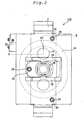
- Figure 7 is a front view, partially cross sectioned, for illustrating a brake mechanism 120 in the third embodiment of the present invention.
- hatched portions and a portion indicated by dotted lines represent cross sections.
- Figure 7 shows, like Figure 1 , a right-hand side portion of the brake mechanism 120, but the actual brake mechanism 120 is symmetrical in the right-and-left direction when viewed from the front.
- the brake mechanism 120 is similar to the brake mechanism 100 in the first embodiment.
- the attachment member 24 mounted on the fixed iron core 2 is provided with a screw portion 66 in place of the tilt adjusting bolt 26 and the locknut 28.
- the screw portion 66 is provided with a locknut 68, and further, a nut 70, a spring receiving member 72, and a small spring 74 are assembled in that order.
- the small spring 74 is in contact with the shoe 6.
- f 1 , f 2 and f 3 each are a pressing force of the small spring 74 acting in the direction such that the shoe 6 is pressed on the brake surface 50
- R 1 , R 2 and R 3 each are a distance between the center of the spherical seat 46 and the center of the small spring 74
- F is an attraction force of the plate spring 38 between the movable iron core 4 and the shoe 6.
- the angle of the shoe 6 is adjusted so that the shoe 6 comes into contact with the brake surface 50, by which the shoe 6 is pressed on the brake surface 50.
- the small spring 74 is provided in a portion in which the tilt at the time of attraction is adjusted.
- the angular moments f 1 ⁇ R 1 , f 2 ⁇ R 2 , and f 3 ⁇ R 3 around the spherical seat 46 caused by the small springs 74 take different values.
- the fixed iron core 2 and the movable iron core 4 are attracted to each other in a contacting state.
- the shoe 6 does not separate from the movable iron core 4 and is always adjusted compulsorily in the direction such that the angular moment due to the tilt of the shoe 6 is balanced by the small spring 74, so that the shoe 6 can be kept parallel with the brake surface 50.
- the screw portion 66, the locknut 68, the nut 70, the spring receiving member 72, and the small spring 74 are installed to the movable iron core 4 in that order.
- the means for adjusting the tilt is not limited to these elements. Any other elastic body may be used if it can keep the angular moment around the spherical seat at a predetermined value in the excited state. Further, as in the second embodiment, these elements may be provided on the shoe 6.
- the screw portion 66 and the like are provided at three locations, but, as in the first embodiment, the number of locations is not limited to three.
- the angular moments around the spherical seat 46 caused by the small springs 74 are made constant at the time of parallel state.
- the present invention is not limited to this configuration.
- the small spring 74 has only to be set so that the angular moments are constant when a predetermined angle is attained.
- Figure 8 is a front view, partially cross sectioned, for illustrating a brake mechanism 130 in the first example .
- hatched portions and dotted lines represent cross sections.
- Figure 8 shows, like Figure 1 , a right-hand side portion of the brake mechanism 130, but the actual brake mechanism 130 is symmetrical in the right-and-left direction when viewed from the front.
- the brake mechanism 130 is similar to the brake mechanism 100 in the first embodiment. However, for the brake mechanism 130, the fixed iron core 2 is not provided with the attachment members 24, the tilt adjusting bolts 26, and the locknuts 28, and the movable iron core 4 is not provided with the through holes 34 corresponding to these elements.
- three tilt adjusting bolts 76 are embedded in the movable iron core 4, and they each are fixed by a locknut 78.
- the center of gravity of a triangle connecting the three tilt adjusting bolts agrees with the center of the spherical seat 46.
- the three tilt adjusting bolts 76 are adjusted so that the movable iron core 4 and the shoe 6 are parallel with each other at the time of excited state. Further, in the unexcited state and in the state in which the movable iron core 4 and the fixed iron core 2 are kept parallel with each other, the distance between the tip end of the tilt adjusting bolt 76 and the shoe 6 is kept at g2.
- the distance g2 is, as in the first embodiment, slightly smaller than the distance g 1 between the attraction surfaces of the movable iron core 4 and the fixed iron core 2.
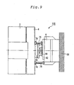
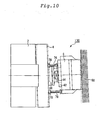
- Figures 9 and 10 are top views for illustrating a state in which the brake of the brake mechanism 130 is applied and released. These top views are, like Figures 3 and 4 , views taken along the line B-B' of Figure 2 . Therefore, the lower portion in the figure shows the front side in Figure 8 .
- the movable iron core 4 tilts, of the tilt adjusting bolts 76 provided on the movable iron core 4, at least one bolt comes into contact with the shoe 6 earlier than other tilt adjusting bolts 76.
- the movable iron core 4 receives a pressing force in the direction of the core 6 from the pressing spring 20.
- the movable iron core 4 inversely receives a pressing force toward the fixed iron core 2.
- the fixed iron core 2 and the movable iron core 4 can be made parallel with each other by making the shoe 6 and the movable iron core 4 parallel with each other.
- the tilt adjusting bolt 76 is pressed on the shoe 6.
- the tilt of the movable iron core 4 is adjusted so that the shoe 6 and the movable iron core 4 are parallel with each other.
- the movable iron core 4 and the shoe 6 can be kept parallel with each other.
- attraction is made in a state in which the movable iron core 4 and the shoe 6 are parallel with each other.
- the fixed iron core 2 and the movable iron core 4 are attracted to each other in a state in which they are in contact with each other on the attraction surfaces. Therefore, an intrinsic state in which the fixed iron core 2 and the movable iron core 4 are parallel with each other and the surface opposed to the movable iron core 4 of the shoe 6 is also parallel with these iron cores is established.
- the brake mechanism 130 even in the excited state, the shoe 60 can be kept parallel with the undeflected original brake surface 50.
- the brake mechanism 140 since the whole surface of the shoe 6 can be pressed on the brake surface 50 in the unexcited state, the brake strength can be secured. Also, in the excited state, the opposed surface of the shoe 6 can be kept parallel with the undeflected original brake surface 50, so that the system can be made small in size.
- the tilt adjusting bolts 76 and the like are disposed on the movable iron core 4.
- the present invention is not limited to this case, and the tilt adjusting bolts may be disposed on the shoe 6.
- tilt adjusting means such as a tilt adjusting bolt 26 such that a through hole 34 is provided in the movable iron core 4 and an attachment member 24 penetrating the through hole 34 is provided to attract the shoe 6 and the fixed iron core 2 in parallel may be provided separately.
- the number of tilt adjusting bolts 76 and the like is not limited to three.
- the three tilt adjusting bolts 76 have the same length, and the center of gravity of a triangle connecting the tilt adjusting bolts 76 agrees with the center of the gap adjusting bolt 44.
- the reason for this is that the shoe 6 and the undeflected original brake surface 50 are made parallel with each other in the excited state by keeping the distance between the movable iron core 4 and the shoe 6 constant.
- the present invention is not limited to this configuration.
- Figure 11 is a front view, partially cross sectioned, for illustrating a brake mechanism 140 in the fifth embodiment of the present invention.
- hatched portions and dotted lines represent cross sections.
- Figure 11 shows, like Figure 1 , a right-hand side portion of the brake mechanism 140, but the actual brake mechanism 140 is symmetrical in the right-and-left direction when viewed from the front.
- the brake mechanism 140 is similar to the brake mechanisms 120 and 130 explained in the third embodiment and the first example.
- the brake mechanism 140 is provided with screw portions 80 each fixed to the movable iron core 4 by a locknut 78. Also, as in the case of the brake mechanism 120, the nut 70, the spring receiving member 72, and the small spring 74 are provided in that order in the screw portion 80, and the small spring 74 is in contact with the shoe 6. That is to say, the brake mechanism 140 is a brake mechanism in which elements similar to the small spring 74 and the like provided in the brake mechanism 120 are installed to the brake mechanism 130.
- the attraction force of the plate spring 38 is set so that F > fi + f2 + f3.
- fx, f2 and f3 each are a pressing force of the small spring 74 acting in the direction such that the shoe 6 is pressed on the brake surface 50
- Ri, R2 and R3 each are a distance between the center of the spherical seat 46 and the center of the small spring 74.
- F is an attraction force of the plate spring 38 between the movable iron core 4 and the shoe 6.
- the shoe 6 and the movable iron core 4 can be kept parallel with each other.
- the movable iron core 4 tilts, of the small springs 74 at the tip ends of the screw portions 80 provided on the movable iron core 4, at least one small spring comes into contact with the shoe 6 earlier than other small springs 74.
- the movable iron core 4 receives a pressing force in the direction of the core 6 from the pressing spring 20.
- the movable iron core 4 inversely receives a pressing force toward the fixed iron core 2.
- the angular moments f 1 ⁇ R 1 , f 2 ⁇ R 2 , and f 3 ⁇ R 3 around the spherical seat caused by the small springs 74 take different values.
- the shoe 6 and the movable iron core 4 are always forced in the direction such that the angular moments are balanced, so that the shoe 6 and the brake surface 50 can be made parallel with each other.
- the shoe 6 does not separate from the movable iron core 4 and is always adjusted compulsorily in the direction such that the angular moments due to the tilt of the shoe 6 are balanced by the small spring 74, so that the shoe 6 can be kept parallel with the brake surface 50.
- the screw portion 80, the locknut 78, the nut 70, the spring receiving member 72, and the small spring 74 are installed to the movable iron core 4 in that order to adjust a tilt.
- these elements may be provided on the shoe 6.
- the present invention is not limited to a configuration in which the small spring is installed. In place of the small spring 74, any other elastic body may be used if it can keep the angular moment at a predetermined value.
- the angular moments caused by the small springs 74 are not limited to ones that are made constant when the movable iron core 4 and the shoe 6 are parallel with each other, and may be ones that are set so as to be constant when the movable iron core 4 and the shoe 6 have a predetermined angle.
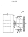
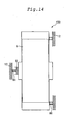
- Figures 12 , 13 and 14 are top views, partially cross sectioned, for illustrating the brake mechanism 150 in the example.
- Figures 12 and 13 show top surfaces corresponding to a portion viewed along the line B-B' of Figure 2 .
- hatched portions and dotted lines represent cross sections.
- the brake mechanism 150 is similar to the brake mechanism 100. However, the fixed iron core 2 of the brake mechanism 150 is not provided with the attachment members 24, the tilt adjusting screws 26, and the locknuts 28, and also the movable iron core 4 is not provided with the through holes 34 corresponding to these elements.
- a side plate 82 is fixed, with adjusting screws 84, to a support plate 12 arranged on the front side (lower side in Figure 12 ) so as to face to the shoe 6.
- the position and tilt of the side plate 82 can be adjusted by the adjusting screws 84.
- the side plate 82 is arranged in the direction perpendicular to the attraction surface of the fixed iron core 2, that is, in the direction in which the shoe 6 is pushed so that the surface opposed to the movable iron core 4 of the shoe 6 becomes parallel with the fixed iron core 2.
- elastic elements 86 are arranged so that a load is applied in the direction in which the side plate 82 is pressed on the support plate 12 on the front side.
- the shoe in the excited state, is arranged in the direction in which the surface opposed to the movable iron core 4 is perpendicular to the movable iron core 4 and the fixed iron core 2, that is, in the direction in which the opposed surface is parallel with the undeflected original brake surface 50.
- the brake mechanism 150 in the unexcited state, the whole surface of the shoe 6 can be pressed on the brake surface 50 so as to match the deflection of the brake surface 50, and in the excited state, the opposed surface of the shoe 6 can be kept parallel with the undeflected original brake surf ace. Therefore, the braking force of brake can be maintained, and also the brake mechanism can be made small in size.
- the brake mechanism 150 may be provided with means for adjusting the tilts of the tilt adjusting bolts 26 and the like as shown in the first to fifth embodiments. Thereby, the horizontal state can be restored more exactly.
- the side plate 82 is provided with the adjusting screws 84 on one side of the shoe 6 and the elastic elements are used on the opposite side.
- the present disclosure is not limited to this configuration.
- the side plate 82 may be provided on both sides of the shoe 6 using the elastic elements to press the shoe 6 in a correct direction.
- Figure 15 is a front view, partially cross sectioned, for illustrating the brake mechanism 160.
- hatched portions represent cross sections.
- Figure 15 shows, like Figure 1 , a right-hand side portion of the brake mechanism 160, but the actual brake mechanism 160 is symmetrical in the right-and-left direction when viewed from the front.
- the brake mechanism 160 is similar to the brake mechanism 100 described in the first embodiment.
- the fixed iron core 2 is not provided with the guide 14, and also the movable iron core 4 is not provided with the guide pin 32.
- the movable iron core 4 has a plate spring 88 on each of its four side surfaces.
- the brake is applied or released by attracting the movable iron core 2 to the fixed iron core 3 or pressing it toward the brake surface 50 by controlling the current flowing in the coil 16.
- the guide pin 32 is caused to penetrate the guide 14, and is moved in the guide 14 so that the movable iron core 4 moves horizontally with respect to the fixed iron core 2.
- the movable iron core 4 is pushed from four sides in the direction perpendicular to the movement direction of the movable iron core 4 by the plate springs 88 provided on the four side surfaces, by which the movable iron core 2 can be moved while keeping the horizontality with respect to the fixed iron core 4.
- the movable iron core 4 has the plate springs 88 provided on the four side surfaces, and thereby can repeat movement while keeping the horizontality with respect to the fixed iron core 2.
- the movement direction of the movable iron core 4 is directed to a predetermined direction by supporting the movable iron core 4 from the four side surfaces. Therefore, the guide 14 can be prevented from wearing with time as compared with the case where the movement direction is directed by the guide 14 and the guide pin 32 in the center of the brake mechanism. As a result, the increase in tilt of the movable iron core 4 can be restrained.
- plate springs 88 are provided on the four side surfaces of the movable iron core.
- the present invention is not limited to this configuration.
- plate springs may be provided on the four side surfaces of the shoe 6.
- the number of the plate springs 88 is not limited to four.
- the number of the plate springs 88 may be four or more or four or less if the plate springs 88 can guide the movable iron core 4 in the movement direction: for example, the plate springs 88 may be provided on the opposed two surfaces only, or two plate springs 88 may be provided on each one side surface.
- the plate springs 88 used as elements for directing the movement direction.
- the present invention is not limited to this configuration.
- any other elastic body that directs the movement direction can be used.
- the brake mechanism 160 explained in the fourth embodiment is provided with the tilt adjusting bolts 26 and the like.
- the present invention is not limited to this configuration. Any other means for adjusting the tilt as explained in the first to third embodiments or the examples may be used.
- Figure 16 is a front view, partially cross sectioned, for illustrating the brake mechanism 170 in the eighth embodiment of the present invention.
- hatched portions represent cross sections.
- Figure 16 shows, like Figure 1 , a right-hand side portion of the brake mechanism 170, but the actual brake mechanism 170 is symmetrical in the right-and-left direction when viewed from the front.
- the brake mechanism 170 is similar to the brake mechanism 100, but the brake mechanism 170 is provided with a guide 90 shorter than the guide 14 provided in the fixed iron core 2 of the brake mechanism 100. Also, the movable iron core 4 is provided with a guide pin 92 at a position corresponding to the guide 90. The guide 90 in the fixed iron core 2 is somewhat larger than the guide pin 92, so that a gap is provided therebetween. In this gap portion, an O-ring 94 is arranged. This O-ring 94 is an elastic body.
- the movable iron core 4 is attracted to the fixed iron core 2, or the shoe 6 is pressed on the brake surface 50 by the movement of the movable iron core 4, by which the brake is applied or released.
- the guide 90 is somewhat larger than the guide pin 92, the guide pin 92 is fitted in the guide 90 with a gap being provided, and the O-ring, which is an elastic body, is arranged in this gap portion. Therefore, the guide pin 92 can move in the guide 90 in a state of being tilted to some extent. Even in this construction, the guide pin 92 does not come in direct contact with the inside surface of the guide 90, and the O-ring 94 comes in direct contact with the inside surface of the guide 90. Therefore, even if the guide pin 92 moves in the guide 90, the wear of the inside surface of the guide 90 can be restrained.
- the present invention is not limited to this case.
- the brake mechanism having other means for adjusting a tilt as in the case of the brake mechanisms 110 to 150 in place of the guide 14 and the guide pin 32, the guide 90, the guide pin 92, and the O-ring 94 may be provided as in the case of the brake mechanism 170.
- Figure 17 is a front view, partially cross sectioned, for illustrating the brake mechanism 180.
- hatched portions represent cross sections.
- Figure 17 shows, like Figure 1 , a right-hand side portion of the brake mechanism 180, but the actual brake mechanism 180 is symmetrical in the right-and-left direction when viewed from the front.
- the brake mechanism 180 is similar to the brake mechanism 170 in the fifth embodiment. However, the brake mechanism 180 is not provided with the guide 90 and the guide pin 92.
- the spring receiving member 18 for the pressing spring 20 which is provided at two locations in the fixed iron core 2 is provided with an O-ring 96.
- the O-ring 96 is arranged so that a load is applied in the direction perpendicular to the load direction of attraction force. Also, a part of the spring receiving member 18 is embedded in the movable iron core 4.
- the movable iron core 4 is attracted to the fixed iron core 2, or the shoe 6 is pressed on the brake surface 50 by the force of the pressing spring 20 pushing the movable iron core 4, by which the brake is applied or released.
- a part of the spring receiving member 18 provided in the fixed iron core 2 of the brake mechanism 180 is fixed to the movable iron core 4.
- the O-ring 96 is provided around the spring receiving member 18, by which a load is applied in the direction perpendicular to the movement direction of the movable iron core 4. Therefore, the movable iron core 4 is guided by the movement of the spring receiving member 18 supported by the O-ring, and thus is attracted to the fixed iron core 2 or is pressed toward the shoe 6.
- the movement of the movable iron core 4 can be guided by the spring receiving member 18 and the O-ring 96 provided at two locations of the fixed iron core. Therefore, the movable iron core 4 can be moved without a problem in that the movable iron core 4 is tilted by the wear of the guide.
- Figure 18 is a front view, partially cross sectioned, for illustrating the brake mechanism 190.
- hatched portions represent cross sections.
- Figure 18 shows, like Figure 1 , a right-hand side portion of the brake mechanism 190, but the actual brake mechanism 190 is symmetrical in the right-and-left direction when viewed from the front.
- the brake mechanism 190 is similar to the brake mechanism 100. However, in the brake mechanism 190, a cut-off groove 98 is provided on the brake surface 50 side of the shoe 6. In the cut-off groove 98, the locknut 42 for the gap adjusting bolt 44 is arranged.
- Figure 19 is an enlarged sectional view of the gap adjusting bolt 44.
- Figures 19(a) and 19(b) show a case where the gap adjusting bolt 44 is provided on the movable iron core 4 side of the shoe
- Figures 19(c) and 19(d) show a case where the gap adjusting bolt 44 is provided on the brake surface 50 side of the shoe 6.
- the shoe 6 receives a reaction Fs from the brake surface with respect to a pressing force Fb of the pressing spring 20.
- the threaded portion of the shoe 6 receives a force in the same direction as that of Fs (left direction in Figure 19 ) with respect to the threaded portion of the gap adjusting bolt 44.
- the gap adjusting bolt 44 is locked by the locknut 42, an axial force is generated in the threaded portion of the gap adjusting bolt 44, so that the thread face of the locknut 42 receives a force in the same direction as that of Fs (left direction in Figure 19 ) with respect to the thread face of the gap adjusting bolt 44.
- the thread face of the shoe 6 receives a force in the same direction as that of Fb (right direction in Figure 19 ) with respect to the thread face of the gap adjusting bolt 44. Also, the thread face of the shoe 6 receives a force in the same direction as that of Fb (right direction in Figure 19 ) with respect to the thread face of the gap adjusting bolt 44. Therefore, the shoe stroke measured before the gap adjusting bolt 44 is locked by the locknut 42 moves to the left side so as to correspond to the reaction, by which g 1 is shortened by a distance of the small gap.
- the gap g 1 between the attraction surfaces can be set so as to be small, the system can be made small in size, and also a low-noise brake can be obtained.
- the cut-off groove 98 is provided in the central portion of the shoe 6 that faces to the brake surface.
- the friction coefficient is increased by the wedge effect. For example, if a groove angle of 30 degrees is provided with respect to the extension angle of 60 degrees, the apparent friction coefficient increases by 8%.
- the brake mechanism can further be made small in size, so that a space-saving and low-cost brake system can be obtained.
- a fixed member, a movable member, and a braking member in the present invention correspond to, for example, the fixed iron core 2, the movable iron core 4, and the shoe 6 in the embodiments of the present invention, respectively.
- An elastic member in the present invention corresponds to the pressing spring 20 in the embodiments of the present invention.
- a connecting portion in the present invention indicates the connecting portion between the movable iron core 4 and the shoe 6 in the embodiments of the present invention
- a brake surface side adjusting member corresponds to, for example, thegapadjustingbolt 44, the spherical seat 46, the spherical seat receiving member 36, and the plate spring 38, or the gap adjusting bolt 62, the spherical seat 64, the spherical seat receiving member 56, the plate spring 58, and the like in the embodiments of the present invention.
- a body portion of the present invention corresponds to, for example, the gap adjusting bolt 44, 62 in the embodiments of the present invention, and a support member corresponds to the plate spring 38, 58 in the embodiments of the present invention.
- a concave portion in the present invention corresponds to, for example, the cut-off groove 98 in the embodiment of the present invention.
- a fixed member side adjusting member or a protruding portion in the present invention corresponds to the attachment member 24, the tilt adjusting bolt 26, and the locknut 28 in the first and seventh to tenth embodiments, the attachment member 24, the tilt adjusting bolt 52, and the locknut 54 in the second embodiment, or the attachment member 24, the screw portion 66, the locknut 68, the nut 70, the spring receiving member 72, the small spring 74, and the like in the third embodiment.
- an opposed portion in the embodiment of the present invention corresponds to the attachment member 24 in the second embodiment
- an elastic member for protruding portion corresponds to, for example, the small spring in the third embodiment.
- a movable member side adjusting member or a protruding portion in the present invention corresponds to, for example, the tilt adjusting bolt 76 and the locknut 78 in the fourth embodiment or the locknut 78, the screw portion 80, the nut 70, the spring receiving member 72, and the small spring 74 in the second example.
- An elastic member for side plate in the present invention corresponds to the elastic element 86 in figures 12-14 .
- a through hole in the present invention corresponds to, for example, the guide 14 according to figures 1-11 . and an axis corresponds to, for example, the guide pin 32 in the first to third embodiments.
- an engagement hole, an engagement element, and an elastic member for engagement hole correspond to, for example, the guide 90, the guide pin 92, and the O-ring 94 in the fifth embodiment, respectively.
- an elastic member receiving member in the present invention corresponds to, for example, the spring receiving member 18 in the sixth embodiment, and an elastic member for elastic member receiving member corresponds to the O-ring 96 in the sixth embodiment.
- an elastic member for movable member in the present invention corresponds to, for example, the plate spring 88 in the fourth embodiment.
- the tilt of connection between the braking member and the movable member can be adjusted in the connecting portion between the movable member and the braking member. Therefore, even when the brake surface deflects, at the time of brake release, the braking member and the brake surface can be adjusted so as to be parallel with each other, so that the shoe is prevented from coming into contact with the brake surface. Thereby, the occurrence of wear between the shoe and the brake surface can be restrained, and thus the braking force of the brake mechanism can be maintained.
- the brake mechanism in which when the fixed member and the movable member are attracted to each other, the distance between the fixed member or the movable member and the braking member can be adjusted, in the attracted state, the braking member and the undeflected original brake surface can be kept parallel with each other. Therefore, the distance between the brake surface and the braking member and the distance between the attraction surfaces of the movable iron core and the fixed iron core can be shortened to some degree. As a result, a high attraction force is not needed, and the brake mechanism can be made small in size.
- the brake mechanism provided with a mechanism in which when the movable iron core moves, the movement direction of the movable iron core is directed, the movement direction of the movable member can be directed to a proper direction, so that a shift caused by the movement of the movable member and the braking member can be restrained. Therefore, the brake mechanism can be made small in size.
Landscapes
- Engineering & Computer Science (AREA)
- General Engineering & Computer Science (AREA)
- Mechanical Engineering (AREA)
- Physics & Mathematics (AREA)
- Electromagnetism (AREA)
- Civil Engineering (AREA)
- Structural Engineering (AREA)
- Braking Arrangements (AREA)
- Cage And Drive Apparatuses For Elevators (AREA)
Claims (11)
- Bremsmechanismus (100; 110; 120; 130; 140; 150; 160; 170; 180; 190) für eine Aufzugsmaschine, mit:einem ortsfesten Element (2);einem beweglichen Element (4), das dem ortsfesten Element (2) zugewandt ist; undeinem Bremselement (6), das an einer Fläche mit dem beweglichen Element (4) in Verbindung steht, und einer Bremsfläche (50), die in einem drehenden Abschnitt der Aufzugsmaschine an der Fläche gegenüber der einen Fläche vorgesehen ist, zugewandt ist, wobeidas ortsfeste Element (2) aufweist:ein elastisches Element (20), welches das bewegliche Element (4) zusammen mit dem Bremselement (6) zu der Bremsfläche (50) hin drückt; undeine Spule (16) zum Anziehen des beweglichen Elements (4) zusammen mit dem Bremselement (6) zu dem ortsfesten Element (2), indem bewirkt wird, dass ein Strom fließt, und wobeiein Verbindungsabschnitt zwischen dem beweglichen Element (4) und dem Bremselement (6) ein bremsflächenseitiges Einstellelement (44, 46, 36, 38; 62, 64, 56, 58) zum Einstellen der Neigung des Bremselements (6) aufweist,wobei der Bremsmechanismus für eine Aufzugsmaschine ferner ein Einstellelement auf der Seite des ortsfesten Elements (24, 26, 28; 24, 52, 54; 24, 66, 68, 70, 72, 74) zum Einstellen des Abstands zwischen dem ortsfesten Element (2) und dem Bremselement (6), wenn das bewegliche Element (4) zu dem ortsfesten Element (2) hin angezogen wird, aufweist,dadurch gekennzeichnet, dassdas Einstellelement auf der Seite des ortsfesten Elements (24, 26, 28; 24, 52, 54; 24, 66, 68, 70, 72, 74) mehrere hervorstehende Abschnitte aufweist, die derart vorgesehen sind, dass sie das bewegliche Element (4) von dem ortsfesten Element (2) durchdringen, unddie Vorderenden der hervorstehenden Abschnitte in Kontakt mit dem Bremselement (6) kommen, wenn das bewegliche Element (4) zu dem ortsfesten Element (2) hin angezogen wird oder das Einstellelement an der Seite des ortsfesten Elements (24, 26, 28; 24, 52, 54; 24, 66, 68, 70, 72, 74) aufweist:mehrere hervorstehende Abschnitte (52) die an dem Bremselement (6) vorgesehen sind und zu dem ortsfesten Element (2) hin hervorstehen; und wobeigegenüberliegende Abschnitte (24), die an dem ortsfesten Element (2) vorgesehen sind und an Positionen gegenüber den hervorstehenden Abschnitten, durch das bewegliche Element (4) hervorstehen, unddas Vorderende des hervorstehenden Abschnitts (52) und das Vorderende des gegenüberliegenden Abschnitts (24) miteinander in Kontakt kommen, wenn das bewegliche Element (4) zu dem ortsfesten Element (2) hin angezogen wird.
- Bremsmechanismus für eine Aufzugsmaschine gemäß Anspruch 1, bei dem die hervorstehenden Abschnitte jeweils ein elastisches Element (74) als hervorstehenden Abschnitt an dem Vorderende desselben aufweisen.
- Bremsmechanismus für eine Aufzugsmaschine gemäß einem der Ansprüche 1 bis 2, bei dem
das Einstellelement an der Seite des ortsfesten Elements (24, 26, 28; 24, 52, 54; 24, 66, 68, 70, 72, 74) drei der hervorstehenden Abschnitte aufweist,
alle der drei hervorstehenden Abschnitte dieselbe Länge aufweisen, und
der Schwerpunkt eines Dreiecks, das die hervorstehenden Abschnitte verbindet, mit dem Zentrum des Verbindungsabschnitts übereinstimmt. - Bremsmechanismus für eine Aufzugsmaschine gemäß einem der Ansprüche 1 bis 3, bei dem
das bremsflächenseitige Einstellelement (44, 46, 36, 38; 62, 64, 56, 58) aufweist:einen Körperabschnitt (44; 62) dessen Vorderende als kugelförmige Fläche ausgebildet ist;ein kugelförmiges Sitzaufnahmeelement (36; 56) das in Kontakt mit der kugelförmigen Fläche steht; undein Haltelement (38; 58), das zum Halten des Körperabschnitts (44; 62) in einem Zustand in dem der Körperabschnitt (44; 62) sich geringfügig auf dem Sitzaufnahmeelement (36; 56) bewegen kann, um das kugelförmige Sitzaufnahmeelement (36; 56) angeordnet ist, unddie Neigung des Bremselements (6) durch Verschieben der kugelförmigen Fläche auf dem kugelförmigen Sitzaufnahmeelement (36; 56) einstellt wird. - Bremsmechanismus für eine Aufzugsmaschine gemäß Anspruch 4, bei dem
ein Körperabschnitt (44) mit dem Bremselement (6) verbunden ist, und
das kugelförmige Sitzaufnahmeelement (36) und das Halteelement (38) mit dem beweglichen Element (4) verbunden sind. - Bremsmechanismus für eine Aufzugsmaschine gemäß Anspruch 5, bei dem
das Bremselement (6) einen konkaven Abschnitt (98) in einer Fläche, die der Bremsfläche (50) zugewandt ist, aufweist,
der Körperabschnitt (44) einen Schraubenabschnitt, der das Bremselement (6) durchdringt und einen Mutterabschnitt (42) der mit dem Schraubenabschnitt eingreift, aufweist, und
der Schraubenabschnitt durch den Mutterabschnitt (42), der in dem konkaven Abschnitt (98) angeordnet ist, befestigt ist. - Bremsmechanismus für eine Aufzugsmaschine gemäß Anspruch 4, bei dem
der Körperabschnitt (62) mit dem beweglichen Element (4) verbunden ist, und
das kugelförmige Sitzaufnahmeelement und das Halteelement mit dem Bremselement (6) verbunden sind. - Bremsmechanismus für eine Aufzugsmaschine gemäß einem der Ansprüche 1 bis 7, bei dem
das ortsfeste Element (2) eine Durchgangsöffnung (14) in dessen Zentrum aufweist,
das bewegliche Element (4) eine Achse (32) in dessen Zentrum aufweist,
die Achse (32) das Durchgangsloch (14) durchdringt, und sich die Achse (32) in die Durchgangsöffnung (14) bewegt, wenn sich das bewegliche Element (4) zu dem ortsfesten Element (2) hin oder zu der Bremsfläche (50) hin bewegt. - Bremsmechanismus für eine Aufzugsmaschine gemäß einem der Ansprüche 1 bis 8, bei dem
das ortsfeste Element (2) eine Eingriffsöffnung (90) mit einem Bodenabschnitt in dessen Zentrum aufweist,
das bewegliche Element (4) ein Eingriffselement (92), das mit dem Eingriffsabschnitt (90) eingreift, aufweist,
das Eingriffselement (92) ein elastisches Element (94) für die Eingriffsöffnung (90) aufweist, das in einem Spalt, der zwischen der Eingriffsöffnung (90) und dem Eingriffselement (92) vorgesehen ist, und
sich das Eingriffselement (92) in die Eingriffsöffnung (90) bewegt, wenn sich das bewegliche Element (4) zu dem ortsfesten Element (2) hin oder zu der Bremsfläche (50) hin bewegt. - Bremsmechanismus für eine Aufzugsmaschine gemäß einem der Ansprüche 1 bis 9, bei dem
das ortsfeste Element (2) ein Aufnahmeelement für das elastische Element (18) aufweist, das in einer Position gegenüber dem elastischen Element (20) vorgesehen ist,
ein Teil des Aufnahmeelements für das elastische Element (18) mit dem beweglichen Element (4) verbunden ist,
ein elastisches Element für das Aufnahmeelement für das elastische Element (96) um das Aufnahmeelement für das elastische Element (18) herum, vorgesehen ist, und
sich das Aufnahmeelement für das elastische Element (18) zusammen mit dem beweglichen Element (4) bewegt, wenn sich das bewegliche Element (4) zu dem ortsfesten Element (2) hin oder zu der Bremsfläche (50) hin bewegt. - Bremsmechanismus für eine Aufzugsmaschine gemäß einem der Ansprüche 1 bis 10, bei dem der Bremsmechanismus für eine Aufzugsmaschine ferner ein elastisches Element für ein bewegliches Element (88) aufweist, das an einer gegenüberliegenden Position zu dem beweglichen Element (4), zum Aufbringen einer Last in der zentralen Richtung des beweglichen Elements (4) und in der Richtung senkrecht zu der Bewegungsrichtung des beweglichen Elements (4), vorgesehen ist.
Priority Applications (2)
| Application Number | Priority Date | Filing Date | Title |
|---|---|---|---|
| EP12177275.0A EP2514988B1 (de) | 2002-10-18 | 2002-10-18 | Bremsmechanismus für Zugmaschine |
| EP12189557.7A EP2551545B1 (de) | 2002-10-18 | 2002-10-18 | Bremsmechanismus für Hebezug |
Applications Claiming Priority (1)
| Application Number | Priority Date | Filing Date | Title |
|---|---|---|---|
| PCT/JP2002/010822 WO2004036080A1 (ja) | 2002-10-18 | 2002-10-18 | 巻上機用ブレーキ機構 |
Related Child Applications (4)
| Application Number | Title | Priority Date | Filing Date |
|---|---|---|---|
| EP12189557.7A Division EP2551545B1 (de) | 2002-10-18 | 2002-10-18 | Bremsmechanismus für Hebezug |
| EP12177275.0A Division EP2514988B1 (de) | 2002-10-18 | 2002-10-18 | Bremsmechanismus für Zugmaschine |
| EP12177275.0 Division-Into | 2012-07-20 | ||
| EP12189557.7 Division-Into | 2012-10-23 |
Publications (3)
| Publication Number | Publication Date |
|---|---|
| EP1553319A1 EP1553319A1 (de) | 2005-07-13 |
| EP1553319A4 EP1553319A4 (de) | 2007-08-29 |
| EP1553319B1 true EP1553319B1 (de) | 2013-06-12 |
Family
ID=32104833
Family Applications (3)
| Application Number | Title | Priority Date | Filing Date |
|---|---|---|---|
| EP12189557.7A Expired - Lifetime EP2551545B1 (de) | 2002-10-18 | 2002-10-18 | Bremsmechanismus für Hebezug |
| EP02777879.4A Expired - Lifetime EP1553319B1 (de) | 2002-10-18 | 2002-10-18 | Bremsmechanismus für hebezeug |
| EP12177275.0A Expired - Lifetime EP2514988B1 (de) | 2002-10-18 | 2002-10-18 | Bremsmechanismus für Zugmaschine |
Family Applications Before (1)
| Application Number | Title | Priority Date | Filing Date |
|---|---|---|---|
| EP12189557.7A Expired - Lifetime EP2551545B1 (de) | 2002-10-18 | 2002-10-18 | Bremsmechanismus für Hebezug |
Family Applications After (1)
| Application Number | Title | Priority Date | Filing Date |
|---|---|---|---|
| EP12177275.0A Expired - Lifetime EP2514988B1 (de) | 2002-10-18 | 2002-10-18 | Bremsmechanismus für Zugmaschine |
Country Status (5)
| Country | Link |
|---|---|
| EP (3) | EP2551545B1 (de) |
| JP (1) | JP4229911B2 (de) |
| KR (1) | KR100605771B1 (de) |
| CN (3) | CN100516581C (de) |
| WO (1) | WO2004036080A1 (de) |
Families Citing this family (8)
| Publication number | Priority date | Publication date | Assignee | Title |
|---|---|---|---|---|
| JPWO2007108112A1 (ja) | 2006-03-22 | 2009-07-30 | 三菱電機株式会社 | エレベータ用巻上機のブレーキ装置 |
| WO2008087735A1 (ja) * | 2007-01-19 | 2008-07-24 | Mitsubishi Electric Corporation | エレベータのブレーキ装置 |
| KR100823147B1 (ko) | 2007-08-27 | 2008-04-21 | 한국기계부품(주) | 엘리베이터용 브레이크 장치 |
| CN101977836B (zh) * | 2008-06-02 | 2013-04-24 | 三菱电机株式会社 | 电梯用曳引机的制动装置 |
| CN203095493U (zh) * | 2012-12-31 | 2013-07-31 | 杭州沪宁电梯配件有限公司 | 内置斜面增力机构的电磁铁 |
| DE102014215918B4 (de) * | 2014-08-12 | 2016-07-28 | Saf-Holland Gmbh | Bremseinheit |
| CN112228479B (zh) * | 2020-10-26 | 2023-02-03 | 上海三菱电梯有限公司 | 电梯曳引机用制动器及其实现方法 |
| KR102771962B1 (ko) | 2024-07-04 | 2025-02-25 | 주식회사 비티알수성 | 엘리베이터 브레이크 가동판 작동용 스위치 |
Family Cites Families (9)
| Publication number | Priority date | Publication date | Assignee | Title |
|---|---|---|---|---|
| JPS5546716Y2 (de) * | 1976-04-08 | 1980-11-01 | ||
| JPS5511980U (de) * | 1978-07-12 | 1980-01-25 | ||
| JPS5983225U (ja) * | 1982-11-27 | 1984-06-05 | 日産自動車株式会社 | デイスクブレ−キにおけるパツドの取付構造 |
| US4974829A (en) | 1985-06-10 | 1990-12-04 | Portable Hyperbarics, Inc. | Hyperbaric chamber |
| JPH02265891A (ja) * | 1989-04-05 | 1990-10-30 | Mitsubishi Electric Corp | エレベータのブレーキ装置 |
| JPH11351269A (ja) * | 1998-06-10 | 1999-12-24 | Kubota Corp | 球面軸受けの角度規制構造 |
| JP2000143131A (ja) * | 1998-11-06 | 2000-05-23 | Mitsubishi Electric Corp | エレベーター用制動装置 |
| JP3519642B2 (ja) * | 1999-08-19 | 2004-04-19 | 三陽工業株式会社 | 巻上機用制動装置のパッド保持構造 |
| JP3635035B2 (ja) * | 2001-02-15 | 2005-03-30 | 三陽工業株式会社 | ブレーキ装置 |
-
2002
- 2002-10-18 EP EP12189557.7A patent/EP2551545B1/de not_active Expired - Lifetime
- 2002-10-18 CN CNB2006101111789A patent/CN100516581C/zh not_active Expired - Lifetime
- 2002-10-18 JP JP2004544707A patent/JP4229911B2/ja not_active Expired - Fee Related
- 2002-10-18 KR KR1020047009480A patent/KR100605771B1/ko not_active Expired - Fee Related
- 2002-10-18 EP EP02777879.4A patent/EP1553319B1/de not_active Expired - Lifetime
- 2002-10-18 CN CNB028252608A patent/CN1297758C/zh not_active Expired - Lifetime
- 2002-10-18 EP EP12177275.0A patent/EP2514988B1/de not_active Expired - Lifetime
- 2002-10-18 CN CNB2006101111793A patent/CN100529455C/zh not_active Expired - Lifetime
- 2002-10-18 WO PCT/JP2002/010822 patent/WO2004036080A1/ja not_active Ceased
Also Published As
| Publication number | Publication date |
|---|---|
| EP2551545B1 (de) | 2014-07-16 |
| CN1927694A (zh) | 2007-03-14 |
| EP2551545A1 (de) | 2013-01-30 |
| KR20040071217A (ko) | 2004-08-11 |
| EP2514988B1 (de) | 2014-08-27 |
| CN100529455C (zh) | 2009-08-19 |
| JPWO2004036080A1 (ja) | 2006-02-16 |
| CN1927693A (zh) | 2007-03-14 |
| KR100605771B1 (ko) | 2006-07-31 |
| EP2514988A1 (de) | 2012-10-24 |
| CN100516581C (zh) | 2009-07-22 |
| CN1604998A (zh) | 2005-04-06 |
| JP4229911B2 (ja) | 2009-02-25 |
| CN1297758C (zh) | 2007-01-31 |
| EP1553319A4 (de) | 2007-08-29 |
| WO2004036080A1 (ja) | 2004-04-29 |
| EP1553319A1 (de) | 2005-07-13 |
Similar Documents
| Publication | Publication Date | Title |
|---|---|---|
| EP1553319B1 (de) | Bremsmechanismus für hebezeug | |
| KR100463936B1 (ko) | 레일브레이크 | |
| US10316909B2 (en) | Disc brake, brake caliper, and brake rotary lever | |
| JPS58106232A (ja) | デイスクブレ−キ | |
| AU2012358572B2 (en) | Arrangement for a lift | |
| EP1538123B1 (de) | Bremsvorrichtung für aufzugshebezeug | |
| KR100683319B1 (ko) | 권상기의 브레이크 기구 | |
| JP2003201080A (ja) | エレベーター巻上機の電磁制動装置 | |
| JP4366671B2 (ja) | ノズルフラッパー型サーボバルブ | |
| JP4837639B2 (ja) | ブレーキ装置 | |
| US5007459A (en) | Hydraulic control system | |
| JP6606456B2 (ja) | 電磁ブレーキ装置 | |
| JP4774387B2 (ja) | 巻上機のブレーキ | |
| US4392423A (en) | Printing hammer driving apparatus | |
| JP4455042B2 (ja) | エレベーター用巻上機 | |
| JP2004076899A (ja) | エレベータ巻上機のブレーキ装置 | |
| JP2007292253A (ja) | 巻上機のブレーキ装置 | |
| EP1522757A1 (de) | Elektromagnetische bremse | |
| JP2022083318A (ja) | 産業車両用駐車ブレーキ | |
| JP2000055090A (ja) | ドラムブレーキ装置 | |
| JPH08119094A (ja) | 倍力装置 | |
| GB2351782A (en) | Electro-magnetically releasable brake | |
| JP2007278392A (ja) | ソレノイドバルブ装置 | |
| JPS6147340B2 (de) |
Legal Events
| Date | Code | Title | Description |
|---|---|---|---|
| PUAI | Public reference made under article 153(3) epc to a published international application that has entered the european phase |
Free format text: ORIGINAL CODE: 0009012 |
|
| 17P | Request for examination filed |
Effective date: 20040608 |
|
| AK | Designated contracting states |
Kind code of ref document: A1 Designated state(s): AT BE BG CH CY CZ DE DK EE ES FI FR GB GR IE IT LI LU MC NL PT SE SK TR |
|
| RBV | Designated contracting states (corrected) |
Designated state(s): DE |
|
| RAP1 | Party data changed (applicant data changed or rights of an application transferred) |
Owner name: MITSUBISHI DENKI KABUSHIKI KAISHA |
|
| A4 | Supplementary search report drawn up and despatched |
Effective date: 20070727 |
|
| RIC1 | Information provided on ipc code assigned before grant |
Ipc: B66B 11/08 20060101ALI20070723BHEP Ipc: F16D 65/14 20060101ALI20070723BHEP Ipc: B66D 5/08 20060101ALI20070723BHEP Ipc: F16D 51/12 20060101AFI20040504BHEP |
|
| 17Q | First examination report despatched |
Effective date: 20090917 |
|
| GRAP | Despatch of communication of intention to grant a patent |
Free format text: ORIGINAL CODE: EPIDOSNIGR1 |
|
| GRAS | Grant fee paid |
Free format text: ORIGINAL CODE: EPIDOSNIGR3 |
|
| GRAA | (expected) grant |
Free format text: ORIGINAL CODE: 0009210 |
|
| AK | Designated contracting states |
Kind code of ref document: B1 Designated state(s): DE |
|
| REG | Reference to a national code |
Ref country code: DE Ref legal event code: R096 Ref document number: 60245101 Country of ref document: DE Effective date: 20130808 |
|
| PLBE | No opposition filed within time limit |
Free format text: ORIGINAL CODE: 0009261 |
|
| STAA | Information on the status of an ep patent application or granted ep patent |
Free format text: STATUS: NO OPPOSITION FILED WITHIN TIME LIMIT |
|
| 26N | No opposition filed |
Effective date: 20140313 |
|
| REG | Reference to a national code |
Ref country code: DE Ref legal event code: R097 Ref document number: 60245101 Country of ref document: DE Effective date: 20140313 |
|
| PGFP | Annual fee paid to national office [announced via postgrant information from national office to epo] |
Ref country code: DE Payment date: 20151013 Year of fee payment: 14 |
|
| REG | Reference to a national code |
Ref country code: DE Ref legal event code: R119 Ref document number: 60245101 Country of ref document: DE |
|
| PG25 | Lapsed in a contracting state [announced via postgrant information from national office to epo] |
Ref country code: DE Free format text: LAPSE BECAUSE OF NON-PAYMENT OF DUE FEES Effective date: 20170503 |