EP1557587A2 - Triebwagen-Achsgetriebe - Google Patents
Triebwagen-Achsgetriebe Download PDFInfo
- Publication number
- EP1557587A2 EP1557587A2 EP03025145A EP03025145A EP1557587A2 EP 1557587 A2 EP1557587 A2 EP 1557587A2 EP 03025145 A EP03025145 A EP 03025145A EP 03025145 A EP03025145 A EP 03025145A EP 1557587 A2 EP1557587 A2 EP 1557587A2
- Authority
- EP
- European Patent Office
- Prior art keywords
- input shaft
- railcar
- shaft
- bevel pinion
- axle
- Prior art date
- Legal status (The legal status is an assumption and is not a legal conclusion. Google has not performed a legal analysis and makes no representation as to the accuracy of the status listed.)
- Granted
Links
Images

Classifications
-
- B—PERFORMING OPERATIONS; TRANSPORTING
- B61—RAILWAYS
- B61C—LOCOMOTIVES; MOTOR RAILCARS
- B61C9/00—Locomotives or motor railcars characterised by the type of transmission system used; Transmission systems specially adapted for locomotives or motor railcars
- B61C9/08—Transmission systems in or for locomotives or motor railcars with IC reciprocating piston engines
- B61C9/10—Transmission systems in or for locomotives or motor railcars with IC reciprocating piston engines mechanical
- B61C9/12—Transmission systems in or for locomotives or motor railcars with IC reciprocating piston engines mechanical with change-speed gearing
-
- F—MECHANICAL ENGINEERING; LIGHTING; HEATING; WEAPONS; BLASTING
- F16—ENGINEERING ELEMENTS AND UNITS; GENERAL MEASURES FOR PRODUCING AND MAINTAINING EFFECTIVE FUNCTIONING OF MACHINES OR INSTALLATIONS; THERMAL INSULATION IN GENERAL
- F16H—GEARING
- F16H3/00—Toothed gearings for conveying rotary motion with variable gear ratio or for reversing rotary motion
- F16H3/02—Toothed gearings for conveying rotary motion with variable gear ratio or for reversing rotary motion without gears having orbital motion
- F16H3/08—Toothed gearings for conveying rotary motion with variable gear ratio or for reversing rotary motion without gears having orbital motion exclusively or essentially with continuously meshing gears, that can be disengaged from their shafts
- F16H3/14—Gearings for reversal only
Definitions
- the invention relates to a railcar axle drive according to the preamble of the main claim and a railcar in order to.
- axle drives which of an in Fumblerzeug-longitudinally oriented propeller shaft driven and the drive power on a wheelset axle transmitted, which between a left and a right driven rail wheel is arranged.
- the PTO shaft can be driven directly by a drive motor or from a variable ratio transmission, which is arranged between the propeller shaft and the drive motor is.
- the axis of rotation of the input shaft of the transaxle or the propeller shaft extends above the wheelset.
- the input shaft drives a first spur gear, which in constant mesh with a second spur gear is, which is arranged on a bevel pinion shaft.
- the Bevel pinion of the bevel pinion shaft is meshing with a arranged on the wheelset axle, output side Bevel gear.
- the input shaft and the bevel pinion shaft are one above the other or arranged diagonally above one another, so that they have at least one vertical center distance component.
- the spur gear is part of a switchable spur gear reversing gear, which a forward and has a reverse gear.
- the invention is therefore based on the object Specify axle, in which, compared with known Axles, a higher transmission capacity for the same vertical space is achieved or the same transmission capacity with a smaller vertical space.
- the bevel pinion with respect to the output side bevel gear has a misalignment down to the vertical Distance between the wheel axle and the axis of rotation of Reduce input shaft.
- the occupied by the transmission vertical space is reduced by the amount of misalignment.
- a large wheelbase available for the transmission of high torques is required and ensures the desired translation.
- the bevel pinion and the output side bevel gear hypoid teeth and have a so-called plus-axis offset on.
- the helix angle of the pinion is around an amount dependent on the misalignment greater than Helix angle of the ring gear. This has a bigger one Diameter of the bevel pinion and a higher degree of coverage the Veryakept result, on the one hand the transmission capability is increased and on the other hand gear noise be reduced.
- the invention has the input shaft and the bevel pinion shaft next to the vertical center distance also a horizontal one Center distance component on, so that the input shaft runs obliquely over the bevel pinion shaft.
- the invention is the center distance between the Input shaft and bevel pinion shaft - at the same vertical Overall height of the gearbox - increased.
- the horizontal one the center distance component can not be increased arbitrarily are, as well as the space left and right of the vehicle's longitudinal axis is limited.
- the Railcar ground can run deeper by a further amount, if it is in the area of the highest point of the axle drive housing has a recess into which the Achsgetriebegephaseuse protruding from below.
- the input shaft of the transaxle and 4 denotes the cut wheelset axle, which is orthogonal to the drawing plane.
- the input shaft 2 is rotatable by means of two tapered roller bearings 6, 8 stored in a socket 10 of the gear housing 12. At its outer end, it has a flange 14 which provided for attachment of a propeller shaft, not shown is, which runs in extension of the input shaft and with the drive motor or an intermediate Step change gear is connected.
- two spur gears 16, 18 are arranged.
- the Sliding sleeve 20 is rotationally fixed by means of a toothing, however axially displaceable, arranged on the input shaft 2. It is of a pneumatic switching device 22nd actuated.
- the sliding sleeve engages 20 with its external teeth 24 in an internal toothing 26 of the left spur gear, in its right end position in an internal toothing 28 of the right spur gear 18, so that either the first spur gear 16 or the second spur gear 18 is rotatably driven by the input shaft 2.
- the two Spur gears 16, 18 are each provided with a pair of tapered roller bearings stored on housing neck.
- the switching device 22 is with its inner part radially within the Spur gear 16 arranged.
- the spur gear 16 is in constant Tooth engagement with the arranged on the bevel pinion shaft Spur gear 30.
- the drive connection between the spur gear 18 and the spur gear 30 is not shown by a Intermediate shaft made on the two spur gears are arranged, one of which with the spur gear 18 and the other with the spur gear 30 comb.
- the spur gear 30 is rotatably mounted on the bevel pinion shaft 32, which through the tapered roller bearings 34, 36 rotatably in the transmission housing 12 is stored.
- the bevel pinion 38 is in constant Tooth engagement with the output side bevel gear 40, which sits on the wheelset 4 and drives them.
- the gear housing 12 is in the region of the bevel pinion shaft 32 closed by a lid 58. It is possible, two opposing axle drives in one Coupling bogie with each other by the bevel pinion shafts 32 by a propeller shaft drivingly together connect.
- the eye 60 in the transmission housing 12 is for attachment a torque arm provided to the bogie.
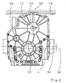
- the height of the axle 4 is determined by the Radius 42 of the rail wheel 44.
- the rail level is 46 designated.
- the center distance 48 between the input shaft and the pinion shaft is for transmitting a predetermined Torque required for a given ratio and can not be reduced any further.
- Space 50 and the vertical distance 52 between the axle 4 and the axis of rotation 54 of the input shaft. 2 is at the axle drive according to the invention by the amount of Misalignment 56 smaller.
- the bevel pinion shaft is around the Axial offset 56 with respect to the axis of rotation of the output side Bevel gear 40 offset downwards.
- the bevel pinion 38 and the output side bevel gear 40 are hypoid teeth and have a plus-axis offset.
- the axis of rotation 54 of the input shaft 2 has with respect to the axis of rotation 62 of the pinion shaft 32nd in addition to the vertical center distance component also a horizontal Axial distance component on, so it is obliquely above arranged.
- the height of the vehicle floor 48 is on the one hand by reduces the misalignment 56.
- the railcar floor in the area of the highest point of the gear housing 10 provided with a recess 68, in which the Transmission housing 10 projects from below.
- the geometry of the Recess is minimized and adapted to the spur gear 18.
Landscapes
- Engineering & Computer Science (AREA)
- Mechanical Engineering (AREA)
- General Engineering & Computer Science (AREA)
- Transportation (AREA)
- Gear Transmission (AREA)
Abstract
Description
Darin zeigen:
- Fig. 1
- eine Schnitt-Darstellung eines erfindungsgemäßen Triebwagen-Achsgetriebes und
- Fig. 2
- eine Seiten-Ansicht eines erfindungsgemäßen Triebwagen-Achsgetriebes.
- 2
- Eingangswelle
- 4
- Radsatzachse
- 6
- Lager
- 8
- Lager
- 10
- Stutzen
- 12
- Getriebegehäuse
- 14
- Flansch
- 16
- Stirnrad
- 18
- Stirnrad
- 20
- Schiebemuffe
- 22
- Schalteinrichtung
- 24
- Außenverzahnung
- 26
- Innenverzahnung
- 28
- Innenverzahnung
- 30
- Stirnrad
- 32
- Kegelritzelwelle
- 34
- Lager
- 36
- Lager
- 38
- Kegelritzel
- 40
- Kegelrad
- 42
- Radius
- 44
- Schienenrad
- 46
- Schienenebene
- 48
- Achsabstand
- 50
- Bauraum
- 52
- Achsabstand
- 54
- Drehachse
- 56
- Achsversatz
- 58
- Deckel
- 60
- Auge
- 62
- Drehachse
- 64
- Drehachse
- 66
- Drehachse
Claims (6)
- Triebwagen-Achsgetriebe mit einer eingangsseitigen Stirnradstufe und einer abtriebsseitigen Kegelradstufe, wobei ein erstes Stirnrad (16) der Stirnradstufe von einer koaxialen Eingangswelle (2) drehantreibbar in einem Getriebegehäuse (12) gelagert ist und sich in ständigem Zahneingriff mit einem zweiten Stirnrad (30) der Stirnradstufe befindet, welches auf einer Kegelritzelwelle (32) angeordnet ist, deren Kegelritzel (38) in Zahneingriff mit einem auf einer Radsatzachse (4) angeordneten, abtriebsseitigen Kegelrad (40) ist, wobei die Eingangswelle (2) und die Kegelritzelwelle (32) zumindest eine vertikale Achsabstandskomponente (48) aufweisen, und die Drehachse (54) der Eingangswelle (2) sich im Winkel zur und in einem vertikalen Abstand (52) oberhalb der Radsatzachse (4) erstreckt, dadurch gekennzeichnet, dass das Kegelritzel (38) gegenüber dem abtriebsseitigen Kegelrad (40) einen Achsversatz (56) nach unten aufweist, um den vertikalen Abstand (52) zwischen der Radsatzachse (4) und der Drehachse (54) der Eingangswelle (2) zu verringern.
- Triebwagen-Achsgetriebe nach Anspruch 1, dadurch gekennzeichnet, dass das Kegelritzel (38) und das abtriebsseitige Kegelrad (40) hypoidverzahnt sind und einen Plus-Achsversatz aufweisen.
- Triebwagen-Achsgetriebe nach Anspruch 1 oder 2, dadurch gekennzeichnet, dass die Eingangswelle (2) und die Kegelritzelwelle (32) neben der vertikalen Achsabstandskomponente auch eine horizontale Achsabstandskomponente aufweisen.
- Triebwagen mit einem Triebwagen-Achsgetriebe nach einem der Ansprüche 1 bis 3, welches unterhalb eines Triebwagen-Bodens (48) angeordnet ist.
- Triebwagen nach Anspruch 4, dadurch gekennzeichnet, dass der Triebwagen-Boden (48) im Bereich der höchsten Stelle des Getriebegehäuses (12) eine Ausnehmung (68) aufweist, in die das Getriebegehäuse (12) von unten hineinragt.
- Triebwagen nach Anspruch 4 oder 5, dadurch gekennzeichnet, dass das Achsgetriebe so zwischen einem linken und rechten Rad auf der Radsatzachse (4) angeordnet ist, dass die Eingangswelle (2) des Achsgetriebes im Bereich der Fahrzeugmitte liegt.
Priority Applications (1)
| Application Number | Priority Date | Filing Date | Title |
|---|---|---|---|
| EP20030025145 EP1557587B1 (de) | 2004-01-13 | 2004-01-13 | Triebwagen-Achsgetriebe |
Applications Claiming Priority (1)
| Application Number | Priority Date | Filing Date | Title |
|---|---|---|---|
| EP20030025145 EP1557587B1 (de) | 2004-01-13 | 2004-01-13 | Triebwagen-Achsgetriebe |
Publications (3)
| Publication Number | Publication Date |
|---|---|
| EP1557587A2 true EP1557587A2 (de) | 2005-07-27 |
| EP1557587A3 EP1557587A3 (de) | 2007-01-17 |
| EP1557587B1 EP1557587B1 (de) | 2010-10-13 |
Family
ID=34626373
Family Applications (1)
| Application Number | Title | Priority Date | Filing Date |
|---|---|---|---|
| EP20030025145 Expired - Lifetime EP1557587B1 (de) | 2004-01-13 | 2004-01-13 | Triebwagen-Achsgetriebe |
Country Status (1)
| Country | Link |
|---|---|
| EP (1) | EP1557587B1 (de) |
Cited By (2)
| Publication number | Priority date | Publication date | Assignee | Title |
|---|---|---|---|---|
| EP2108583A1 (de) * | 2008-04-10 | 2009-10-14 | Reintjes GmbH | Schiffsgetriebe mit Drehrichtungswechsel |
| DE102013222086A1 (de) | 2013-10-30 | 2015-04-30 | Zf Friedrichshafen Ag | Antriebsstrang für ein Schienenfahrzeug |
Family Cites Families (6)
| Publication number | Priority date | Publication date | Assignee | Title |
|---|---|---|---|---|
| US2589844A (en) * | 1948-04-23 | 1952-03-18 | Moore Irving | Change-speed gearing multiple drive transmission |
| DE903094C (de) * | 1951-10-07 | 1954-02-01 | Kloeckner Humboldt Deutz Ag | Achsantrieb fuer Schienenfahrzeuge mit zwei Treibachsen und einer im Fahrzeugrahmen fest gelagerten Antriebsanlage, die aus einer Brennkraftmaschine und zumindest einem Geschwindigkeits-Wechselgetriebe besteht |
| DE928232C (de) * | 1952-08-30 | 1955-05-26 | Kloeckner Humboldt Deutz Ag | Einzelantrieb der Radsaetze von Schienenfahrzeugdrehgestellen |
| GB1438620A (en) * | 1973-05-22 | 1976-06-09 | Hurth Verwaltungs Gmbh | Driving arrangement for the driven axles of rail vehicles |
| US4148262A (en) * | 1973-05-22 | 1979-04-10 | Carl Hurth Maschinen-Und Zahnradfabrik | Railway vehicle drive |
| DE19827580A1 (de) * | 1998-06-20 | 1999-12-23 | Zahnradfabrik Friedrichshafen | Antrieb für einen Triebwagen |
-
2004
- 2004-01-13 EP EP20030025145 patent/EP1557587B1/de not_active Expired - Lifetime
Cited By (2)
| Publication number | Priority date | Publication date | Assignee | Title |
|---|---|---|---|---|
| EP2108583A1 (de) * | 2008-04-10 | 2009-10-14 | Reintjes GmbH | Schiffsgetriebe mit Drehrichtungswechsel |
| DE102013222086A1 (de) | 2013-10-30 | 2015-04-30 | Zf Friedrichshafen Ag | Antriebsstrang für ein Schienenfahrzeug |
Also Published As
| Publication number | Publication date |
|---|---|
| EP1557587A3 (de) | 2007-01-17 |
| EP1557587B1 (de) | 2010-10-13 |
Similar Documents
| Publication | Publication Date | Title |
|---|---|---|
| DE19826067B4 (de) | Getriebe für ein lenkbares Antriebsrad eines Flurförderfahrzeugs | |
| EP1926624A2 (de) | Antriebssystem für den einzelantrieb der beiden antriebsräder eines antriebsräderpaares | |
| EP0507137B1 (de) | Lenkbarer Radantrieb | |
| WO2015014449A1 (de) | Antriebsstrang eines kraftfahrzeugs | |
| EP3165433B1 (de) | Rangierantrieb für einen anhänger | |
| DE69405202T2 (de) | Untersetzungsgetriebe und Kraftübertragung mit zwei Gangstufen für ein Kraftfahrzeug | |
| DE102011087163A1 (de) | Getriebe eines Kraftfahrzeuges mit Nebenantrieb | |
| EP2669155B1 (de) | Anhänger-Rangierantrieb mit Getriebe mit nicht paralleler Achsanordnung | |
| DE10065107C2 (de) | Winkelgetriebe mit Leistungsverzweigung | |
| DE19633316C2 (de) | Einrad-Trieb- und Lenkwerk für Flurförderfahrzeuge | |
| DE10353927A1 (de) | Achsen-Anordnung | |
| DE102013222086A1 (de) | Antriebsstrang für ein Schienenfahrzeug | |
| DE10252192A1 (de) | Triebwagen-Achsgetriebe | |
| EP1557587B1 (de) | Triebwagen-Achsgetriebe | |
| DE102018219521A1 (de) | Elektromotorisch angetriebene Starrachse für Fahrzeuge, insbesondere Nutzfahrzeuge, und Verfahren zu deren Betrieb, Computerprogrammprodukt, Steuerungs- und/oder Regelungsvorrichtung und Kraftfahrzeug | |
| EP1199237B1 (de) | Getriebe für Schienenfahrzeuge | |
| DE102004003645A1 (de) | Portaltrieb für eine Portalachse | |
| DE3000298A1 (de) | Antriebseinheit | |
| DE102006046580A1 (de) | Mehrstufiges Untersetzungsgetriebe | |
| DE10229862A1 (de) | Normal ineinandergreifender Universaldifferentialantrieb | |
| DE102013210344B4 (de) | Antriebsstrang für ein Schienenfahrzeug | |
| DE102006046579A1 (de) | Mehrstufiges Untersetzungsgetriebe | |
| EP1638800B1 (de) | Portalachse | |
| DE102004054917A1 (de) | Getriebe für ein Schienenfahrzeug, insbesondere ein Niederflurfahrzeug, und damit ausgerüstetes Schienenfahrzeug | |
| DE102004003632A1 (de) | Portaltrieb |
Legal Events
| Date | Code | Title | Description |
|---|---|---|---|
| PUAI | Public reference made under article 153(3) epc to a published international application that has entered the european phase |
Free format text: ORIGINAL CODE: 0009012 |
|
| AK | Designated contracting states |
Kind code of ref document: A2 Designated state(s): AT BE BG CH CY CZ DK EE ES FI FR GB GR HU IE IT LI LU MC NL PT RO SE SI SK TR |
|
| AX | Request for extension of the european patent |
Extension state: AL LT LV MK |
|
| PUAL | Search report despatched |
Free format text: ORIGINAL CODE: 0009013 |
|
| AK | Designated contracting states |
Kind code of ref document: A3 Designated state(s): AT BE BG CH CY CZ DK EE ES FI FR GB GR HU IE IT LI LU MC NL PT RO SE SI SK TR |
|
| AX | Request for extension of the european patent |
Extension state: AL LT LV MK |
|
| 17P | Request for examination filed |
Effective date: 20070618 |
|
| AKX | Designation fees paid |
Designated state(s): BE CZ GB IT |
|
| 17Q | First examination report despatched |
Effective date: 20071023 |
|
| GRAP | Despatch of communication of intention to grant a patent |
Free format text: ORIGINAL CODE: EPIDOSNIGR1 |
|
| GRAS | Grant fee paid |
Free format text: ORIGINAL CODE: EPIDOSNIGR3 |
|
| GRAA | (expected) grant |
Free format text: ORIGINAL CODE: 0009210 |
|
| AK | Designated contracting states |
Kind code of ref document: B1 Designated state(s): BE CZ GB IT |
|
| REG | Reference to a national code |
Ref country code: GB Ref legal event code: FG4D Free format text: NOT ENGLISH |
|
| PLBE | No opposition filed within time limit |
Free format text: ORIGINAL CODE: 0009261 |
|
| STAA | Information on the status of an ep patent application or granted ep patent |
Free format text: STATUS: NO OPPOSITION FILED WITHIN TIME LIMIT |
|
| 26N | No opposition filed |
Effective date: 20110714 |
|
| PGFP | Annual fee paid to national office [announced via postgrant information from national office to epo] |
Ref country code: IT Payment date: 20190121 Year of fee payment: 16 |
|
| PG25 | Lapsed in a contracting state [announced via postgrant information from national office to epo] |
Ref country code: IT Free format text: LAPSE BECAUSE OF NON-PAYMENT OF DUE FEES Effective date: 20200113 |
|
| PGFP | Annual fee paid to national office [announced via postgrant information from national office to epo] |
Ref country code: GB Payment date: 20221124 Year of fee payment: 20 Ref country code: CZ Payment date: 20221215 Year of fee payment: 20 |
|
| PGFP | Annual fee paid to national office [announced via postgrant information from national office to epo] |
Ref country code: BE Payment date: 20221216 Year of fee payment: 20 |
|
| P01 | Opt-out of the competence of the unified patent court (upc) registered |
Effective date: 20230528 |
|
| REG | Reference to a national code |
Ref country code: BE Ref legal event code: MK Effective date: 20240113 |
|
| PG25 | Lapsed in a contracting state [announced via postgrant information from national office to epo] |
Ref country code: CZ Free format text: LAPSE BECAUSE OF EXPIRATION OF PROTECTION Effective date: 20240113 |
|
| REG | Reference to a national code |
Ref country code: GB Ref legal event code: PE20 Expiry date: 20240112 |
|
| PG25 | Lapsed in a contracting state [announced via postgrant information from national office to epo] |
Ref country code: GB Free format text: LAPSE BECAUSE OF EXPIRATION OF PROTECTION Effective date: 20240112 |