EP1559512A2 - Fluid-operated power tool - Google Patents
Fluid-operated power tool Download PDFInfo
- Publication number
- EP1559512A2 EP1559512A2 EP05250537A EP05250537A EP1559512A2 EP 1559512 A2 EP1559512 A2 EP 1559512A2 EP 05250537 A EP05250537 A EP 05250537A EP 05250537 A EP05250537 A EP 05250537A EP 1559512 A2 EP1559512 A2 EP 1559512A2
- Authority
- EP
- European Patent Office
- Prior art keywords
- another
- housing
- housings
- fluid
- power tool
- Prior art date
- Legal status (The legal status is an assumption and is not a legal conclusion. Google has not performed a legal analysis and makes no representation as to the accuracy of the status listed.)
- Withdrawn
Links
- 230000007246 mechanism Effects 0.000 claims abstract description 20
- 230000015572 biosynthetic process Effects 0.000 claims description 15
- 238000005755 formation reaction Methods 0.000 claims description 15
- 230000037431 insertion Effects 0.000 claims 1
- 238000003780 insertion Methods 0.000 claims 1
- 238000010276 construction Methods 0.000 description 3
- 239000012530 fluid Substances 0.000 description 3
- 238000000034 method Methods 0.000 description 2
- CYJRNFFLTBEQSQ-UHFFFAOYSA-N 8-(3-methyl-1-benzothiophen-5-yl)-N-(4-methylsulfonylpyridin-3-yl)quinoxalin-6-amine Chemical compound CS(=O)(=O)C1=C(C=NC=C1)NC=1C=C2N=CC=NC2=C(C=1)C=1C=CC2=C(C(=CS2)C)C=1 CYJRNFFLTBEQSQ-UHFFFAOYSA-N 0.000 description 1
- 239000004519 grease Substances 0.000 description 1
- 239000000463 material Substances 0.000 description 1
- 238000012986 modification Methods 0.000 description 1
- 230000004048 modification Effects 0.000 description 1
- 238000011084 recovery Methods 0.000 description 1
- 125000006850 spacer group Chemical group 0.000 description 1
Images


Classifications
-
- B—PERFORMING OPERATIONS; TRANSPORTING
- B25—HAND TOOLS; PORTABLE POWER-DRIVEN TOOLS; MANIPULATORS
- B25B—TOOLS OR BENCH DEVICES NOT OTHERWISE PROVIDED FOR, FOR FASTENING, CONNECTING, DISENGAGING OR HOLDING
- B25B21/00—Portable power-driven screw or nut setting or loosening tools; Attachments for drilling apparatus serving the same purpose
- B25B21/004—Portable power-driven screw or nut setting or loosening tools; Attachments for drilling apparatus serving the same purpose of the ratchet type
- B25B21/005—Portable power-driven screw or nut setting or loosening tools; Attachments for drilling apparatus serving the same purpose of the ratchet type driven by a radially acting hydraulic or pneumatic piston
-
- B—PERFORMING OPERATIONS; TRANSPORTING
- B25—HAND TOOLS; PORTABLE POWER-DRIVEN TOOLS; MANIPULATORS
- B25B—TOOLS OR BENCH DEVICES NOT OTHERWISE PROVIDED FOR, FOR FASTENING, CONNECTING, DISENGAGING OR HOLDING
- B25B21/00—Portable power-driven screw or nut setting or loosening tools; Attachments for drilling apparatus serving the same purpose
-
- B—PERFORMING OPERATIONS; TRANSPORTING
- B25—HAND TOOLS; PORTABLE POWER-DRIVEN TOOLS; MANIPULATORS
- B25B—TOOLS OR BENCH DEVICES NOT OTHERWISE PROVIDED FOR, FOR FASTENING, CONNECTING, DISENGAGING OR HOLDING
- B25B13/00—Spanners; Wrenches
- B25B13/46—Spanners; Wrenches of the ratchet type, for providing a free return stroke of the handle
-
- B—PERFORMING OPERATIONS; TRANSPORTING
- B25—HAND TOOLS; PORTABLE POWER-DRIVEN TOOLS; MANIPULATORS
- B25F—COMBINATION OR MULTI-PURPOSE TOOLS NOT OTHERWISE PROVIDED FOR; DETAILS OR COMPONENTS OF PORTABLE POWER-DRIVEN TOOLS NOT PARTICULARLY RELATED TO THE OPERATIONS PERFORMED AND NOT OTHERWISE PROVIDED FOR
- B25F5/00—Details or components of portable power-driven tools not particularly related to the operations performed and not otherwise provided for
Definitions
- the present invention generally relates to fluid-operated power tools. More particularly, it relates to power tools with interchangeable, lever-drive mechanisms for a variety of bolting applications.
- Fluid operated power tools of this general type are known in the art. Some of such tools are disclosed in U.S. patents nos. 6,260,444 and 6,427,559. In such tools lever-drive mechanisms can be interchanged for different bolting operations. Limited clearance, fluid-operated tools have an attachable hex link which contains a lever-drive mechanism and forms one housing, while another motor housing contains a fluid-operated drive unit. In all such tools the exchangeable link of one housing is connected to the other motor housing via screws and pins after the housings are assembled with one another. As a result, such screws and pins can loosen during the operation and end up inside a turbine, a compressor, or another equipment if they fall off during assembly.
- a fluid-operated power tool comprising drive means including a fluid-operator cylinder-piston unit; a first housing accommodating the drive means; a lever-drive mechanism connected with the drive means and powered by the latter and also engageable with a fastener for bolting applications; a second housing accommodating the lever-drive mechanism, wherein the two housings are interconnected so as to turn a fastener when the lever-drive mechanism is connected to the fastener and powered by the drive means; and connecting means for releasably connecting the housings with one another so that the housings are connectable with one another and disconnectable with one another, the connecting means including a female portion provided on one of the housings and a male portion provided on the other of the housings and engageable with the female portion for operably connecting the first housing and the second housing with one another without subsequently requiring additional pins, screws and other means to provide a connection between the housings.
- the connecting means is formed to counteract forces created by the drive means during operation so as to counteract a tendency of the first housing accommodating the cylinder-piston unit to move along its axis away from the second housing and also to counteract a tendency of the first housing accommodating the cylinder-piston unit to move transversely to the axis.
- the fluid-operated tool When the fluid-operated tool is designed in accordance with these features, it solves a very important problem. There are two forces created by the cylinder-piston unit that push the lever/drive mechanism.
- the housing which accommodates the cylinder-piston unit wants to move back away from the housing which accommodates the lever-drive mechanism along the axis of the cylinder-piston unit.
- the cylinder-piston unit wants to twist under power relative to the housing accommodating the lever-drive mechanism. This means that the cylinder housing has to be prevented from sliding not only backwards, but also upwards.
- the fluid-operated power tool When the fluid-operated power tool is designed in accordance with this new inventive feature, it solves this problem by stopping the housing accommodating the cylinder-piston unit from sliding backwards and upwards.
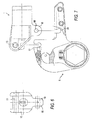
- Figure 1 is a view showing a fluid-operated power tool in accordance with the present invention in an assembled condition
- Figure 2 is a view showing a section of the fluid-operated power tool of Figure 1, taken along the line 2-2;
- Figure 3 is a view showing a lever-drive housing of the inventive fluid-operated power tool
- Figure 4 is a view of the lever-drive housing of Figure 3, as viewed in direction of the arrows 4-4;
- Figure 5 is a view showing a section of the lever-drive mechanism of Figure 3, taken along the line 5-5;
- Figure 6 is a view showing details of fixing pins associated with the housing of the fluid-operated power tool of the present invention, which accommodates a cylinder-piston unit;
- Figure 7 is a view illustrating a process of assembling of the housings of the fluid-operated power tool in accordance with the present invention.
- a fluid-operated power tool in accordance with the present invention has a first housing which is identified with reference numeral 1 and accommodates a drive means formed, for example, as a fluid-operated cylinder-piston unit.
- the fluid-operated cylinder-piston unit includes a cylinder 2 and a piston 3 provided with a piston rod 4 and displaceable in the cylinder 2.
- the fluid-operated power tool further has a second housing which is identified with reference numeral 5 and accommodates a lever-drive mechanism.
- the lever-drive mechanism includes a lever 6 displaceable by the piston rod 4 and carrying a pawl 7 which engages with teeth of a ratchet 8 arranged turnably in the lever 6.
- the lever 6 is movable between side plates 9, which together with a spacer 10 form the housing 5.
- a power fluid is supplied into the cylinder 2, for example to the right side of the piston 3, and displaces the piston 3 with the piston rod 4 to the left, the lever 6 is turned by the piston rod and the pawl 7 turns the ratchet 8, so that a corresponding element, for example a socket, a projection, etc. cooperating with the ratchet engages a fastener and turns the fastener.
- the fluid-operated power tool is provided with connecting means which connects the housings 1 and 5 with one another, so that during an assembly of the housings 1 and 5 with one another, or after the assembly, no additional pins, screws or other parts have to be inserted into the housings to form the connection.
- the connecting means include two connection units which are preferably spaced from one another in a substantially vertical direction and in a substantially horizontal direction, in the view of Figure 1. In other words they are spaced from one another preferably in the direction of an axis Al of the cylinder-piston unit and also in the direction which is transverse to the axis.
- the first connection unit of the connecting means includes a pin 13 which extends through through-going openings 14 in side portions 15 of the housing 1 and is fixed in the openings 14 by retaining rings 16.
- the first connection unit further includes upwardly open slots 17 provided in side plates 9 of the housing 5, into which the pin 13 is insertable.
- the slots 17 of the side plates 9 of the housing 5 form a female formation, while the pin 13 fixed in the side portions 15 of the housing 1 forms a male formation which is insertable in the female formation.
- the second connection unit of the connecting means includes a downwardly extending loop-shaped projection 18 provided in the cylinder 2 and holding a pin 19, and also slots 20 provided in the side plates 9 of the housing 5.
- the slots 20 in the side plates 9 of the housing 5 form a female formation, while the pin 19 in the cylinder 2 of the housing 1 forms a male formation which is insertable in the female formation.
- connection units are spaced from one another in two transverse directions, for example in the direction of the axis Al and in the direction which is transverse to the axis Al.
- the same is true for the male and female formations.
- the male formations 13 and 19 are spaced from one another in two mutually transverse directions, and the female formations 17 and 20 are also spaced from one another in two mutually transverse directions.
- the housing 5 In order to assemble the housings 1 and 5 with one another, the housing 5 is moved toward the housing 1, so that the pin 13 is inserted into the slots 17 and the pin 19 is inserted into the slots 20.
- a locking mechanism is provided for locking the housings 1 and 5 with one another in the assembled condition.
- the locking mechanism includes a lever 21 which is turnable about an axis 22.
- the lever 21 has one arm 23 having for example a cam-shaped end, and another arm 24, so that the arms are located at opposite sides of the axis 22.
- a spring 25 pulls the' arm 24 of the lever 21 upwardly in Figure 1, so that the cam-shaped end of the arm 23 abuts against the pin 13 and prevents disengagement of the pin 13 from the slots 17.
- each of the slots 17 and 20 is formed so that it has one part extending in one direction, in particular in a vertical direction in Figure 3 as identified with reference numerals 17' and 20', and another part which is offset in direction of the axis Al from the first mentioned part 17' and 20' as identified with reference numerals 17" and 20".
- the slots 17 and 20 can have substantially the shape of a letter J.
- the housing 1 can not move relative to the housing 5 in the axial direction of the axis Al away from the housing 5 because the pins 13 and 19 abut against a side surface 26 of the slots 17 and 20. At the same time, the housing 1 can not move relative to the housing 5 transversely to the axis Al upwardly, because the pins 13 and 19 abut against an upper surface 27 of the parts 17" and 20" of the slots 17 and 20.
Landscapes
- Engineering & Computer Science (AREA)
- Mechanical Engineering (AREA)
- Actuator (AREA)
- Fluid-Pressure Circuits (AREA)
- Shearing Machines (AREA)
- Gripping On Spindles (AREA)
- Portable Power Tools In General (AREA)
- Accommodation For Nursing Or Treatment Tables (AREA)
Abstract
Description
Claims (6)
- A fluid-operated power tool, comprising drive means including a fluid-operated cylinder-piston unit (2, 3); a first housing (1) accommodating the drive means; a lever-drive mechanism (6, 7) connected with the drive means and powered by the latter and also engageable with a fastener for bolting applications; a second housing (5) accommodating the lever-drive mechanism (6, 7), the housings (1, 5) being interconnected so as to turn a fastener when the lever-drive mechanism is connected to the fastener and powered by the drive means; and connecting means (13, 17, 19, 20) for releasably connecting the housings (1, 5) with one another so that the housings are connectable with one another and disconnectable from one another, characterised in that the connecting means include a female portion (17, 20) provided in one of the housings and a male portion (13, 19) provided in the other of the housings and engageable with the female portion for operably connecting the first housing (1) and the second housing (5) with one another without subsequently requiring additional pins, screws and other means to provide a connection between the housings.
- A fluid-operated power tool according to claim 1, further comprising locking means (21-25) which, subsequently to insertion of the male portion (13) into the female portion (17), automatically lock the housings (1, 5) with one another, the locking means (21-25) being actuatable by a user so as to unlock the housings from one another and to allow withdrawal of the male portion (13) from the female portion (19) and therefore disconnection of the housings (1, 5) from one another.
- A fluid-operated power tool according to claim 1 or 2, wherein the female portion has at least two female formations (17, 20) provided in the one housing (5) and spaced from one another, and the male portion has two male formations (13, 19) provided in the other housing (1) and spaced from one another, so that each of the male formations (13, 19) engages in a corresponding one of the female formations (17, 20).
- A fluid-operated power tool according to claim 3, wherein the female formations (17, 20) are spaced from one another in directions which are substantially transverse to one another, the male formations (13, 19) being also spaced from one another in said directions which are substantially transverse to one another.
- A fluid-operated power tool according to any preceding claim, wherein the connecting means (13, 17, 19, 20) are formed so that they counteract forces created by the drive means during operation so as to counteract a tendency of the first housing (1) accommodating the cylinder-piston unit (2, 3) to displace along its axis (A1) away from the second housing (5) and also to counteract a tendency of the first housing (1) accommodating the cylinder-piston unit to displace transversely to the axis (A1).
- A fluid-operated power tool according to claim 5, wherein the female portion (17, 20) includes one part (17', 20') extending in one direction, and another part (17", 20") which is offset relative to the one part in a direction which is transverse to the one direction.
Applications Claiming Priority (2)
| Application Number | Priority Date | Filing Date | Title |
|---|---|---|---|
| US770209 | 1996-12-19 | ||
| US10/770,209 US6925911B1 (en) | 2004-02-02 | 2004-02-02 | Fluid-operated power tool |
Publications (2)
| Publication Number | Publication Date |
|---|---|
| EP1559512A2 true EP1559512A2 (en) | 2005-08-03 |
| EP1559512A3 EP1559512A3 (en) | 2006-04-05 |
Family
ID=34654400
Family Applications (1)
| Application Number | Title | Priority Date | Filing Date |
|---|---|---|---|
| EP05250537A Withdrawn EP1559512A3 (en) | 2004-02-02 | 2005-02-01 | Fluid-operated power tool |
Country Status (10)
| Country | Link |
|---|---|
| US (1) | US6925911B1 (en) |
| EP (1) | EP1559512A3 (en) |
| JP (1) | JP2005212095A (en) |
| KR (1) | KR20050078626A (en) |
| CN (1) | CN1651194A (en) |
| AU (1) | AU2004202833B2 (en) |
| BR (1) | BRPI0405473A (en) |
| MX (1) | MXPA04009495A (en) |
| TW (1) | TWI247650B (en) |
| ZA (1) | ZA200405026B (en) |
Cited By (2)
| Publication number | Priority date | Publication date | Assignee | Title |
|---|---|---|---|---|
| US7497147B2 (en) | 2006-09-12 | 2009-03-03 | Unex Corporation | Torque tool for tightening or loosening connections, and method of tightening or loosening the same |
| GB2453329A (en) * | 2007-10-01 | 2009-04-08 | Unex Corp | Torque tool for tightening or loosening connections |
Families Citing this family (7)
| Publication number | Priority date | Publication date | Assignee | Title |
|---|---|---|---|---|
| US7261018B2 (en) * | 2005-11-14 | 2007-08-28 | Jetyd Corp. | Power tool |
| EA014978B1 (en) * | 2007-11-20 | 2011-04-29 | Юнекс Корпорейшн | Torque tool and method of tightening or loosening connections using the same |
| US20100050818A1 (en) * | 2008-08-26 | 2010-03-04 | Rogers David H | Adjustable ratchet system |
| US9550282B2 (en) * | 2014-04-22 | 2017-01-24 | John D. Davis | Compact hydraulic torque wrench cartridge |
| DE102015006564A1 (en) * | 2015-05-20 | 2016-11-24 | Frank Hohmann | Torque Wrench System |
| ES2927807T3 (en) | 2015-10-05 | 2022-11-11 | Hytorc Division Unex Corp | Apparatus for tightening threaded fasteners |
| USD1042067S1 (en) * | 2023-02-28 | 2024-09-17 | Primesource Consulting Llc | Limited clearance tool |
Family Cites Families (5)
| Publication number | Priority date | Publication date | Assignee | Title |
|---|---|---|---|---|
| US523238A (en) * | 1894-07-17 | Joint and bearing | ||
| DE3719893A1 (en) * | 1987-06-13 | 1988-12-29 | Wagner Paul Heinz | HYDRAULIC SCREWDRIVER |
| USRE33951E (en) * | 1987-09-29 | 1992-06-09 | Fluid operated wrench | |
| US6260444B1 (en) | 1999-06-23 | 2001-07-17 | John K. Junkers | Power tool |
| US20020121161A1 (en) * | 2001-03-05 | 2002-09-05 | Peter Koppenhoefer | Fluid operated tool for tightening and loosening threaded connectors |
-
2004
- 2004-02-02 US US10/770,209 patent/US6925911B1/en not_active Expired - Lifetime
- 2004-06-24 ZA ZA200405026A patent/ZA200405026B/en unknown
- 2004-06-24 AU AU2004202833A patent/AU2004202833B2/en not_active Ceased
- 2004-06-29 TW TW093118946A patent/TWI247650B/en active
- 2004-07-08 KR KR1020040052957A patent/KR20050078626A/en not_active Abandoned
- 2004-07-23 CN CNA2004100586137A patent/CN1651194A/en active Pending
- 2004-09-29 MX MXPA04009495A patent/MXPA04009495A/en unknown
- 2004-12-03 BR BR0405473-3A patent/BRPI0405473A/en not_active IP Right Cessation
-
2005
- 2005-01-31 JP JP2005022613A patent/JP2005212095A/en not_active Abandoned
- 2005-02-01 EP EP05250537A patent/EP1559512A3/en not_active Withdrawn
Cited By (5)
| Publication number | Priority date | Publication date | Assignee | Title |
|---|---|---|---|---|
| US7497147B2 (en) | 2006-09-12 | 2009-03-03 | Unex Corporation | Torque tool for tightening or loosening connections, and method of tightening or loosening the same |
| DE102007044251B4 (en) * | 2006-09-12 | 2012-03-22 | Unex Corp. | Torque tool and method for tightening or loosening connections |
| DK178776B1 (en) * | 2006-09-12 | 2017-01-16 | Unex Corp | Tightening torque tool for tightening or loosening connections or method for tightening or loosening same |
| GB2453329A (en) * | 2007-10-01 | 2009-04-08 | Unex Corp | Torque tool for tightening or loosening connections |
| GB2453329B (en) * | 2007-10-01 | 2012-07-25 | Unex Corp | Torque tool for tightening or loosening connections and method of tightening or loosening the same |
Also Published As
| Publication number | Publication date |
|---|---|
| TWI247650B (en) | 2006-01-21 |
| TW200526376A (en) | 2005-08-16 |
| MXPA04009495A (en) | 2005-08-04 |
| KR20050078626A (en) | 2005-08-05 |
| CN1651194A (en) | 2005-08-10 |
| US20050166716A1 (en) | 2005-08-04 |
| US6925911B1 (en) | 2005-08-09 |
| AU2004202833B2 (en) | 2006-01-12 |
| EP1559512A3 (en) | 2006-04-05 |
| ZA200405026B (en) | 2005-03-10 |
| AU2004202833A1 (en) | 2005-08-18 |
| JP2005212095A (en) | 2005-08-11 |
| BRPI0405473A (en) | 2005-11-01 |
Similar Documents
| Publication | Publication Date | Title |
|---|---|---|
| US4794825A (en) | Hydraulic power wrench | |
| EP2055435B1 (en) | Fluid-operated torque wrench for and method of tightening or loosening fasteners | |
| EP1559512A2 (en) | Fluid-operated power tool | |
| US20040067126A1 (en) | Coupling assembly | |
| US20020121161A1 (en) | Fluid operated tool for tightening and loosening threaded connectors | |
| CA2456020C (en) | Locking swivel apparatus with a supplemental internal locking mechanism | |
| US20040144567A1 (en) | Locking swivel apparatus with replaceable internal gear members | |
| US20100050402A1 (en) | locking device | |
| HK1075431A (en) | Fluid-operated power tool | |
| CA2620557A1 (en) | Actuator device | |
| US9890600B1 (en) | Power tongs with supporting struts | |
| HUE032842T2 (en) | System for making circular holes | |
| US9828814B1 (en) | Power tongs with shaft retainers | |
| EP1229211A2 (en) | Breech lock wireline connector | |
| JP2007260804A (en) | Open type hydraulic wrench | |
| AU641502B2 (en) | Fluid-operated wrench | |
| CN114809154A (en) | Quick connector | |
| US10087691B1 (en) | Power tongs | |
| JP2023127271A (en) | double wrench | |
| CN221443204U (en) | Quick-dismantling chain | |
| AU650231B2 (en) | Locking socket wrench drive device | |
| CA3095421A1 (en) | Process and apparatus for applying torque | |
| CN2498320Y (en) | Slipway style back-up wrench for drilling and maintaining | |
| JPH0639362U (en) | Impact socket wrench |
Legal Events
| Date | Code | Title | Description |
|---|---|---|---|
| PUAI | Public reference made under article 153(3) epc to a published international application that has entered the european phase |
Free format text: ORIGINAL CODE: 0009012 |
|
| 17P | Request for examination filed |
Effective date: 20050214 |
|
| AK | Designated contracting states |
Kind code of ref document: A2 Designated state(s): AT BE BG CH CY CZ DE DK EE ES FI FR GB GR HU IE IS IT LI LT LU MC NL PL PT RO SE SI SK TR |
|
| AX | Request for extension of the european patent |
Extension state: AL BA HR LV MK YU |
|
| REG | Reference to a national code |
Ref country code: HK Ref legal event code: DE Ref document number: 1075431 Country of ref document: HK |
|
| PUAL | Search report despatched |
Free format text: ORIGINAL CODE: 0009013 |
|
| AK | Designated contracting states |
Kind code of ref document: A3 Designated state(s): AT BE BG CH CY CZ DE DK EE ES FI FR GB GR HU IE IS IT LI LT LU MC NL PL PT RO SE SI SK TR |
|
| AX | Request for extension of the european patent |
Extension state: AL BA HR LV MK YU |
|
| AKX | Designation fees paid | ||
| REG | Reference to a national code |
Ref country code: DE Ref legal event code: 8566 |
|
| STAA | Information on the status of an ep patent application or granted ep patent |
Free format text: STATUS: THE APPLICATION IS DEEMED TO BE WITHDRAWN |
|
| 18D | Application deemed to be withdrawn |
Effective date: 20061006 |
|
| REG | Reference to a national code |
Ref country code: HK Ref legal event code: WD Ref document number: 1075431 Country of ref document: HK |