EP1561993A2 - LED lamps and method of cooling their LED - Google Patents
LED lamps and method of cooling their LED Download PDFInfo
- Publication number
- EP1561993A2 EP1561993A2 EP04105649A EP04105649A EP1561993A2 EP 1561993 A2 EP1561993 A2 EP 1561993A2 EP 04105649 A EP04105649 A EP 04105649A EP 04105649 A EP04105649 A EP 04105649A EP 1561993 A2 EP1561993 A2 EP 1561993A2
- Authority
- EP
- European Patent Office
- Prior art keywords
- air
- shell
- optical reflector
- heat sink
- fan
- Prior art date
- Legal status (The legal status is an assumption and is not a legal conclusion. Google has not performed a legal analysis and makes no representation as to the accuracy of the status listed.)
- Granted
Links
Images


Classifications
-
- F—MECHANICAL ENGINEERING; LIGHTING; HEATING; WEAPONS; BLASTING
- F21—LIGHTING
- F21V—FUNCTIONAL FEATURES OR DETAILS OF LIGHTING DEVICES OR SYSTEMS THEREOF; STRUCTURAL COMBINATIONS OF LIGHTING DEVICES WITH OTHER ARTICLES, NOT OTHERWISE PROVIDED FOR
- F21V29/00—Protecting lighting devices from thermal damage; Cooling or heating arrangements specially adapted for lighting devices or systems
- F21V29/50—Cooling arrangements
- F21V29/70—Cooling arrangements characterised by passive heat-dissipating elements, e.g. heat-sinks
- F21V29/74—Cooling arrangements characterised by passive heat-dissipating elements, e.g. heat-sinks with fins or blades
-
- F—MECHANICAL ENGINEERING; LIGHTING; HEATING; WEAPONS; BLASTING
- F21—LIGHTING
- F21K—NON-ELECTRIC LIGHT SOURCES USING LUMINESCENCE; LIGHT SOURCES USING ELECTROCHEMILUMINESCENCE; LIGHT SOURCES USING CHARGES OF COMBUSTIBLE MATERIAL; LIGHT SOURCES USING SEMICONDUCTOR DEVICES AS LIGHT-GENERATING ELEMENTS; LIGHT SOURCES NOT OTHERWISE PROVIDED FOR
- F21K9/00—Light sources using semiconductor devices as light-generating elements, e.g. using light-emitting diodes [LED] or lasers
- F21K9/20—Light sources comprising attachment means
- F21K9/23—Retrofit light sources for lighting devices with a single fitting for each light source, e.g. for substitution of incandescent lamps with bayonet or threaded fittings
- F21K9/233—Retrofit light sources for lighting devices with a single fitting for each light source, e.g. for substitution of incandescent lamps with bayonet or threaded fittings specially adapted for generating a spot light distribution, e.g. for substitution of reflector lamps
-
- F—MECHANICAL ENGINEERING; LIGHTING; HEATING; WEAPONS; BLASTING
- F21—LIGHTING
- F21S—NON-PORTABLE LIGHTING DEVICES; SYSTEMS THEREOF; VEHICLE LIGHTING DEVICES SPECIALLY ADAPTED FOR VEHICLE EXTERIORS
- F21S6/00—Lighting devices intended to be free-standing
- F21S6/002—Table lamps, e.g. for ambient lighting
- F21S6/003—Table lamps, e.g. for ambient lighting for task lighting, e.g. for reading or desk work, e.g. angle poise lamps
-
- F—MECHANICAL ENGINEERING; LIGHTING; HEATING; WEAPONS; BLASTING
- F21—LIGHTING
- F21S—NON-PORTABLE LIGHTING DEVICES; SYSTEMS THEREOF; VEHICLE LIGHTING DEVICES SPECIALLY ADAPTED FOR VEHICLE EXTERIORS
- F21S8/00—Lighting devices intended for fixed installation
- F21S8/02—Lighting devices intended for fixed installation of recess-mounted type, e.g. downlighters
- F21S8/026—Lighting devices intended for fixed installation of recess-mounted type, e.g. downlighters intended to be recessed in a ceiling or like overhead structure, e.g. suspended ceiling
-
- F—MECHANICAL ENGINEERING; LIGHTING; HEATING; WEAPONS; BLASTING
- F21—LIGHTING
- F21V—FUNCTIONAL FEATURES OR DETAILS OF LIGHTING DEVICES OR SYSTEMS THEREOF; STRUCTURAL COMBINATIONS OF LIGHTING DEVICES WITH OTHER ARTICLES, NOT OTHERWISE PROVIDED FOR
- F21V29/00—Protecting lighting devices from thermal damage; Cooling or heating arrangements specially adapted for lighting devices or systems
- F21V29/50—Cooling arrangements
- F21V29/60—Cooling arrangements characterised by the use of a forced flow of gas, e.g. air
- F21V29/67—Cooling arrangements characterised by the use of a forced flow of gas, e.g. air characterised by the arrangement of fans
-
- F—MECHANICAL ENGINEERING; LIGHTING; HEATING; WEAPONS; BLASTING
- F21—LIGHTING
- F21V—FUNCTIONAL FEATURES OR DETAILS OF LIGHTING DEVICES OR SYSTEMS THEREOF; STRUCTURAL COMBINATIONS OF LIGHTING DEVICES WITH OTHER ARTICLES, NOT OTHERWISE PROVIDED FOR
- F21V29/00—Protecting lighting devices from thermal damage; Cooling or heating arrangements specially adapted for lighting devices or systems
- F21V29/50—Cooling arrangements
- F21V29/60—Cooling arrangements characterised by the use of a forced flow of gas, e.g. air
- F21V29/67—Cooling arrangements characterised by the use of a forced flow of gas, e.g. air characterised by the arrangement of fans
- F21V29/673—Cooling arrangements characterised by the use of a forced flow of gas, e.g. air characterised by the arrangement of fans the fans being used for intake
-
- F—MECHANICAL ENGINEERING; LIGHTING; HEATING; WEAPONS; BLASTING
- F21—LIGHTING
- F21V—FUNCTIONAL FEATURES OR DETAILS OF LIGHTING DEVICES OR SYSTEMS THEREOF; STRUCTURAL COMBINATIONS OF LIGHTING DEVICES WITH OTHER ARTICLES, NOT OTHERWISE PROVIDED FOR
- F21V29/00—Protecting lighting devices from thermal damage; Cooling or heating arrangements specially adapted for lighting devices or systems
- F21V29/50—Cooling arrangements
- F21V29/70—Cooling arrangements characterised by passive heat-dissipating elements, e.g. heat-sinks
- F21V29/74—Cooling arrangements characterised by passive heat-dissipating elements, e.g. heat-sinks with fins or blades
- F21V29/75—Cooling arrangements characterised by passive heat-dissipating elements, e.g. heat-sinks with fins or blades with fins or blades having different shapes, thicknesses or spacing
-
- F—MECHANICAL ENGINEERING; LIGHTING; HEATING; WEAPONS; BLASTING
- F21—LIGHTING
- F21V—FUNCTIONAL FEATURES OR DETAILS OF LIGHTING DEVICES OR SYSTEMS THEREOF; STRUCTURAL COMBINATIONS OF LIGHTING DEVICES WITH OTHER ARTICLES, NOT OTHERWISE PROVIDED FOR
- F21V29/00—Protecting lighting devices from thermal damage; Cooling or heating arrangements specially adapted for lighting devices or systems
- F21V29/50—Cooling arrangements
- F21V29/70—Cooling arrangements characterised by passive heat-dissipating elements, e.g. heat-sinks
- F21V29/74—Cooling arrangements characterised by passive heat-dissipating elements, e.g. heat-sinks with fins or blades
- F21V29/77—Cooling arrangements characterised by passive heat-dissipating elements, e.g. heat-sinks with fins or blades with essentially identical diverging planar fins or blades, e.g. with fan-like or star-like cross-section
-
- F—MECHANICAL ENGINEERING; LIGHTING; HEATING; WEAPONS; BLASTING
- F21—LIGHTING
- F21V—FUNCTIONAL FEATURES OR DETAILS OF LIGHTING DEVICES OR SYSTEMS THEREOF; STRUCTURAL COMBINATIONS OF LIGHTING DEVICES WITH OTHER ARTICLES, NOT OTHERWISE PROVIDED FOR
- F21V29/00—Protecting lighting devices from thermal damage; Cooling or heating arrangements specially adapted for lighting devices or systems
- F21V29/50—Cooling arrangements
- F21V29/70—Cooling arrangements characterised by passive heat-dissipating elements, e.g. heat-sinks
- F21V29/74—Cooling arrangements characterised by passive heat-dissipating elements, e.g. heat-sinks with fins or blades
- F21V29/77—Cooling arrangements characterised by passive heat-dissipating elements, e.g. heat-sinks with fins or blades with essentially identical diverging planar fins or blades, e.g. with fan-like or star-like cross-section
- F21V29/773—Cooling arrangements characterised by passive heat-dissipating elements, e.g. heat-sinks with fins or blades with essentially identical diverging planar fins or blades, e.g. with fan-like or star-like cross-section the planes containing the fins or blades having the direction of the light emitting axis
-
- F—MECHANICAL ENGINEERING; LIGHTING; HEATING; WEAPONS; BLASTING
- F21—LIGHTING
- F21V—FUNCTIONAL FEATURES OR DETAILS OF LIGHTING DEVICES OR SYSTEMS THEREOF; STRUCTURAL COMBINATIONS OF LIGHTING DEVICES WITH OTHER ARTICLES, NOT OTHERWISE PROVIDED FOR
- F21V29/00—Protecting lighting devices from thermal damage; Cooling or heating arrangements specially adapted for lighting devices or systems
- F21V29/50—Cooling arrangements
- F21V29/70—Cooling arrangements characterised by passive heat-dissipating elements, e.g. heat-sinks
- F21V29/83—Cooling arrangements characterised by passive heat-dissipating elements, e.g. heat-sinks the elements having apertures, ducts or channels, e.g. heat radiation holes
-
- F—MECHANICAL ENGINEERING; LIGHTING; HEATING; WEAPONS; BLASTING
- F21—LIGHTING
- F21V—FUNCTIONAL FEATURES OR DETAILS OF LIGHTING DEVICES OR SYSTEMS THEREOF; STRUCTURAL COMBINATIONS OF LIGHTING DEVICES WITH OTHER ARTICLES, NOT OTHERWISE PROVIDED FOR
- F21V17/00—Fastening of component parts of lighting devices, e.g. shades, globes, refractors, reflectors, filters, screens, grids or protective cages
- F21V17/10—Fastening of component parts of lighting devices, e.g. shades, globes, refractors, reflectors, filters, screens, grids or protective cages characterised by specific fastening means or way of fastening
- F21V17/101—Fastening of component parts of lighting devices, e.g. shades, globes, refractors, reflectors, filters, screens, grids or protective cages characterised by specific fastening means or way of fastening permanently, e.g. welding, gluing or riveting
-
- F—MECHANICAL ENGINEERING; LIGHTING; HEATING; WEAPONS; BLASTING
- F21—LIGHTING
- F21V—FUNCTIONAL FEATURES OR DETAILS OF LIGHTING DEVICES OR SYSTEMS THEREOF; STRUCTURAL COMBINATIONS OF LIGHTING DEVICES WITH OTHER ARTICLES, NOT OTHERWISE PROVIDED FOR
- F21V17/00—Fastening of component parts of lighting devices, e.g. shades, globes, refractors, reflectors, filters, screens, grids or protective cages
- F21V17/10—Fastening of component parts of lighting devices, e.g. shades, globes, refractors, reflectors, filters, screens, grids or protective cages characterised by specific fastening means or way of fastening
- F21V17/16—Fastening of component parts of lighting devices, e.g. shades, globes, refractors, reflectors, filters, screens, grids or protective cages characterised by specific fastening means or way of fastening by deformation of parts; Snap action mounting
- F21V17/164—Fastening of component parts of lighting devices, e.g. shades, globes, refractors, reflectors, filters, screens, grids or protective cages characterised by specific fastening means or way of fastening by deformation of parts; Snap action mounting the parts being subjected to bending, e.g. snap joints
-
- F—MECHANICAL ENGINEERING; LIGHTING; HEATING; WEAPONS; BLASTING
- F21—LIGHTING
- F21V—FUNCTIONAL FEATURES OR DETAILS OF LIGHTING DEVICES OR SYSTEMS THEREOF; STRUCTURAL COMBINATIONS OF LIGHTING DEVICES WITH OTHER ARTICLES, NOT OTHERWISE PROVIDED FOR
- F21V29/00—Protecting lighting devices from thermal damage; Cooling or heating arrangements specially adapted for lighting devices or systems
- F21V29/50—Cooling arrangements
- F21V29/502—Cooling arrangements characterised by the adaptation for cooling of specific components
- F21V29/505—Cooling arrangements characterised by the adaptation for cooling of specific components of reflectors
-
- F—MECHANICAL ENGINEERING; LIGHTING; HEATING; WEAPONS; BLASTING
- F21—LIGHTING
- F21V—FUNCTIONAL FEATURES OR DETAILS OF LIGHTING DEVICES OR SYSTEMS THEREOF; STRUCTURAL COMBINATIONS OF LIGHTING DEVICES WITH OTHER ARTICLES, NOT OTHERWISE PROVIDED FOR
- F21V7/00—Reflectors for light sources
- F21V7/0091—Reflectors for light sources using total internal reflection
-
- F—MECHANICAL ENGINEERING; LIGHTING; HEATING; WEAPONS; BLASTING
- F21—LIGHTING
- F21Y—INDEXING SCHEME ASSOCIATED WITH SUBCLASSES F21K, F21L, F21S and F21V, RELATING TO THE FORM OR THE KIND OF THE LIGHT SOURCES OR OF THE COLOUR OF THE LIGHT EMITTED
- F21Y2115/00—Light-generating elements of semiconductor light sources
- F21Y2115/10—Light-emitting diodes [LED]
Definitions
- the present invention relates generally to a light emitting diode (LED) lamp, and in particular to cooling an LED lamp.
- LED light emitting diode
- Fig. 1 illustrates a conventional PAR type incandescent lamp 10 recessed into a can 12.
- the can 12 is surrounded by insulation 14.
- a standard PAR incandescent type lamp emits most of its light in the infrared region, i.e., light with ⁇ >650nm, illustrated as arrows 16. Thus, along with light in the visible region, lamp 10 also emits heat.
- LEDs are designed to emit light at specific wavelengths. LED's that are designed to emit light in the visible spectrum emit no infrared radiation, but generate a significant amount of heat, e.g., approximately 80-90% of the input energy received by the LED is converted to heat, with the remainder converted to light. Accordingly, the heat that is generated by the LED must be dissipated. Unfortunately, in applications such as the recessed lighting fixture shown in Fig. 1, there is little or no air flow, making dissipation of the heat problematic.
- an LED lamp has the same form factor as a conventional incandescent light bulb, such as a PAR type bulb, and includes fan and a heat sink to dissipate heat.
- the LED lamp includes an optical reflector that is disposed within a shell.
- the optical reflector and shell define a space that is used to channel air to cool the device.
- the LED is mounted on a heat sink that is disposed within the shell.
- a fan moves air over the heat sink and through the spaced defined by the optical reflector and the shell.
- the shell includes one or more apertures that serve as air inlet or exhaust apertures.
- One or more apertures defined by the optical reflector and shell at the opening of the shell can also be used as air exhaust or inlet apertures.
- an apparatus in one aspect of the present invention, includes a shell and an optical reflector disposed at least partially within the shell. A space is formed between the optical reflector and the shell. The apparatus further includes at least one light emitting diode disposed within the optical reflector and a heat sink disposed at least partially within the shell. The light emitting diode is mounted to the heat sink. The apparatus includes a motor and a fan disposed within the shell, where the fan is configured to move air over the heat sink and through the space.
- Another aspect of the present invention is a method of cooling a light emitting diode in a lamp.
- the lamp includes an optical reflector that directs the light emitted from the light emitting diode.
- the method includes drawing air through at least one air inlet aperture and moving the air over a heat sink that is coupled to the light emitting diode.
- the method further includes moving the air along at least a portion of the optical reflector, and expelling the air through at least one air exhaust aperture.
- the method may include moving the along at least a portion of the optical reflector before the air is moved over the heat sink.
- an apparatus includes a light emitting diode and an optical reflector that controls the direction of light emitted from the light emitting diode.
- the apparatus has a heat sink to which the light emitting diode is mounted and a fan for moving air over the heat sink.
- the apparatus further includes an air flow channel through which the fan moves air. The air flow channel follows the general outline of the optical reflector.
- Fig. 2 illustrates a side view of an embodiment of an LED lamp 100 that may be used in place of a conventional incandescent light bulb.
- LED lamp 100 includes an exterior shell 102 that has a similar form factor as conventional incandescent light bulbs, such as a parabolic aluminized reflector (PAR) type lighting device.
- the shell 102 has a truncated cone shape that includes an opening 102a at the wide end and the narrow end is connected to a screw type base 104.
- the narrow end of the shell 102 may transition into a cylindrical shape, which is coupled to the base.
- the shell 102 may be screwed or glued to the base 104 or otherwise coupled to the base, e.g., using tabs and slots.
- the screw type base 104 is a conventional contact base and is compatible with Edison type sockets or other commonly used sockets. Of course, any desired contact base may be used with lamp 100. Moreover, if desired, form factors other than a PAR type light device may be used in accordance with the present invention.
- the shell 102 includes one or more apertures 106 near the base 104. Where a plurality of apertures 106 is used, the apertures 106 are approximately equally spaced around the circumference of the shell 102 near the base 104. By way of example, there may be 12 apertures 106, each with a radius of approximately 1/8 inch.
- the apertures 106 serve as air intake or exhaust ports for the LED lamp 100. If a single aperture is used in place of the plurality of apertures, the aperture should be relatively large to provide an adequate air flow.
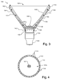
- Fig. 3 illustrates a cross-sectional view of the LED lamp 100 and Fig. 4 is a plan view of the top of the LED lamp 100.
- LED lamp 100 includes a parabolic optical reflector 110 or other optical element, such as total internal reflector (TIR), to control the direction of the emitted light.
- TIR total internal reflector
- the term optical reflector 110 will be used herein. However, it should be understood that use of the term optical reflector 110 refers to any element that controls the direction of the emitted light, including a parabolic reflector and a TIR. If desired, optical reflector 110 may extend beyond the opening 102a of the shell 102. As illustrated in Figs. 3 and 4, a space is defined between the shell 102 and the optical reflector 110. The space between the shell 102 and optical reflector 110 serves as an air channel 111 as will be discussed in more detail below.
- the optical reflector 110 is coupled to the shell 102 at the opening 102a of the shell 102 by a plurality of support fins 112.
- the optical reflector 110 may be attached to the shell 102 with glue, clips or spring tabs, by welding or by any other appropriate attachment means.
- the shell 102, the optical reflector 110 and the support fins 112 define a plurality of apertures 114, which serve as air exhaust or intake ports. It should be understood, that if desired, support fins 112 may be located elsewhere, e.g., within channel 111, so that only a single aperture 114 is formed, as defined by the shell 102 and the optical reflector 110.
- the LED lamp 100 includes an AC/DC converter 116 that converts the AC power from the screw base 104 to DC power.
- AC/DC converters are well known.
- the AC/DC converter 116 may be any conventional converter that is small enough to fit in the LED lamp 100 near the screw base 104.
- An LED 120 is located at the base of the optical reflector 110 such that the optical reflector 110 can control the direction of the light emitted from the light emitting diode.
- the LED 120 is electrically coupled to the AC/DC converter 116.
- the LED 120 is, by way of example, a Luxeon 500lm LED, which can be purchased from Lumileds Lighting U.S., LLC, located in San Jose, California. It should be understood that any desired LED may be used with the present invention.
- Fig. 3 illustrates a single LED 120 in the LED lamp 100, it should be understood that if desired, a plurality of LEDs may be used to generate the desired luminosity or the desired color of light.
- the LED 120 is mounted to a heat sink 130 by bolts, rivets, solder or any other appropriate mounting method.
- the heat sink 130 is, e.g., manufactured from aluminum, aluminum alloy, brass, steel, stainless steel, or any other thermally conductive materials, compounds, or composites.
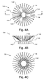
- Heat sink 130 is shown in more detail in Figs. 4A, 4B, and 4C, which show a top plan view, cross-sectional view (along line AA in Fig. 4A), and bottom plan view of heat sink 130 respectively.
- heat sink 130 includes a base 132 and a plurality of fins 136 extending from the base. If desired, heat pipes may be used in place of fins 136, or a combination of fins and heat pipes may be used.
- the base 132 of the heat sink 130 includes a plurality of apertures 134, which are used to mount the LED 120 to the top surface of the base 132 of the heat sink 130, e.g., by bolts or rivets.
- thermally conductive mounting means may be used, such as solder or epoxy.
- the configuration of the heat sink may differ, for example, in a differently shaped LED lamp.
- the Fig. 3 illustrates the fins of heat sink 130 extending partially into the channel 111, it should be understood that, if desired, the fins may extend entirely through the channel 111.
- the need for support fins 112 for the optical reflector 110 may be obviated.
- the heat sink 130 may be held in position by press fitting between the exterior shell 102 and the optical reflector 110.
- the heat sink 130 may be coupled to one or both of the shell 102 and optical reflector 110, e.g., using glue, bolts, rivets or any other appropriate connection means.
- the fins 136 also include apertures 138.
- the apertures 138 are used to mount a motor 140 to the bottom side of the base 132 of the heat sink 130, e.g., using bolts or rivets.
- the motor 140 is use to drive a fan 142.
- the motor and fan are illustrated in Figs. 4A and 4B.
- the motor 130 may be, by way of example, a brushless DC 12V motor and receives power from the AC/DC converter 125.
- the type and size of the motor and fan will depend on the size of the LED lamp 100 and the type of LED and how much heat is produced by the LED.
- an adequate motor 130 and fan 132 may be purchased from Millennium Electronics Inc. located in San Jose, California, as Part No. 1035-C2, which has dimensions of 68x60x10mm and produces 3.7 CFM.
- Millennium Electronics Inc. located in San Jose, California, as Part No. 1035-C2
- other types of motors, fans, and dimensions may be used if desired. www.Mei-thermal.com
- the fan 142 draws air through air inlet apertures 106 and moves the air over the heat sink 130 and through the channel 111 between the shell 102 and the optical reflector 110 and out through the exhaust apertures 114 defined by the shell 102, optical reflector 110 and fins 112.
- the flow of air is illustrated in Fig. 3 by broken arrows 144.
- the flow of air through channel 111, over the heat sink 130, and out exhaust apertures 114 effectively dissipates heat from the heat sink 130, and thus, the LED 120.
- an air flow channel 111 that is in the general direction of the optical reflector 110 and exhaust apertures 114 that direct the flow of air out of the LED lamp 100 in the same general direction as the light produced by the LED lamp 100 is particularly advantageous where the LED lamp 100 is placed in a recessed area with limited space, such as that illustrated in Fig. 1.
- the form factor the LED lamp 100 can advantageously remain as small as a conventional light bulb while heat produced by the LED is effectively dissipated.
- motor 140 and fan 142 may be located in locations other than that shown in Fig. 3.
- a motor and fan may be located near the opening 102a of the LED lamp 100 or within the channel 111.
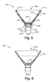
- Fig. 5 illustrates a cross sectional view of a LED lamp 200, which is similar to LED lamp 100, like designated elements being the same.
- LED lamp 200 has the motor 240 and fan 242 reversed, with respect to the embodiment illustrated in Fig. 3.
- the motor 240 is mounted to a plate 203 near the base 104 of the shell 102.
- air is drawn through apertures 114, which thus serve as air inlet ports.
- the air is pulled through channel 111 and over the heat sink 130 and out apertures 106, which thus serve as exhaust ports.
- the air is illustrated in Fig. 5 as arrows 244.
- Fig. 6 illustrates a cross-sectional view of an LED lamp 300 in accordance with another embodiment of the present invention.
- LED lamp 300 is similar to LED lamp 100, like designated elements being the same.
- LED lamp 300 also includes another set of apertures 314 that are approximately equally spaced around the perimeter of the shell 102 at approximately half the distance between the opening 102a and the LED 120.
- Apertures 314 are illustrated with broken lines in Fig. 6. The precise location of the apertures 314 may vary, but apertures 314 should be located to permit an adequate air flow over the heat sink 130 to produce the desired dissipation of heat.
- apertures 106 it should be understood that if desired, a single, relatively large aperture may be used in place of apertures 314.
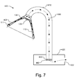
- Fig. 7 illustrates a cross-sectional view of an LED lamp 400 in accordance with another embodiment of the present invention, in which the fan and motor are not necessarily adjacent to the heat sink 130 or channel 111, but are in flow communication with channel 111, i.e., capable of moving air through the channel 111.
- LED lamp 400 is similar to LED lamp 200, like designated elements being the same.
- LED lamp 400 includes a hollow neck 410 that is coupled to and supports the shell 402 (along with the other components, such as the optical reflector 110, LED 120, etc.) and a base 420.
- the neck 410 may be rigid or flexible.
- the LED lamp 400 includes a motor 440 and fan 442 that are located within the base 420.
- the fan 442 draws air through channel 111, over the heat sink 130 and through the neck 410 to the base 420, where the air is expelled through exhaust port 422.
- the air is illustrated in Fig. 5 as arrows 444.
- the flow of air may be in the reverse direction, e.g., by reversing the orientation of the motor 440 and fan 442.
- the motor and fan may still be located adjacent to the heat sink 130, while causing the air to flow through the neck 410 and out the exhaust port 422 in the base.
- the fan and/or the intake or exhaust apertures may be in locations that are not adjacent to the heat sink 130 or channel 111.
- Fig. 8 illustrates a cross-sectional view of another embodiment of an LED lamp 500.
- LED lamp 500 is similar to LED lamp 100, like designated elements being the same.
- an additional shell 502 is provide around shell 102.
- an AC/DC converter circuit 504 is provided within the shell 502.
- Apertures 506 within the shell 502 allow air to enter and flow over the AC/DC converter circuit 504 prior to being drawn into apertures 106, as indicated by arrows 508.
- the AC/DC converter circuit 504 advantageously is cooled.
- the air flow may be reversed so that the air exits through apertures 506.
Landscapes
- Engineering & Computer Science (AREA)
- General Engineering & Computer Science (AREA)
- Physics & Mathematics (AREA)
- Microelectronics & Electronic Packaging (AREA)
- Optics & Photonics (AREA)
- Geometry (AREA)
- Arrangement Of Elements, Cooling, Sealing, Or The Like Of Lighting Devices (AREA)
- Non-Portable Lighting Devices Or Systems Thereof (AREA)
Abstract
Description
Claims (22)
- An apparatus comprising:a shell;an optical reflector disposed at least partially within the shell, wherein a space is formed between the optical reflector and the shell;at least one light emitting diode disposed within the optical reflector;a heat sink disposed at least partially within the shell, the light emitting diode being mounted to the heat sink; anda motor and a fan in flow communication with the space, the fan being configured to move air over the heat sink and through the space.
- The apparatus of Claim 1, wherein the fan is configured to move air over the heat sink before moving air through the space.
- The apparatus of Claim 1, wherein the shell has at least one air inlet aperture, the fan drawing air through the air inlet aperture.
- The apparatus of Claim 3, wherein the shell and optical reflector define at least one air exhaust aperture, wherein air is expelled through the at least one air exhaust aperture after moving over the heat sink.
- The apparatus of Claim 3, wherein the shell further has at least one air exhaust aperture, wherein air is expelled through the at least one air exhaust aperture after moving over the heat sink.
- The apparatus of Claim 1, wherein the shell and optical reflector define at least one air inlet aperture and the shell further has at least one air exhaust aperture, wherein the fan draws air through the air inlet aperture and moves air through the space, over the heat sink and through the air exhaust aperture.
- The apparatus of Claim 3, wherein the apparatus further comprises a base coupled to the shell, wherein the shell has a plurality of air inlet apertures located near the base.
- The apparatus of Claim 1, wherein the heat sink includes at least one of a plurality of fins and a plurality of heat pipes that extend into the space.
- The apparatus of Claim 1, wherein the motor and fan are within the shell.
- The apparatus of Claim 1, further comprising a hollow neck coupled to the shell and a base coupled to the hollow neck, wherein the motor and fan are within the base.
- A method of cooling a light emitting diode in a lamp, the lamp including an optical reflector that directs the light emitted from the light emitting diode, the method comprising:drawing air through at least one air inlet aperture;moving the air over a heat sink that is coupled to the light emitting diode;moving the air along at least a portion of the optical reflector; andexpelling the air through at least one air exhaust aperture.
- The method of Claim 11, wherein the air is moved along at least a portion of the optical reflector before the air is moved over the heat sink.
- The method of Claim 11, wherein moving the air along at least a portion of the optical reflector comprises moving the air through a space defined by the optical reflector and an external shell that surrounds at least a portion of the optical reflector.
- The method of Claim 11, wherein drawing air, moving the air over a heat sink, moving the air along at least a portion of the optical reflector, and expelling the air is performed by a fan.
- The method of Claim 11, wherein air is expelled through at least one air exhaust aperture defined by the optical reflector and an external shell that surrounds at least a portion of the optical reflector.
- The method of Claim 11, further comprising moving the air through a hollow element that supports the optical reflector and a base that is coupled to the hollow element.
- An apparatus comprising:a light emitting diode;an optical reflector that controls the direction of light emitted from the light emitting diode;a heat sink, the light emitting diode being mounted on the heat sink;a fan for moving air over the heat sink; andan air flow channel through which the fan moves air, the air flow channel follows the general outline of the optical reflector.
- The apparatus of Claim 17, wherein the air flow channel is at least partially defined by the optical reflector.
- The apparatus of Claim 18, further comprising an exterior shell in which the optical reflector is at least partially disposed, wherein the air flow channel is further defined by the exterior shell.
- The apparatus of Claim 19, wherein the exterior shell has a plurality of apertures through which air is drawn prior to being moved over the heat sink.
- The apparatus of Claim 17, wherein the heat sink comprises at least one of a plurality of fins and a plurality of heat pipes that extend in the general direction of the optical reflector.
- The apparatus of Claim 17, further comprising a hollow support element that is coupled to the optical reflector and heat sink, wherein the hollow support element defines a portion of the air flow channel.
Applications Claiming Priority (2)
| Application Number | Priority Date | Filing Date | Title |
|---|---|---|---|
| US723711 | 2003-11-26 | ||
| US10/723,711 US7144135B2 (en) | 2003-11-26 | 2003-11-26 | LED lamp heat sink |
Publications (3)
| Publication Number | Publication Date |
|---|---|
| EP1561993A2 true EP1561993A2 (en) | 2005-08-10 |
| EP1561993A3 EP1561993A3 (en) | 2006-12-13 |
| EP1561993B1 EP1561993B1 (en) | 2016-10-26 |
Family
ID=34592348
Family Applications (1)
| Application Number | Title | Priority Date | Filing Date |
|---|---|---|---|
| EP04105649.0A Expired - Lifetime EP1561993B1 (en) | 2003-11-26 | 2004-11-10 | LED lamps and method of cooling their LED |
Country Status (4)
| Country | Link |
|---|---|
| US (1) | US7144135B2 (en) |
| EP (1) | EP1561993B1 (en) |
| JP (1) | JP4757480B2 (en) |
| TW (1) | TWI368008B (en) |
Cited By (3)
| Publication number | Priority date | Publication date | Assignee | Title |
|---|---|---|---|---|
| DE102010013310A1 (en) | 2010-03-29 | 2011-09-29 | Panasonic Electric Works Vossloh-Schwabe Gmbh | Operating circuit for operating a fan for a light module |
| EP2525137A1 (en) | 2011-05-20 | 2012-11-21 | Ansorg GmbH | Lighting device with an LED module as illuminant and a fan for cooling |
| RU2468289C2 (en) * | 2006-07-28 | 2012-11-27 | Конинклейке Филипс Электроникс Н.В. | Lighting module with similar directions of heat and light propagation |
Families Citing this family (410)
| Publication number | Priority date | Publication date | Assignee | Title |
|---|---|---|---|---|
| US20070267976A1 (en) * | 2003-05-05 | 2007-11-22 | Bohler Christopher L | Led-Based Light Bulb |
| KR200350484Y1 (en) * | 2004-02-06 | 2004-05-13 | 주식회사 대진디엠피 | Corn Type LED Light |
| US10575376B2 (en) | 2004-02-25 | 2020-02-25 | Lynk Labs, Inc. | AC light emitting diode and AC LED drive methods and apparatus |
| WO2011143510A1 (en) | 2010-05-12 | 2011-11-17 | Lynk Labs, Inc. | Led lighting system |
| US10499465B2 (en) | 2004-02-25 | 2019-12-03 | Lynk Labs, Inc. | High frequency multi-voltage and multi-brightness LED lighting devices and systems and methods of using same |
| TWI263008B (en) * | 2004-06-30 | 2006-10-01 | Ind Tech Res Inst | LED lamp |
| DE102004042186B4 (en) * | 2004-08-31 | 2010-07-01 | Osram Opto Semiconductors Gmbh | Optoelectronic component |
| DE202004013773U1 (en) * | 2004-09-04 | 2004-11-11 | Zweibrüder Optoelectronics GmbH | lamp |
| US7758223B2 (en) * | 2005-04-08 | 2010-07-20 | Toshiba Lighting & Technology Corporation | Lamp having outer shell to radiate heat of light source |
| US7633177B2 (en) * | 2005-04-14 | 2009-12-15 | Natural Forces, Llc | Reduced friction wind turbine apparatus and method |
| WO2006119582A1 (en) * | 2005-05-13 | 2006-11-16 | Tama Berkeljon | Lighting apparatus |
| US9412926B2 (en) | 2005-06-10 | 2016-08-09 | Cree, Inc. | High power solid-state lamp |
| NL1029231C2 (en) * | 2005-06-10 | 2007-01-12 | Lemnis Lighting Ip Gmbh | Lighting device and solid-state light source. |
| KR20080017023A (en) * | 2005-06-10 | 2008-02-25 | 렘니스 라이팅 아이피 게엠베하 | Illumination device and solid state light source |
| US7527396B2 (en) * | 2005-06-21 | 2009-05-05 | Osram Sylvania Inc. | Illumination device with thermally isolated integral power supply |
| DE102005038186B4 (en) * | 2005-08-12 | 2007-08-30 | Daimlerchrysler Ag | Headlight module for motor vehicles |
| US7922361B2 (en) * | 2005-08-19 | 2011-04-12 | Neobulb Technologies, Inc. | Light-emitting diode illuminating equipment with high power and high heat dissipation efficiency |
| TWM286407U (en) * | 2005-10-11 | 2006-01-21 | Augux Co Ltd | Heat dissipation module |
| US7771095B2 (en) * | 2005-10-26 | 2010-08-10 | Abl Ip Holding, Llc | Lamp thermal management system |
| DE102006003057A1 (en) * | 2006-01-20 | 2007-07-26 | Phoenix Contact Gmbh & Co. Kg | Ink drying lamp especially for serial printer has an improved reflector with elliptical and plane surfaces to focus onto the printed area |
| US20100177519A1 (en) * | 2006-01-23 | 2010-07-15 | Schlitz Daniel J | Electro-hydrodynamic gas flow led cooling system |
| WO2007087327A2 (en) * | 2006-01-25 | 2007-08-02 | Cree Led Lighting Solutions, Inc. | Circuit for lighting device, and method of lighting |
| US20080000467A1 (en) * | 2006-02-16 | 2008-01-03 | Design Annex | Disposable charcoal lighting apparatus |
| US7488097B2 (en) * | 2006-02-21 | 2009-02-10 | Cml Innovative Technologies, Inc. | LED lamp module |
| TWM297441U (en) * | 2006-03-30 | 2006-09-11 | Cheng-Jiun Jian | LED projection light source module |
| US20070230185A1 (en) * | 2006-03-31 | 2007-10-04 | Shuy Geoffrey W | Heat exchange enhancement |
| US7593229B2 (en) * | 2006-03-31 | 2009-09-22 | Hong Kong Applied Science & Technology Research Institute Co. Ltd | Heat exchange enhancement |
| US7440280B2 (en) * | 2006-03-31 | 2008-10-21 | Hong Kong Applied Science & Technology Research Institute Co., Ltd | Heat exchange enhancement |
| US7784969B2 (en) * | 2006-04-12 | 2010-08-31 | Bhc Interim Funding Iii, L.P. | LED based light engine |
| US7648257B2 (en) | 2006-04-21 | 2010-01-19 | Cree, Inc. | Light emitting diode packages |
| US7625103B2 (en) * | 2006-04-21 | 2009-12-01 | Cree, Inc. | Multiple thermal path packaging for solid state light emitting apparatus and associated assembling methods |
| EP2013919A2 (en) | 2006-05-02 | 2009-01-14 | Superbulbs, Inc. | Method of light dispersion and preferential scattering of certain wavelengths of light for light-emitting diodes and bulbs constructed therefrom |
| US8702257B2 (en) | 2006-05-02 | 2014-04-22 | Switch Bulb Company, Inc. | Plastic LED bulb |
| US8547002B2 (en) | 2006-05-02 | 2013-10-01 | Switch Bulb Company, Inc. | Heat removal design for LED bulbs |
| US8596819B2 (en) | 2006-05-31 | 2013-12-03 | Cree, Inc. | Lighting device and method of lighting |
| US7824075B2 (en) * | 2006-06-08 | 2010-11-02 | Lighting Science Group Corporation | Method and apparatus for cooling a lightbulb |
| JP3965419B1 (en) * | 2006-08-23 | 2007-08-29 | 株式会社モモ・アライアンス | Lighting device |
| WO2008036873A2 (en) * | 2006-09-21 | 2008-03-27 | Cree Led Lighting Solutions, Inc. | Lighting assemblies, methods of installing same, and methods of replacing lights |
| CN101310567A (en) * | 2006-10-24 | 2008-11-19 | 照宏光电科技股份有限公司 | lighting device |
| EP2095014B1 (en) * | 2006-11-14 | 2017-05-10 | Cree, Inc. | Light engine assemblies |
| JP5324458B2 (en) * | 2006-11-14 | 2013-10-23 | クリー インコーポレイテッド | Lighting assembly and components for the lighting assembly |
| KR200447577Y1 (en) | 2006-11-24 | 2010-02-19 | 라이트하우스 테크놀로지 씨오., 엘티디. | Light emitting device of light emitting diode module |
| TWM310984U (en) * | 2006-11-28 | 2007-05-01 | Primo Lite Co Ltd | Lamp structure of light emitting diode |
| KR101408613B1 (en) * | 2006-11-30 | 2014-06-20 | 크리, 인코포레이티드 | Self-ballasted solid state lighting devices |
| US7549786B2 (en) * | 2006-12-01 | 2009-06-23 | Cree, Inc. | LED socket and replaceable LED assemblies |
| US20080149305A1 (en) * | 2006-12-20 | 2008-06-26 | Te-Chung Chen | Heat Sink Structure for High Power LED Lamp |
| CN101000131A (en) * | 2007-01-06 | 2007-07-18 | 宁波艾里根斯电器有限公司 | LED lamp |
| US20110128742A9 (en) * | 2007-01-07 | 2011-06-02 | Pui Hang Yuen | High efficiency low cost safety light emitting diode illumination device |
| US7677770B2 (en) * | 2007-01-09 | 2010-03-16 | Lighting Science Group Corporation | Thermally-managed LED-based recessed down lights |
| ITMI20070120A1 (en) | 2007-01-26 | 2008-07-27 | Piper Lux S R L | LED SPOTLIGHT |
| JP2008186694A (en) * | 2007-01-30 | 2008-08-14 | Hayashi Watch-Works Co Ltd | Lighting device |
| US8258682B2 (en) | 2007-02-12 | 2012-09-04 | Cree, Inc. | High thermal conductivity packaging for solid state light emitting apparatus and associated assembling methods |
| EP1975505A1 (en) * | 2007-03-26 | 2008-10-01 | Koninklijke Philips Electronics N.V. | Lighting device |
| US7549774B2 (en) * | 2007-04-24 | 2009-06-23 | Hong Kuan Technology Co., Ltd. | LED lamp with plural radially arranged heat sinks |
| KR101555894B1 (en) * | 2007-05-04 | 2015-09-30 | 코닌클리케 필립스 엔.브이. | Led-based fixtures and related methods for thermal management |
| US7992294B2 (en) * | 2007-05-25 | 2011-08-09 | Molex Incorporated | Method of manufacturing an interconnect device which forms a heat sink and electrical connections between a heat generating device and a power source |
| CN101368719B (en) * | 2007-08-13 | 2011-07-06 | 太一节能系统股份有限公司 | LED lamps |
| DE102007040444B8 (en) * | 2007-08-28 | 2013-10-17 | Osram Gmbh | Led lamp |
| JP4670850B2 (en) * | 2007-08-31 | 2011-04-13 | 市光工業株式会社 | Vehicle lighting |
| US8123381B1 (en) * | 2007-09-07 | 2012-02-28 | J&J Electronics, Inc. | LED lighting systems and methods useable for replacement of underwater niche lights and other applications |
| CN101387388B (en) * | 2007-09-11 | 2011-11-30 | 富士迈半导体精密工业(上海)有限公司 | Luminous diode lighting device |
| US8100556B2 (en) | 2007-09-19 | 2012-01-24 | Cooper Technologies, Inc. | Light fixture with an adjustable optical distribution |
| US8206009B2 (en) | 2007-09-19 | 2012-06-26 | Cooper Technologies Company | Light emitting diode lamp source |
| US20090080189A1 (en) | 2007-09-21 | 2009-03-26 | Cooper Technologies Company | Optic Coupler for Light Emitting Diode Fixture |
| CN101809366B (en) * | 2007-09-27 | 2013-01-02 | 皇家飞利浦电子股份有限公司 | Lighting device and method of cooling a lighting device |
| US8186855B2 (en) * | 2007-10-01 | 2012-05-29 | Wassel James J | LED lamp apparatus and method of making an LED lamp apparatus |
| RU2349988C1 (en) * | 2007-10-02 | 2009-03-20 | Открытое акционерное общество "Научно-исследовательский институт полупроводниковых приборов" (ОАО "НИИПП") | Semiconductor light source |
| US8439528B2 (en) | 2007-10-03 | 2013-05-14 | Switch Bulb Company, Inc. | Glass LED light bulbs |
| US11317495B2 (en) | 2007-10-06 | 2022-04-26 | Lynk Labs, Inc. | LED circuits and assemblies |
| US11297705B2 (en) | 2007-10-06 | 2022-04-05 | Lynk Labs, Inc. | Multi-voltage and multi-brightness LED lighting devices and methods of using same |
| PL3051586T3 (en) * | 2007-10-09 | 2018-08-31 | Philips Lighting North America Corporation | Integrated led-based luminaire for general lighting |
| JP4569683B2 (en) * | 2007-10-16 | 2010-10-27 | 東芝ライテック株式会社 | Light emitting element lamp and lighting apparatus |
| US8415695B2 (en) | 2007-10-24 | 2013-04-09 | Switch Bulb Company, Inc. | Diffuser for LED light sources |
| US20090122552A1 (en) * | 2007-11-09 | 2009-05-14 | Chuntlon Enterprise Co., Ltd. | Low power consumption high illumination LED lamp |
| EP2232134A4 (en) * | 2007-11-19 | 2013-04-17 | Nexxus Lighting Inc | APPARATUS FOR SERVING HOUSING IN A LIGHTING ASSEMBLY |
| US7974099B2 (en) * | 2007-11-19 | 2011-07-05 | Nexxus Lighting, Inc. | Apparatus and methods for thermal management of light emitting diodes |
| KR200440554Y1 (en) * | 2007-11-27 | 2008-06-17 | 광성전기산업(주) | LED lamp for bulb type AC power |
| TWM332793U (en) * | 2007-11-28 | 2008-05-21 | Cooler Master Co Ltd | Heat radiating structure and the lighting apparatus |
| KR101253821B1 (en) * | 2007-12-07 | 2013-04-12 | 오스람 게엠베하 | Lighting device including heat sink and heat sink |
| JP2011505702A (en) * | 2007-12-07 | 2011-02-24 | オスラム ゲゼルシャフト ミット ベシュレンクテル ハフツング | Heat sink and lighting device including heat sink |
| US8118447B2 (en) | 2007-12-20 | 2012-02-21 | Altair Engineering, Inc. | LED lighting apparatus with swivel connection |
| US8322881B1 (en) | 2007-12-21 | 2012-12-04 | Appalachian Lighting Systems, Inc. | Lighting fixture |
| US7712918B2 (en) | 2007-12-21 | 2010-05-11 | Altair Engineering , Inc. | Light distribution using a light emitting diode assembly |
| JP5353216B2 (en) * | 2008-01-07 | 2013-11-27 | 東芝ライテック株式会社 | LED bulb and lighting fixture |
| US7841756B2 (en) * | 2008-01-31 | 2010-11-30 | Honda Motor Co., Ltd. | Vehicle lamp assembly |
| US8246202B2 (en) * | 2008-02-13 | 2012-08-21 | Mart Gary K | Light emitting diode bulb |
| US7771089B2 (en) * | 2008-02-14 | 2010-08-10 | Gm Global Technology Operations, Inc. | High intensity and low power signaling device with heat dissipation system |
| JP5019264B2 (en) * | 2008-02-29 | 2012-09-05 | 東芝ライテック株式会社 | Light emitting element lamp and lighting apparatus |
| US7887216B2 (en) | 2008-03-10 | 2011-02-15 | Cooper Technologies Company | LED-based lighting system and method |
| WO2009115063A1 (en) * | 2008-03-17 | 2009-09-24 | Osram Gesellschaft mit beschränkter Haftung | Arrangement, lamp arrangement and method for emitting light |
| TW200940881A (en) * | 2008-03-18 | 2009-10-01 | Pan Jit Internat Inc | LED lamp with thermal convection and thermal conduction heat dissipating effect, and heat dissipation module thereof |
| USD633649S1 (en) | 2008-03-31 | 2011-03-01 | Cooper Technologies Company | LED light fixture |
| US8360599B2 (en) | 2008-05-23 | 2013-01-29 | Ilumisys, Inc. | Electric shock resistant L.E.D. based light |
| DK2276973T3 (en) * | 2008-05-23 | 2013-01-14 | Huizhou Light Engine Ltd | NON-DOUBLE REFLECTIVE LED LIGHTING WITH HEAT RECOVERY |
| US20090296387A1 (en) * | 2008-05-27 | 2009-12-03 | Sea Gull Lighting Products, Llc | Led retrofit light engine |
| US8304970B2 (en) * | 2008-06-02 | 2012-11-06 | Sunovia Energy Technologies, Inc. | Light unit with induced convection heat sink |
| US8167459B2 (en) * | 2008-06-25 | 2012-05-01 | Bwt Property, Inc. | LED lighting fixture |
| CN101978209A (en) * | 2008-06-27 | 2011-02-16 | 东芝照明技术株式会社 | Light-emitting element lamps and lighting equipment |
| CN101619822B (en) * | 2008-06-30 | 2012-12-19 | 鸿富锦精密工业(深圳)有限公司 | Lighting device |
| US7976196B2 (en) | 2008-07-09 | 2011-07-12 | Altair Engineering, Inc. | Method of forming LED-based light and resulting LED-based light |
| TWI409408B (en) * | 2008-07-18 | 2013-09-21 | Hon Hai Prec Ind Co Ltd | Illuminating apparatus |
| US9062871B2 (en) * | 2008-07-21 | 2015-06-23 | David M. Medinis | LED lamp with air-cooled heat sink |
| US7575346B1 (en) | 2008-07-22 | 2009-08-18 | Sunonwealth Electric Machine Industry Co., Ltd. | Lamp |
| CN101639163B (en) * | 2008-07-30 | 2012-02-15 | 建准电机工业股份有限公司 | lamps |
| EP2154419B1 (en) * | 2008-07-31 | 2016-07-06 | Toshiba Lighting & Technology Corporation | Self-ballasted lamp |
| JP2010040222A (en) * | 2008-07-31 | 2010-02-18 | Toshiba Lighting & Technology Corp | Lighting system |
| US7946729B2 (en) | 2008-07-31 | 2011-05-24 | Altair Engineering, Inc. | Fluorescent tube replacement having longitudinally oriented LEDs |
| US8674626B2 (en) | 2008-09-02 | 2014-03-18 | Ilumisys, Inc. | LED lamp failure alerting system |
| CN101373063A (en) * | 2008-09-05 | 2009-02-25 | 汕尾市大利荣耀灯饰工业有限公司 | Heat radiating device of long service life and energy-saving LED sending light |
| US8143769B2 (en) * | 2008-09-08 | 2012-03-27 | Intematix Corporation | Light emitting diode (LED) lighting device |
| TWI349085B (en) * | 2008-09-09 | 2011-09-21 | Sunonwealth Electr Mach Ind Co | Lamp |
| AU2009291720A1 (en) * | 2008-09-11 | 2010-03-18 | Revolution Lighting Technologies, Inc. | Light and process of manufacturing a light |
| US8256924B2 (en) | 2008-09-15 | 2012-09-04 | Ilumisys, Inc. | LED-based light having rapidly oscillating LEDs |
| US20100073956A1 (en) * | 2008-09-23 | 2010-03-25 | Edison Opto Corporation | Heat dissipation module with light guiding fins |
| US7914182B2 (en) * | 2008-09-30 | 2011-03-29 | GE Lighting Soutions, LLC | Decorative light fixture including cooling system |
| US7902761B2 (en) * | 2008-10-03 | 2011-03-08 | Next Gen Illumination, Inc | Dimmable LED lamp |
| US8500305B2 (en) * | 2008-10-03 | 2013-08-06 | Cree, Inc. | Active thermal management systems for enclosed lighting and modular lighting systems incorporating the same |
| FR2936858A1 (en) * | 2008-10-07 | 2010-04-09 | Luc Philippe Lucien Robichon | AERATION DEVICE FOR LIGHTING SYSTEMS IN A CEILING OR A FALSE CEILING. |
| US8123382B2 (en) * | 2008-10-10 | 2012-02-28 | Cooper Technologies Company | Modular extruded heat sink |
| KR100901180B1 (en) * | 2008-10-13 | 2009-06-04 | 현대통신 주식회사 | Heat dissipation member with variable heat dissipation path and LED emitting lamp |
| KR100903192B1 (en) * | 2008-10-17 | 2009-06-17 | 현대통신 주식회사 | LED light emitting lamp with double heat sink structure using nano spreader |
| US8324817B2 (en) | 2008-10-24 | 2012-12-04 | Ilumisys, Inc. | Light and light sensor |
| US8444292B2 (en) | 2008-10-24 | 2013-05-21 | Ilumisys, Inc. | End cap substitute for LED-based tube replacement light |
| US7938562B2 (en) | 2008-10-24 | 2011-05-10 | Altair Engineering, Inc. | Lighting including integral communication apparatus |
| US8901823B2 (en) | 2008-10-24 | 2014-12-02 | Ilumisys, Inc. | Light and light sensor |
| US8214084B2 (en) | 2008-10-24 | 2012-07-03 | Ilumisys, Inc. | Integration of LED lighting with building controls |
| US8653984B2 (en) | 2008-10-24 | 2014-02-18 | Ilumisys, Inc. | Integration of LED lighting control with emergency notification systems |
| KR100902631B1 (en) * | 2008-10-24 | 2009-06-12 | 현대통신 주식회사 | LED light emitting lamp of circular structure using nanospreader |
| US20100148652A1 (en) * | 2008-10-28 | 2010-06-17 | Jan Vetrovec | Solid state lighting |
| US20100109499A1 (en) * | 2008-11-03 | 2010-05-06 | Vilgiate Anthony W | Par style lamp having solid state light source |
| US20100118536A1 (en) * | 2008-11-10 | 2010-05-13 | Bliss Holdings, Llc | Lighting device for accent lighting & methods of use thereof |
| KR100905502B1 (en) * | 2008-11-10 | 2009-07-01 | 현대통신 주식회사 | Led lighting device |
| TWI394918B (en) * | 2008-11-28 | 2013-05-01 | Young Green Energy Co | Lighting module and lighting system |
| AU2009202051C1 (en) * | 2008-12-09 | 2010-09-23 | Manfred Oechsle | PAR38-Compatible spot/flood light "enviropar-l" with LEDs |
| US8237377B2 (en) * | 2008-12-11 | 2012-08-07 | Michael Blair Hopper | Energy efficient lighting system and method |
| CN102292594A (en) | 2008-12-11 | 2011-12-21 | 莱德尼德控股股份有限公司 | Led lamp system |
| US8256934B2 (en) * | 2009-01-07 | 2012-09-04 | Troy-Csl Lighting, Inc. | Puck type light fixture |
| US20100177521A1 (en) * | 2009-01-14 | 2010-07-15 | Yeh-Chiang Technology Corp. | Led lamp |
| US8491162B2 (en) * | 2009-01-14 | 2013-07-23 | Zhongshan Weiqiang Technology Co., Ltd. | LED lamp |
| US8556452B2 (en) | 2009-01-15 | 2013-10-15 | Ilumisys, Inc. | LED lens |
| DE202009000699U1 (en) * | 2009-01-16 | 2009-03-26 | Rd System-Leuchten Ag | Bulb module with an LED assembly |
| US8362710B2 (en) | 2009-01-21 | 2013-01-29 | Ilumisys, Inc. | Direct AC-to-DC converter for passive component minimization and universal operation of LED arrays |
| JP5379166B2 (en) | 2009-01-20 | 2013-12-25 | パナソニック株式会社 | Lighting device |
| US8664880B2 (en) | 2009-01-21 | 2014-03-04 | Ilumisys, Inc. | Ballast/line detection circuit for fluorescent replacement lamps |
| US20100187963A1 (en) * | 2009-01-28 | 2010-07-29 | Guy Vaccaro | Heat Sink for Passive Cooling of a Lamp |
| US20100208460A1 (en) * | 2009-02-19 | 2010-08-19 | Cooper Technologies Company | Luminaire with led illumination core |
| JP5333758B2 (en) * | 2009-02-27 | 2013-11-06 | 東芝ライテック株式会社 | Lighting device and lighting fixture |
| US8057075B2 (en) * | 2009-03-13 | 2011-11-15 | Sunonwealth Electric Machine Industry Co., Ltd. | Lamp device |
| DE202009004252U1 (en) * | 2009-03-31 | 2010-05-27 | BÄRO GmbH & Co. KG | lamp |
| KR100961840B1 (en) * | 2009-10-30 | 2010-06-08 | 화우테크놀러지 주식회사 | Led lamp |
| KR100914833B1 (en) * | 2009-04-16 | 2009-09-02 | 방원식 | Light for bicycle |
| JP2010251248A (en) * | 2009-04-20 | 2010-11-04 | Ryosan Co Ltd | Heat sink for LED lighting and manufacturing method thereof |
| TWM364281U (en) * | 2009-04-28 | 2009-09-01 | Kwo Ger Metal Technology Inc | LED light-emitting module |
| US8952613B2 (en) * | 2009-05-12 | 2015-02-10 | Leroy E. Anderson | LED room light |
| US8330381B2 (en) | 2009-05-14 | 2012-12-11 | Ilumisys, Inc. | Electronic circuit for DC conversion of fluorescent lighting ballast |
| US8142057B2 (en) * | 2009-05-19 | 2012-03-27 | Schneider Electric USA, Inc. | Recessed LED downlight |
| US20100295436A1 (en) | 2009-05-19 | 2010-11-25 | Alex Horng | Lamp |
| US8299695B2 (en) | 2009-06-02 | 2012-10-30 | Ilumisys, Inc. | Screw-in LED bulb comprising a base having outwardly projecting nodes |
| CA2765200A1 (en) | 2009-06-23 | 2011-01-13 | Altair Engineering, Inc. | Illumination device including leds and a switching power control system |
| RU2573424C2 (en) | 2009-06-25 | 2016-01-20 | Конинклейке Филипс Электроникс Н.В. | Heat-regulation device |
| JP5348410B2 (en) * | 2009-06-30 | 2013-11-20 | 東芝ライテック株式会社 | Lamp with lamp and lighting equipment |
| JP5354191B2 (en) * | 2009-06-30 | 2013-11-27 | 東芝ライテック株式会社 | Light bulb shaped lamp and lighting equipment |
| WO2011005314A2 (en) * | 2009-07-06 | 2011-01-13 | Rodriquez Edward T | Cooling solid state high-brightness white-light illumination sources |
| CA2768777C (en) | 2009-07-21 | 2017-11-28 | Cooper Technologies Company | Interfacing a light emitting diode (led) module to a heat sink assembly, a light reflector and electrical circuits |
| US8596837B1 (en) | 2009-07-21 | 2013-12-03 | Cooper Technologies Company | Systems, methods, and devices providing a quick-release mechanism for a modular LED light engine |
| JP2011049527A (en) * | 2009-07-29 | 2011-03-10 | Toshiba Lighting & Technology Corp | Led lighting equipment |
| US7932532B2 (en) * | 2009-08-04 | 2011-04-26 | Cree, Inc. | Solid state lighting device with improved heatsink |
| US8596825B2 (en) * | 2009-08-04 | 2013-12-03 | 3M Innovative Properties Company | Solid state light with optical guide and integrated thermal guide |
| US20110037367A1 (en) * | 2009-08-11 | 2011-02-17 | Ventiva, Inc. | Solid-state light bulb having ion wind fan and internal heat sinks |
| JP5601512B2 (en) * | 2009-09-14 | 2014-10-08 | 東芝ライテック株式会社 | Light emitting device and lighting device |
| EP2480829B1 (en) | 2009-09-23 | 2014-04-16 | Koninklijke Philips N.V. | A lighting device |
| JP2011071242A (en) * | 2009-09-24 | 2011-04-07 | Toshiba Lighting & Technology Corp | Light emitting device and illuminating device |
| US8678618B2 (en) | 2009-09-25 | 2014-03-25 | Toshiba Lighting & Technology Corporation | Self-ballasted lamp having a light-transmissive member in contact with light emitting elements and lighting equipment incorporating the same |
| US8324789B2 (en) * | 2009-09-25 | 2012-12-04 | Toshiba Lighting & Technology Corporation | Self-ballasted lamp and lighting equipment |
| JP2011091033A (en) * | 2009-09-25 | 2011-05-06 | Toshiba Lighting & Technology Corp | Light-emitting module, bulb-shaped lamp and lighting equipment |
| CN102032481B (en) * | 2009-09-25 | 2014-01-08 | 东芝照明技术株式会社 | Lamp with base and lighting equipment |
| US8350500B2 (en) | 2009-10-06 | 2013-01-08 | Cree, Inc. | Solid state lighting devices including thermal management and related methods |
| US8264155B2 (en) * | 2009-10-06 | 2012-09-11 | Cree, Inc. | Solid state lighting devices providing visible alert signals in general illumination applications and related methods of operation |
| US20110110095A1 (en) * | 2009-10-09 | 2011-05-12 | Intematix Corporation | Solid-state lamps with passive cooling |
| US9243758B2 (en) * | 2009-10-20 | 2016-01-26 | Cree, Inc. | Compact heat sinks and solid state lamp incorporating same |
| US9217542B2 (en) * | 2009-10-20 | 2015-12-22 | Cree, Inc. | Heat sinks and lamp incorporating same |
| US9030120B2 (en) | 2009-10-20 | 2015-05-12 | Cree, Inc. | Heat sinks and lamp incorporating same |
| CN201526933U (en) * | 2009-10-22 | 2010-07-14 | 沈李豪 | Multilayer heat radiation structure of LED lighting lamp |
| CN102052613B (en) * | 2009-11-04 | 2014-03-26 | 建准电机工业股份有限公司 | lamps |
| WO2011055659A1 (en) | 2009-11-05 | 2011-05-12 | 株式会社エルム | Large led lighting apparatus |
| US20110122630A1 (en) * | 2009-11-26 | 2011-05-26 | Dsem Holdings Sdn. Bhd. | Solid State Lamp Having Vapor Chamber |
| US8525395B2 (en) * | 2010-02-05 | 2013-09-03 | Litetronics International, Inc. | Multi-component LED lamp |
| JP5257622B2 (en) * | 2010-02-26 | 2013-08-07 | 東芝ライテック株式会社 | Light bulb shaped lamp and lighting equipment |
| US10359151B2 (en) | 2010-03-03 | 2019-07-23 | Ideal Industries Lighting Llc | Solid state lamp with thermal spreading elements and light directing optics |
| US9310030B2 (en) | 2010-03-03 | 2016-04-12 | Cree, Inc. | Non-uniform diffuser to scatter light into uniform emission pattern |
| US9057511B2 (en) | 2010-03-03 | 2015-06-16 | Cree, Inc. | High efficiency solid state lamp and bulb |
| US8882284B2 (en) | 2010-03-03 | 2014-11-11 | Cree, Inc. | LED lamp or bulb with remote phosphor and diffuser configuration with enhanced scattering properties |
| US8562161B2 (en) | 2010-03-03 | 2013-10-22 | Cree, Inc. | LED based pedestal-type lighting structure |
| US9024517B2 (en) | 2010-03-03 | 2015-05-05 | Cree, Inc. | LED lamp with remote phosphor and diffuser configuration utilizing red emitters |
| US9052067B2 (en) | 2010-12-22 | 2015-06-09 | Cree, Inc. | LED lamp with high color rendering index |
| US8931933B2 (en) | 2010-03-03 | 2015-01-13 | Cree, Inc. | LED lamp with active cooling element |
| US8632196B2 (en) | 2010-03-03 | 2014-01-21 | Cree, Inc. | LED lamp incorporating remote phosphor and diffuser with heat dissipation features |
| US9625105B2 (en) | 2010-03-03 | 2017-04-18 | Cree, Inc. | LED lamp with active cooling element |
| US9275979B2 (en) | 2010-03-03 | 2016-03-01 | Cree, Inc. | Enhanced color rendering index emitter through phosphor separation |
| US9316361B2 (en) | 2010-03-03 | 2016-04-19 | Cree, Inc. | LED lamp with remote phosphor and diffuser configuration |
| US9062830B2 (en) | 2010-03-03 | 2015-06-23 | Cree, Inc. | High efficiency solid state lamp and bulb |
| US9500325B2 (en) | 2010-03-03 | 2016-11-22 | Cree, Inc. | LED lamp incorporating remote phosphor with heat dissipation features |
| WO2011119958A1 (en) | 2010-03-26 | 2011-09-29 | Altair Engineering, Inc. | Inside-out led bulb |
| CA2794512A1 (en) | 2010-03-26 | 2011-09-29 | Ilumisys, Inc. | Led light tube with dual sided light distribution |
| US8541958B2 (en) | 2010-03-26 | 2013-09-24 | Ilumisys, Inc. | LED light with thermoelectric generator |
| JP2011216437A (en) * | 2010-04-02 | 2011-10-27 | Idemitsu Kosan Co Ltd | Casing for led-lighting system, and the led-lighting system |
| DE102010034996B4 (en) * | 2010-04-07 | 2017-11-02 | Siteco Beleuchtungstechnik Gmbh | luminaire housing |
| KR101163109B1 (en) | 2010-04-15 | 2012-07-09 | 남경훈 | Radiate heat device for lighting equipment |
| US8517574B2 (en) | 2010-04-30 | 2013-08-27 | Sunonwealth Electric Machine Industry Co., Ltd. | Lamp with air channel |
| US8125126B2 (en) * | 2010-05-07 | 2012-02-28 | Industrial Technology Research Institute | Multi-facet light emitting lamp |
| US9157602B2 (en) | 2010-05-10 | 2015-10-13 | Cree, Inc. | Optical element for a light source and lighting system using same |
| US8596821B2 (en) | 2010-06-08 | 2013-12-03 | Cree, Inc. | LED light bulbs |
| US8827504B2 (en) | 2010-06-18 | 2014-09-09 | Rambus Delaware Llc | Light bulb using solid-state light sources |
| US8651708B2 (en) | 2010-06-25 | 2014-02-18 | General Electric Company | Heat transfer system for a light emitting diode (LED) lamp |
| US8454193B2 (en) | 2010-07-08 | 2013-06-04 | Ilumisys, Inc. | Independent modules for LED fluorescent light tube replacement |
| US8596813B2 (en) | 2010-07-12 | 2013-12-03 | Ilumisys, Inc. | Circuit board mount for LED light tube |
| KR101180457B1 (en) * | 2010-07-21 | 2012-09-07 | 박장익 | Lighting apparatus and ventilation apparatus having the same |
| CN102330960B (en) * | 2010-07-27 | 2014-03-19 | 冯林 | Heat dissipation device for LED light source and LED light source |
| US8164237B2 (en) * | 2010-07-29 | 2012-04-24 | GEM-SUN Technologies Co., Ltd. | LED lamp with flow guide function |
| US10451251B2 (en) | 2010-08-02 | 2019-10-22 | Ideal Industries Lighting, LLC | Solid state lamp with light directing optics and diffuser |
| TWI467115B (en) | 2010-08-06 | 2015-01-01 | Ind Tech Res Inst | Light source apparatus with high heat dissipation efficiency |
| US9810418B2 (en) | 2010-08-12 | 2017-11-07 | Micron Technology, Inc. | Solid state lights with cooling structures |
| US8858040B2 (en) * | 2010-08-23 | 2014-10-14 | Cooliance, Inc. | Cooling methodology for high brightness light emitting diodes |
| US8736171B2 (en) | 2010-09-03 | 2014-05-27 | Zybron Optical Electronics, Inc. | Light emitting diode replacement bulbs |
| ES2531050T5 (en) | 2010-09-08 | 2021-05-04 | Zhejiang Ledison Optoelectronics Co Ltd | LED bulb and LED light bar capable of emitting light above 4 PI |
| KR101199844B1 (en) | 2010-09-15 | 2012-11-12 | 선온웰스 일렉트릭 머신 인더스트리 컴퍼니 리미티드 | Lamp |
| US9279543B2 (en) | 2010-10-08 | 2016-03-08 | Cree, Inc. | LED package mount |
| BE1019541A3 (en) | 2010-10-15 | 2012-08-07 | Delta Light Nv | FLEXIBLE COOLING ELEMENT. |
| EP2633227B1 (en) | 2010-10-29 | 2018-08-29 | iLumisys, Inc. | Mechanisms for reducing risk of shock during installation of light tube |
| US8905600B2 (en) | 2010-11-03 | 2014-12-09 | Tsmc Solid State Lighting Ltd. | Light-emitting diode lamp and method of making |
| US9371966B2 (en) | 2010-11-15 | 2016-06-21 | Cree, Inc. | Lighting fixture |
| US10274183B2 (en) | 2010-11-15 | 2019-04-30 | Cree, Inc. | Lighting fixture |
| DE102010043918B4 (en) * | 2010-11-15 | 2016-05-12 | Osram Gmbh | Semiconductor lamp |
| US9429296B2 (en) | 2010-11-15 | 2016-08-30 | Cree, Inc. | Modular optic for changing light emitting surface |
| US9441819B2 (en) | 2010-11-15 | 2016-09-13 | Cree, Inc. | Modular optic for changing light emitting surface |
| US9810419B1 (en) | 2010-12-03 | 2017-11-07 | Gary K. MART | LED light bulb |
| USD642704S1 (en) | 2010-12-06 | 2011-08-02 | 3M Innovative Properties Company | Solid state light assembly |
| US8487518B2 (en) | 2010-12-06 | 2013-07-16 | 3M Innovative Properties Company | Solid state light with optical guide and integrated thermal guide |
| US8870415B2 (en) | 2010-12-09 | 2014-10-28 | Ilumisys, Inc. | LED fluorescent tube replacement light with reduced shock hazard |
| TWI457518B (en) | 2010-12-13 | 2014-10-21 | Sunonwealth Electr Mach Ind Co | Lamp |
| USD675754S1 (en) | 2010-12-20 | 2013-02-05 | Ricochet Lighting, Llc | LED lamp with front facing heat sink |
| CN102537700A (en) * | 2010-12-27 | 2012-07-04 | 富准精密工业(深圳)有限公司 | LED (light-emitting diode) lamp bulb |
| CN102032490B (en) * | 2010-12-28 | 2013-01-02 | 深圳市聚作实业有限公司 | Inner shaft radiation type LED bulb |
| DE102011008613B4 (en) * | 2011-01-14 | 2016-10-20 | Osram Gmbh | lighting device |
| JP5015357B1 (en) * | 2011-01-27 | 2012-08-29 | パナソニック株式会社 | Light source device |
| US9234655B2 (en) | 2011-02-07 | 2016-01-12 | Cree, Inc. | Lamp with remote LED light source and heat dissipating elements |
| US9068701B2 (en) | 2012-01-26 | 2015-06-30 | Cree, Inc. | Lamp structure with remote LED light source |
| US20140091697A1 (en) * | 2011-02-11 | 2014-04-03 | Soraa, Inc. | Illumination source with direct die placement |
| US11251164B2 (en) | 2011-02-16 | 2022-02-15 | Creeled, Inc. | Multi-layer conversion material for down conversion in solid state lighting |
| TWI409405B (en) * | 2011-03-09 | 2013-09-21 | Amtran Technology Co Ltd | Illuminating device |
| US8459846B2 (en) * | 2011-03-14 | 2013-06-11 | Artled Technology Corp. | Heat-dissipating downlight lamp holder |
| USD643947S1 (en) | 2011-03-31 | 2011-08-23 | Osram Sylvania Inc. | PAR lamp |
| USD661260S1 (en) | 2011-03-31 | 2012-06-05 | Osram Sylvania Inc. | Heat sink |
| USD644355S1 (en) | 2011-03-31 | 2011-08-30 | Osram Sylvania Inc. | PAR lamp |
| USD644759S1 (en) | 2011-03-31 | 2011-09-06 | Osram Sylvania Inc. | PAR lamp |
| USD661259S1 (en) | 2011-03-31 | 2012-06-05 | Osram Sylvania Inc. | Heat sink |
| USD645579S1 (en) | 2011-03-31 | 2011-09-20 | Osram Sylvania Inc. | PAR lamp |
| USD644352S1 (en) | 2011-03-31 | 2011-08-30 | Osram Sylvania Inc. | PAR lamp |
| USD644354S1 (en) | 2011-03-31 | 2011-08-30 | Osram Sylvania Inc. | PAR lamp |
| USD644758S1 (en) | 2011-03-31 | 2011-09-06 | Osram Sylvania Inc. | PAR lamp |
| USD644353S1 (en) | 2011-03-31 | 2011-08-30 | Osram Sylvania Inc. | PAR lamp |
| ITBS20110053A1 (en) * | 2011-04-12 | 2011-07-12 | Flos Spa | LED ARC LAMP |
| US10030863B2 (en) | 2011-04-19 | 2018-07-24 | Cree, Inc. | Heat sink structures, lighting elements and lamps incorporating same, and methods of making same |
| US10578294B2 (en) * | 2011-04-19 | 2020-03-03 | Illumination Machines Llc | Reflector lamp with improved heat dissipation and reduced weight |
| US9470882B2 (en) | 2011-04-25 | 2016-10-18 | Cree, Inc. | Optical arrangement for a solid-state lamp |
| US10094548B2 (en) | 2011-05-09 | 2018-10-09 | Cree, Inc. | High efficiency LED lamp |
| US20120287651A1 (en) * | 2011-05-09 | 2012-11-15 | Panasonic Corporation | Illumination apparatus and fan unit for illumination apparatus |
| US9797589B2 (en) | 2011-05-09 | 2017-10-24 | Cree, Inc. | High efficiency LED lamp |
| TWI408313B (en) * | 2011-05-23 | 2013-09-11 | Sunonwealth Electr Mach Ind Co | Led lamp |
| KR101227522B1 (en) * | 2011-05-25 | 2013-01-31 | 엘지전자 주식회사 | Lighting device |
| GB201109095D0 (en) * | 2011-05-31 | 2011-07-13 | Led Lighting South Africa Close Corp | Cooling of LED illumination devices |
| US8740421B2 (en) | 2011-06-14 | 2014-06-03 | Litelab Corp. | Luminaire with enhanced thermal dissipation characteristics |
| US8777463B2 (en) * | 2011-06-23 | 2014-07-15 | Cree, Inc. | Hybrid solid state emitter printed circuit board for use in a solid state directional lamp |
| US8616724B2 (en) | 2011-06-23 | 2013-12-31 | Cree, Inc. | Solid state directional lamp including retroreflective, multi-element directional lamp optic |
| US8777455B2 (en) * | 2011-06-23 | 2014-07-15 | Cree, Inc. | Retroreflective, multi-element design for a solid state directional lamp |
| US8757840B2 (en) | 2011-06-23 | 2014-06-24 | Cree, Inc. | Solid state retroreflective directional lamp |
| USD696436S1 (en) | 2011-06-23 | 2013-12-24 | Cree, Inc. | Solid state directional lamp |
| US20140239809A1 (en) | 2011-08-18 | 2014-08-28 | Lynk Labs, Inc. | Devices and systems having ac led circuits and methods of driving the same |
| US9072171B2 (en) | 2011-08-24 | 2015-06-30 | Ilumisys, Inc. | Circuit board mount for LED light |
| NL2007316C2 (en) * | 2011-08-29 | 2013-03-04 | Nobel Groep B V | Lighting device, and lighting system. |
| MX339929B (en) | 2011-09-12 | 2016-06-17 | Rab Lighting Inc | Light fixture with airflow passage separating driver and emitter. |
| US8591069B2 (en) | 2011-09-21 | 2013-11-26 | Switch Bulb Company, Inc. | LED light bulb with controlled color distribution using quantum dots |
| EP2572991B1 (en) | 2011-09-26 | 2014-06-18 | Goodrich Lighting Systems GmbH | Aircraft light |
| WO2013055388A2 (en) | 2011-10-03 | 2013-04-18 | Solais Lighting, Inc. | Led illumination source with improved visual characteristics |
| US8992051B2 (en) | 2011-10-06 | 2015-03-31 | Intematix Corporation | Solid-state lamps with improved radial emission and thermal performance |
| US20130088848A1 (en) | 2011-10-06 | 2013-04-11 | Intematix Corporation | Solid-state lamps with improved radial emission and thermal performance |
| CN202303274U (en) * | 2011-10-11 | 2012-07-04 | 厦门市东林电子有限公司 | LED lamp heat dissipation structure |
| TWI437187B (en) | 2011-10-18 | 2014-05-11 | Sunonwealth Electr Mach Ind Co | Lamp |
| USD694456S1 (en) | 2011-10-20 | 2013-11-26 | Cree, Inc. | Lighting module |
| CN102384452A (en) * | 2011-11-25 | 2012-03-21 | 生迪光电科技股份有限公司 | LED (light-emitting diode) lamp convenient to dissipate heat |
| US9247597B2 (en) | 2011-12-02 | 2016-01-26 | Lynk Labs, Inc. | Color temperature controlled and low THD LED lighting devices and systems and methods of driving the same |
| USD710048S1 (en) | 2011-12-08 | 2014-07-29 | Cree, Inc. | Lighting fixture lens |
| WO2013085899A1 (en) * | 2011-12-08 | 2013-06-13 | Cree, Inc. | Lighting fixture |
| USD692171S1 (en) | 2011-12-08 | 2013-10-22 | Cree, Inc. | Lighting fixture |
| US9482421B2 (en) | 2011-12-30 | 2016-11-01 | Cree, Inc. | Lamp with LED array and thermal coupling medium |
| WO2013108236A1 (en) | 2012-01-20 | 2013-07-25 | Koninklijke Philips N.V. | Heat transferring arrangement |
| US10378749B2 (en) | 2012-02-10 | 2019-08-13 | Ideal Industries Lighting Llc | Lighting device comprising shield element, and shield element |
| WO2013131002A1 (en) | 2012-03-02 | 2013-09-06 | Ilumisys, Inc. | Electrical connector header for an led-based light |
| US9488359B2 (en) | 2012-03-26 | 2016-11-08 | Cree, Inc. | Passive phase change radiators for LED lamps and fixtures |
| US9188322B2 (en) * | 2012-03-26 | 2015-11-17 | Asia Vital Components Co., Ltd. | Heat dissipation structure for LED lighting |
| US9022601B2 (en) | 2012-04-09 | 2015-05-05 | Cree, Inc. | Optical element including texturing to control beam width and color mixing |
| TWI481798B (en) * | 2012-04-11 | 2015-04-21 | Sunonwealth Electr Mach Ind Co | Lamp |
| US8757839B2 (en) | 2012-04-13 | 2014-06-24 | Cree, Inc. | Gas cooled LED lamp |
| US9310065B2 (en) | 2012-04-13 | 2016-04-12 | Cree, Inc. | Gas cooled LED lamp |
| US9310028B2 (en) | 2012-04-13 | 2016-04-12 | Cree, Inc. | LED lamp with LEDs having a longitudinally directed emission profile |
| US9651240B2 (en) | 2013-11-14 | 2017-05-16 | Cree, Inc. | LED lamp |
| US9234638B2 (en) | 2012-04-13 | 2016-01-12 | Cree, Inc. | LED lamp with thermally conductive enclosure |
| US9395074B2 (en) | 2012-04-13 | 2016-07-19 | Cree, Inc. | LED lamp with LED assembly on a heat sink tower |
| US9410687B2 (en) | 2012-04-13 | 2016-08-09 | Cree, Inc. | LED lamp with filament style LED assembly |
| US9322543B2 (en) | 2012-04-13 | 2016-04-26 | Cree, Inc. | Gas cooled LED lamp with heat conductive submount |
| US9395051B2 (en) | 2012-04-13 | 2016-07-19 | Cree, Inc. | Gas cooled LED lamp |
| EP2839204B1 (en) | 2012-04-20 | 2016-12-14 | Philips Lighting Holding B.V. | Lighting device with smooth outer appearance |
| KR101239836B1 (en) * | 2012-05-24 | 2013-03-11 | 주식회사 다모텍 | Led illumination device equipped with air cooling type heat sink |
| JP5448011B2 (en) * | 2012-06-29 | 2014-03-19 | 東芝ライテック株式会社 | Light emitting element lamp and lighting apparatus |
| US10721808B2 (en) | 2012-07-01 | 2020-07-21 | Ideal Industries Lighting Llc | Light fixture control |
| US9980350B2 (en) | 2012-07-01 | 2018-05-22 | Cree, Inc. | Removable module for a lighting fixture |
| WO2014008463A1 (en) | 2012-07-06 | 2014-01-09 | Ilumisys, Inc. | Power supply assembly for led-based light tube |
| US9271367B2 (en) | 2012-07-09 | 2016-02-23 | Ilumisys, Inc. | System and method for controlling operation of an LED-based light |
| US9062873B2 (en) | 2012-07-30 | 2015-06-23 | Ultravision Technologies, Llc | Structure for protecting LED light source from moisture |
| US8974077B2 (en) | 2012-07-30 | 2015-03-10 | Ultravision Technologies, Llc | Heat sink for LED light source |
| US8870410B2 (en) | 2012-07-30 | 2014-10-28 | Ultravision Holdings, Llc | Optical panel for LED light source |
| JP2014044935A (en) * | 2012-07-31 | 2014-03-13 | Mitsubishi Chemicals Corp | Lighting device |
| US9097393B2 (en) | 2012-08-31 | 2015-08-04 | Cree, Inc. | LED based lamp assembly |
| US9097396B2 (en) | 2012-09-04 | 2015-08-04 | Cree, Inc. | LED based lighting system |
| DE202012103988U1 (en) * | 2012-10-17 | 2012-11-06 | Wila Group Limited | Lamp unit for a lamp |
| US9134006B2 (en) | 2012-10-22 | 2015-09-15 | Cree, Inc. | Beam shaping lens and LED lighting system using same |
| US9570661B2 (en) | 2013-01-10 | 2017-02-14 | Cree, Inc. | Protective coating for LED lamp |
| US9316382B2 (en) | 2013-01-31 | 2016-04-19 | Cree, Inc. | Connector devices, systems, and related methods for connecting light emitting diode (LED) modules |
| US9303857B2 (en) | 2013-02-04 | 2016-04-05 | Cree, Inc. | LED lamp with omnidirectional light distribution |
| US9967928B2 (en) | 2013-03-13 | 2018-05-08 | Cree, Inc. | Replaceable lighting fixture components |
| US9664369B2 (en) | 2013-03-13 | 2017-05-30 | Cree, Inc. | LED lamp |
| US9115870B2 (en) | 2013-03-14 | 2015-08-25 | Cree, Inc. | LED lamp and hybrid reflector |
| US9285084B2 (en) | 2013-03-14 | 2016-03-15 | Ilumisys, Inc. | Diffusers for LED-based lights |
| US9052093B2 (en) | 2013-03-14 | 2015-06-09 | Cree, Inc. | LED lamp and heat sink |
| US9243777B2 (en) | 2013-03-15 | 2016-01-26 | Cree, Inc. | Rare earth optical elements for LED lamp |
| US9228733B2 (en) | 2013-03-15 | 2016-01-05 | Kenall Manufacturing Company | LED light fixture having circumferentially mounted drivers adjacent external heat sinks |
| US9657922B2 (en) | 2013-03-15 | 2017-05-23 | Cree, Inc. | Electrically insulative coatings for LED lamp and elements |
| US9435492B2 (en) | 2013-03-15 | 2016-09-06 | Cree, Inc. | LED luminaire with improved thermal management and novel LED interconnecting architecture |
| USD702395S1 (en) | 2013-03-15 | 2014-04-08 | Kenall Manufacturing Company | Lighting fixture |
| US9285082B2 (en) | 2013-03-28 | 2016-03-15 | Cree, Inc. | LED lamp with LED board heat sink |
| US10094523B2 (en) | 2013-04-19 | 2018-10-09 | Cree, Inc. | LED assembly |
| USD699869S1 (en) | 2013-04-21 | 2014-02-18 | Osram Sylvania Inc. | Solid state lighting unit with improved thermal management |
| USD699871S1 (en) | 2013-04-21 | 2014-02-18 | Osram Sylvania Inc. | Solid state lighting unit with improved thermal management |
| USD699870S1 (en) | 2013-04-21 | 2014-02-18 | Osram Sylvania Inc. | Solid state lighting unit with improved thermal management |
| USD699868S1 (en) | 2013-04-21 | 2014-02-18 | Osram Sylvania Inc. | Solid state lighting unit with improved thermal management |
| US9103510B2 (en) * | 2013-05-23 | 2015-08-11 | Feit Electric Company, Inc. | Hard-pressed glass light emitting diode flood lamp |
| USD727552S1 (en) | 2013-08-08 | 2015-04-21 | Kenall Manufacturing Company | Lighting fixture |
| RU2662691C2 (en) * | 2013-08-21 | 2018-07-26 | Филипс Лайтинг Холдинг Б.В. | Lighting device and luminaire |
| US9541241B2 (en) | 2013-10-03 | 2017-01-10 | Cree, Inc. | LED lamp |
| US9267650B2 (en) | 2013-10-09 | 2016-02-23 | Ilumisys, Inc. | Lens for an LED-based light |
| KR101516748B1 (en) * | 2013-10-11 | 2015-05-04 | 주식회사 엘엠에이치코리아 | A cooling apparatus of LED |
| US9261247B2 (en) * | 2013-10-14 | 2016-02-16 | Dong Guan National State Lighting Co., Ltd | LED lamp with a fan and manufacturing method thereof |
| US9354386B2 (en) | 2013-10-25 | 2016-05-31 | 3M Innovative Properties Company | Solid state area light and spotlight with light guide and integrated thermal guide |
| EP3097748A1 (en) | 2014-01-22 | 2016-11-30 | iLumisys, Inc. | Led-based light with addressed leds |
| US10030819B2 (en) | 2014-01-30 | 2018-07-24 | Cree, Inc. | LED lamp and heat sink |
| US9360188B2 (en) | 2014-02-20 | 2016-06-07 | Cree, Inc. | Remote phosphor element filled with transparent material and method for forming multisection optical elements |
| US9518704B2 (en) | 2014-02-25 | 2016-12-13 | Cree, Inc. | LED lamp with an interior electrical connection |
| US9759387B2 (en) | 2014-03-04 | 2017-09-12 | Cree, Inc. | Dual optical interface LED lamp |
| EP2918905A1 (en) * | 2014-03-14 | 2015-09-16 | Hella KGaA Hueck & Co. | Illumination device |
| US9462651B2 (en) | 2014-03-24 | 2016-10-04 | Cree, Inc. | Three-way solid-state light bulb |
| US9562677B2 (en) | 2014-04-09 | 2017-02-07 | Cree, Inc. | LED lamp having at least two sectors |
| US9435528B2 (en) | 2014-04-16 | 2016-09-06 | Cree, Inc. | LED lamp with LED assembly retention member |
| US9488322B2 (en) | 2014-04-23 | 2016-11-08 | Cree, Inc. | LED lamp with LED board heat sink |
| US9618162B2 (en) | 2014-04-25 | 2017-04-11 | Cree, Inc. | LED lamp |
| CN106605099B (en) | 2014-04-28 | 2021-02-02 | 赛倍明照明公司 | LED venue lighting system and method |
| USD744121S1 (en) | 2014-05-09 | 2015-11-24 | Osram Sylvania Inc. | Lamp |
| USD744672S1 (en) | 2014-05-09 | 2015-12-01 | Osram Sylvania Inc. | Lamp |
| USD744122S1 (en) | 2014-05-09 | 2015-11-24 | Osram Sylvania Inc. | Lamp |
| USD745195S1 (en) | 2014-05-09 | 2015-12-08 | Osram Sylvania Inc. | Lamp |
| US9510400B2 (en) | 2014-05-13 | 2016-11-29 | Ilumisys, Inc. | User input systems for an LED-based light |
| US9951910B2 (en) | 2014-05-19 | 2018-04-24 | Cree, Inc. | LED lamp with base having a biased electrical interconnect |
| US12372219B2 (en) * | 2014-05-30 | 2025-07-29 | Cree Lighting Usa Llc | LED luminaire with a cavity, finned interior, and a curved outer wall extending from a surface on which the light source is mounted |
| US9618163B2 (en) | 2014-06-17 | 2017-04-11 | Cree, Inc. | LED lamp with electronics board to submount connection |
| TWI589814B (en) * | 2014-07-24 | 2017-07-01 | 光寶電子(廣州)有限公司 | Illuminating device |
| US9488767B2 (en) | 2014-08-05 | 2016-11-08 | Cree, Inc. | LED based lighting system |
| CN107110449B (en) * | 2014-12-02 | 2020-10-16 | 照明科学集团公司 | Thin lighting device and attachment member and kit comprising same |
| US9686477B2 (en) | 2015-02-16 | 2017-06-20 | Cree, Inc. | Lighting fixture with image sensor |
| US9702512B2 (en) | 2015-03-13 | 2017-07-11 | Cree, Inc. | Solid-state lamp with angular distribution optic |
| US9909723B2 (en) | 2015-07-30 | 2018-03-06 | Cree, Inc. | Small form-factor LED lamp with color-controlled dimming |
| US10172215B2 (en) | 2015-03-13 | 2019-01-01 | Cree, Inc. | LED lamp with refracting optic element |
| FR3034173B1 (en) * | 2015-03-25 | 2018-04-06 | Ayrton | LUMINOUS DEVICE COMPRISING COOLING MEANS FOR COOLING THESE LUMINOUS DEVICE DURING ITS OPERATION |
| CN104696758B (en) * | 2015-03-27 | 2016-09-07 | 矽照光电(厦门)有限公司 | The LED bulb that a kind of wide-angle is luminous |
| CZ306103B6 (en) * | 2015-03-31 | 2016-08-03 | Varroc Lighting Systems, s.r.o. | Light source cooler |
| US10302278B2 (en) | 2015-04-09 | 2019-05-28 | Cree, Inc. | LED bulb with back-reflecting optic |
| USD777354S1 (en) | 2015-05-26 | 2017-01-24 | Cree, Inc. | LED light bulb |
| US9890940B2 (en) | 2015-05-29 | 2018-02-13 | Cree, Inc. | LED board with peripheral thermal contact |
| US10161568B2 (en) | 2015-06-01 | 2018-12-25 | Ilumisys, Inc. | LED-based light with canted outer walls |
| CN105351818A (en) * | 2015-12-07 | 2016-02-24 | 赵顺 | PAR30 or PAR38 double-optic LED glass spotlight |
| JP6483605B2 (en) * | 2015-12-30 | 2019-03-13 | Hoya Candeo Optronics株式会社 | Light irradiation device |
| US10203103B2 (en) * | 2016-02-08 | 2019-02-12 | Cree, Inc. | LED luminaire having enhanced thermal management |
| US9920892B2 (en) | 2016-02-12 | 2018-03-20 | Gary D. Yurich | Modular LED system for a lighting assembly |
| US10240753B2 (en) | 2016-03-21 | 2019-03-26 | Angela Jorgensen | LED insert having a light house ring and a lens house ring that is movable with respect to the light house ring |
| TWI572814B (en) * | 2016-09-22 | 2017-03-01 | Yi-Wen Tang | Lamp structure |
| US10359185B2 (en) * | 2016-11-21 | 2019-07-23 | Yi-Wen Tang | Light assembly with separable threaded connector |
| US10260683B2 (en) | 2017-05-10 | 2019-04-16 | Cree, Inc. | Solid-state lamp with LED filaments having different CCT's |
| US11079077B2 (en) | 2017-08-31 | 2021-08-03 | Lynk Labs, Inc. | LED lighting system and installation methods |
| TWI649024B (en) * | 2018-04-16 | 2019-01-21 | 陳柏安 | Electronic device |
| US10738967B2 (en) | 2018-05-07 | 2020-08-11 | Sportsbeams Lighting, Inc. | Venue light including variable LED array size etched lens and segmented reflector |
| US12007098B2 (en) | 2018-08-17 | 2024-06-11 | Sportsbeams Lighting, Inc. | Sports light having single multi-function body |
| US12209744B2 (en) | 2018-11-13 | 2025-01-28 | Jan Stööd | Indoor lighting and climate system |
| WO2021021864A1 (en) * | 2019-07-30 | 2021-02-04 | Ovad Custom Stages, Llc | Light emitting diode fixtures for vehicle photographic systems |
| CN110793006A (en) * | 2019-10-25 | 2020-02-14 | 深圳市冠科科技有限公司 | Heat radiator and high-power electric light source |
| WO2021209492A1 (en) * | 2020-04-15 | 2021-10-21 | CommScope Connectivity Belgium BV | Device and method for sealing cables in telecommunications enclosures |
| US12092399B2 (en) * | 2020-07-14 | 2024-09-17 | Raytheon Company | Chimney cooler design for rugged maximum free convection heat transfer with minimum footprint |
| WO2022159423A1 (en) * | 2021-01-19 | 2022-07-28 | Nadarajah Narendran | 3d printed integrated thermal management and light transfer structures |
| KR102824635B1 (en) | 2021-05-07 | 2025-06-25 | 삼성전자주식회사 | An electronic device including a camera module |
| CN217187134U (en) * | 2021-12-31 | 2022-08-16 | 深圳市冠科科技有限公司 | Ventilation type ultraviolet lamp |
| CN120513364A (en) * | 2023-01-16 | 2025-08-19 | 昕诺飞控股有限公司 | Lamp with active cooling |
| CN220707290U (en) * | 2023-06-29 | 2024-04-02 | 广州市浩洋电子股份有限公司 | A lamp holder with auxiliary heat dissipation function and a stage light with the same |
| CN222011837U (en) * | 2024-04-10 | 2024-11-15 | 上海鱼尾科技有限公司 | A heat dissipation module and LED lighting equipment |
Family Cites Families (32)
| Publication number | Priority date | Publication date | Assignee | Title |
|---|---|---|---|---|
| US2933596A (en) * | 1958-02-27 | 1960-04-19 | Gen Electric | Luminaires provided with cooling systems |
| US4321659A (en) * | 1980-06-30 | 1982-03-23 | Wheeler Ernest E | Narrow-band, air-cooled light fixture |
| JPH071374B2 (en) * | 1984-03-06 | 1995-01-11 | 株式会社ニコン | Light source |
| JP2540334Y2 (en) * | 1991-09-09 | 1997-07-02 | 関東自動車工業株式会社 | Automotive headlamp |
| US5458505A (en) * | 1994-02-03 | 1995-10-17 | Prager; Jay H. | Lamp cooling system |
| US5806965A (en) * | 1996-01-30 | 1998-09-15 | R&M Deese, Inc. | LED beacon light |
| JPH10302522A (en) * | 1997-04-30 | 1998-11-13 | Fujitsu Ltd | Cooling structure of light source and projection type liquid crystal display |
| US6793374B2 (en) * | 1998-09-17 | 2004-09-21 | Simon H. A. Begemann | LED lamp |
| DE69936375T2 (en) | 1998-09-17 | 2008-02-28 | Koninklijke Philips Electronics N.V. | LED LIGHT |
| JP4225626B2 (en) * | 1999-04-02 | 2009-02-18 | 三菱電機株式会社 | Light source device |
| US6439888B1 (en) * | 1999-05-03 | 2002-08-27 | Pls Liquidating Llc | Optical source and method |
| US6367949B1 (en) | 1999-08-04 | 2002-04-09 | 911 Emergency Products, Inc. | Par 36 LED utility lamp |
| US6954270B2 (en) * | 2002-12-20 | 2005-10-11 | Cao Group, Inc. | Method for detecting forensic evidence |
| US6719558B2 (en) * | 1999-09-24 | 2004-04-13 | Densen Cao | Curing light |
| JP2001143523A (en) * | 1999-11-17 | 2001-05-25 | Mitsubishi Electric Corp | Light source device |
| JP2001216803A (en) * | 2000-01-31 | 2001-08-10 | Toshiba Lighting & Technology Corp | Lighting equipment |
| US6621239B1 (en) | 2000-03-14 | 2003-09-16 | Richard S. Belliveau | Method and apparatus for controlling the temperature of a multi-parameter light |
| DE10128398B4 (en) * | 2000-06-14 | 2009-07-09 | DENSO CORPORARTION, Kariya-shi | Front end structure and headlamp system of a motor vehicle |
| US6452217B1 (en) * | 2000-06-30 | 2002-09-17 | General Electric Company | High power LED lamp structure using phase change cooling enhancements for LED lighting products |
| JP2002245842A (en) * | 2001-02-19 | 2002-08-30 | Sharp Corp | Lamp cooling structure |
| US6635999B2 (en) * | 2001-06-08 | 2003-10-21 | Richard S. Belliveau | Method and apparatus for controlling the temperature of a multiparameter light and/or a component thereof using orientation and/or parameter information |
| GB0114222D0 (en) * | 2001-06-12 | 2001-08-01 | Pulsar Light Of Cambridge Ltd | Lighting unit with improved cooling |
| US6799967B2 (en) * | 2001-07-10 | 2004-10-05 | Cao Group, Inc. | Light for use in activating light-activated materials, the light having a plurality of light emitting single chip arrays |
| US6746885B2 (en) * | 2001-08-24 | 2004-06-08 | Densen Cao | Method for making a semiconductor light source |
| US6719446B2 (en) * | 2001-08-24 | 2004-04-13 | Densen Cao | Semiconductor light source for providing visible light to illuminate a physical space |
| JP2003068135A (en) * | 2001-08-27 | 2003-03-07 | Matsushita Electric Works Ltd | Recessed lighting system for insulation |
| US6609804B2 (en) | 2001-10-15 | 2003-08-26 | Steven T. Nolan | LED interior light fixture |
| JP2003178602A (en) * | 2001-12-10 | 2003-06-27 | Koito Mfg Co Ltd | Lighting equipment |
| US6773138B2 (en) * | 2002-04-09 | 2004-08-10 | Osram Sylvania Inc. | Snap together automotive led lamp assembly |
| US7182597B2 (en) * | 2002-08-08 | 2007-02-27 | Kerr Corporation | Curing light instrument |
| US6955440B2 (en) * | 2003-08-15 | 2005-10-18 | Will Niskanen | Decorative light defusing novelty lamp |
| DE202004013775U1 (en) * | 2004-03-29 | 2004-11-18 | Helmut Hund Gmbh | Lamp with one or more high power LEDs, containing lamp cap fitting conventional socket for replacement of conventional lamps |
-
2003
- 2003-11-26 US US10/723,711 patent/US7144135B2/en not_active Expired - Lifetime
-
2004
- 2004-11-10 EP EP04105649.0A patent/EP1561993B1/en not_active Expired - Lifetime
- 2004-11-23 TW TW093136001A patent/TWI368008B/en not_active IP Right Cessation
- 2004-11-24 JP JP2004338549A patent/JP4757480B2/en not_active Expired - Lifetime
Cited By (5)
| Publication number | Priority date | Publication date | Assignee | Title |
|---|---|---|---|---|
| RU2468289C2 (en) * | 2006-07-28 | 2012-11-27 | Конинклейке Филипс Электроникс Н.В. | Lighting module with similar directions of heat and light propagation |
| DE102010013310A1 (en) | 2010-03-29 | 2011-09-29 | Panasonic Electric Works Vossloh-Schwabe Gmbh | Operating circuit for operating a fan for a light module |
| EP2373142A2 (en) | 2010-03-29 | 2011-10-05 | Panasonic Electric Works Vossloh-Schwabe GmbH | Operating circuit for operating a ventilator for a light module |
| DE102010013310B4 (en) * | 2010-03-29 | 2012-02-23 | Panasonic Electric Works Vossloh-Schwabe Gmbh | Operating circuit for operating a fan for a light module |
| EP2525137A1 (en) | 2011-05-20 | 2012-11-21 | Ansorg GmbH | Lighting device with an LED module as illuminant and a fan for cooling |
Also Published As
| Publication number | Publication date |
|---|---|
| JP4757480B2 (en) | 2011-08-24 |
| TWI368008B (en) | 2012-07-11 |
| EP1561993B1 (en) | 2016-10-26 |
| US7144135B2 (en) | 2006-12-05 |
| JP2005158746A (en) | 2005-06-16 |
| EP1561993A3 (en) | 2006-12-13 |
| TW200535372A (en) | 2005-11-01 |
| US20050111234A1 (en) | 2005-05-26 |
Similar Documents
| Publication | Publication Date | Title |
|---|---|---|
| EP1561993B1 (en) | LED lamps and method of cooling their LED | |
| EP2844916B1 (en) | Lamp with heat sink and active cooling device | |
| US7575346B1 (en) | Lamp | |
| EP2646743B1 (en) | Lighting fixture | |
| US7494248B2 (en) | Heat-dissipating structure for LED lamp | |
| US8814397B2 (en) | Cooling element for a lighting device | |
| EP2553332B1 (en) | Inside-out led bulb | |
| US7923748B2 (en) | Integrated LED heat sink | |
| CN101970935B (en) | Heat sink and lighting device comprising a heat sink | |
| US7682052B2 (en) | Heat sink | |
| US7762696B2 (en) | Vehicle lamp | |
| TWI408312B (en) | Lamp | |
| US20120236575A1 (en) | Heat-dissipating downlight lamp holder | |
| CN203036430U (en) | Illuminating apparatus | |
| WO2005025932A2 (en) | Apparatus and method for mounting and adjusting led headlamps | |
| CA2559185A1 (en) | Interior lamp | |
| US10337690B2 (en) | Automotive LED module with heat sink and fan | |
| TW201243235A (en) | Lighting device | |
| CN101457914B (en) | LED lamp | |
| US20240151384A1 (en) | Lamp | |
| WO2013107731A1 (en) | Illuminating device and luminaire having the illuminating device | |
| JP3181991U (en) | Light emitting diode lamp | |
| JP5435680B1 (en) | Heat sink and heat exhaust device | |
| US11022294B2 (en) | Lighting module and a luminaire comprising the lighting modulespe | |
| JP2013247078A (en) | Lighting device |
Legal Events
| Date | Code | Title | Description |
|---|---|---|---|
| PUAI | Public reference made under article 153(3) epc to a published international application that has entered the european phase |
Free format text: ORIGINAL CODE: 0009012 |
|
| AK | Designated contracting states |
Kind code of ref document: A2 Designated state(s): AT BE BG CH CY CZ DE DK EE ES FI FR GB GR HU IE IS IT LI LU MC NL PL PT RO SE SI SK TR |
|
| AX | Request for extension of the european patent |
Extension state: AL HR LT LV MK YU |
|
| PUAL | Search report despatched |
Free format text: ORIGINAL CODE: 0009013 |
|
| AK | Designated contracting states |
Kind code of ref document: A3 Designated state(s): AT BE BG CH CY CZ DE DK EE ES FI FR GB GR HU IE IS IT LI LU MC NL PL PT RO SE SI SK TR |
|
| AX | Request for extension of the european patent |
Extension state: AL HR LT LV MK YU |
|
| 17P | Request for examination filed |
Effective date: 20070613 |
|
| AKX | Designation fees paid |
Designated state(s): DE |
|
| RAP1 | Party data changed (applicant data changed or rights of an application transferred) |
Owner name: PHILIPS LUMILEDS LIGHTING COMPANY LLC |
|
| 17Q | First examination report despatched |
Effective date: 20130214 |
|
| REG | Reference to a national code |
Ref country code: DE Ref legal event code: R079 Ref document number: 602004050178 Country of ref document: DE Free format text: PREVIOUS MAIN CLASS: F21K0007000000 Ipc: F21K0009233000 |
|
| RIC1 | Information provided on ipc code assigned before grant |
Ipc: F21V 29/60 20150101ALI20160413BHEP Ipc: F21K 9/233 20160101AFI20160413BHEP Ipc: F21Y 115/10 20160101ALN20160413BHEP |
|
| GRAP | Despatch of communication of intention to grant a patent |
Free format text: ORIGINAL CODE: EPIDOSNIGR1 |
|
| RIC1 | Information provided on ipc code assigned before grant |
Ipc: F21K 9/233 20160101AFI20160504BHEP Ipc: F21V 29/60 20150101ALI20160504BHEP Ipc: F21Y 115/10 20160101ALN20160504BHEP |
|
| INTG | Intention to grant announced |
Effective date: 20160520 |
|
| GRAS | Grant fee paid |
Free format text: ORIGINAL CODE: EPIDOSNIGR3 |
|
| GRAA | (expected) grant |
Free format text: ORIGINAL CODE: 0009210 |
|
| AK | Designated contracting states |
Kind code of ref document: B1 Designated state(s): DE |
|
| REG | Reference to a national code |
Ref country code: DE Ref legal event code: R081 Ref document number: 602004050178 Country of ref document: DE Owner name: SIGNIFY NORTH AMERICA CORPORATION, SOMERSET, US Free format text: FORMER OWNER: LUMILEDS LIGHTING, U.S., LLC, SAN JOSE, CALIF., US |
|
| REG | Reference to a national code |
Ref country code: DE Ref legal event code: R096 Ref document number: 602004050178 Country of ref document: DE |
|
| RAP2 | Party data changed (patent owner data changed or rights of a patent transferred) |
Owner name: PHILIPS LIGHTING NORTH AMERICA CORPORATION |
|
| REG | Reference to a national code |
Ref country code: DE Ref legal event code: R097 Ref document number: 602004050178 Country of ref document: DE |
|
| PLBE | No opposition filed within time limit |
Free format text: ORIGINAL CODE: 0009261 |
|
| STAA | Information on the status of an ep patent application or granted ep patent |
Free format text: STATUS: NO OPPOSITION FILED WITHIN TIME LIMIT |
|
| 26N | No opposition filed |
Effective date: 20170727 |
|
| REG | Reference to a national code |
Ref country code: DE Ref legal event code: R082 Ref document number: 602004050178 Country of ref document: DE Representative=s name: MEISSNER BOLTE PATENTANWAELTE RECHTSANWAELTE P, DE Ref country code: DE Ref legal event code: R081 Ref document number: 602004050178 Country of ref document: DE Owner name: SIGNIFY NORTH AMERICA CORPORATION, SOMERSET, US Free format text: FORMER OWNER: PHILIPS LUMILEDS LIGHTING COMPANY LLC, SAN JOSE, CALIF., US |
|
| P01 | Opt-out of the competence of the unified patent court (upc) registered |
Effective date: 20230421 |
|
| PGFP | Annual fee paid to national office [announced via postgrant information from national office to epo] |
Ref country code: DE Payment date: 20240129 Year of fee payment: 20 |
|
| REG | Reference to a national code |
Ref country code: DE Ref legal event code: R071 Ref document number: 602004050178 Country of ref document: DE |