EP1562314A1 - Régénérateur de signaux optiques pour des signaux RZ à haut débit - Google Patents
Régénérateur de signaux optiques pour des signaux RZ à haut débit Download PDFInfo
- Publication number
- EP1562314A1 EP1562314A1 EP04290304A EP04290304A EP1562314A1 EP 1562314 A1 EP1562314 A1 EP 1562314A1 EP 04290304 A EP04290304 A EP 04290304A EP 04290304 A EP04290304 A EP 04290304A EP 1562314 A1 EP1562314 A1 EP 1562314A1
- Authority
- EP
- European Patent Office
- Prior art keywords
- optical
- dispersion
- fiber
- signal
- nonlinear
- Prior art date
- Legal status (The legal status is an assumption and is not a legal conclusion. Google has not performed a legal analysis and makes no representation as to the accuracy of the status listed.)
- Withdrawn
Links
- 230000003287 optical effect Effects 0.000 title claims abstract description 142
- 230000005540 biological transmission Effects 0.000 title claims description 9
- 239000000835 fiber Substances 0.000 claims abstract description 41
- 239000006185 dispersion Substances 0.000 claims abstract description 37
- 238000000034 method Methods 0.000 claims abstract description 12
- 239000013307 optical fiber Substances 0.000 claims description 14
- 230000001172 regenerating effect Effects 0.000 claims description 9
- 230000009022 nonlinear effect Effects 0.000 claims description 4
- 230000010363 phase shift Effects 0.000 abstract description 11
- 230000001902 propagating effect Effects 0.000 abstract description 5
- 230000008929 regeneration Effects 0.000 abstract description 5
- 238000011069 regeneration method Methods 0.000 abstract description 5
- 230000004075 alteration Effects 0.000 abstract description 3
- 230000008569 process Effects 0.000 abstract description 2
- 238000006243 chemical reaction Methods 0.000 description 9
- 239000000523 sample Substances 0.000 description 7
- 238000007493 shaping process Methods 0.000 description 5
- 230000005374 Kerr effect Effects 0.000 description 4
- 230000015556 catabolic process Effects 0.000 description 4
- 238000006731 degradation reaction Methods 0.000 description 4
- 230000002123 temporal effect Effects 0.000 description 4
- 230000008878 coupling Effects 0.000 description 3
- 238000010168 coupling process Methods 0.000 description 3
- 238000005859 coupling reaction Methods 0.000 description 3
- 230000000694 effects Effects 0.000 description 3
- 238000003199 nucleic acid amplification method Methods 0.000 description 3
- 230000003321 amplification Effects 0.000 description 2
- 238000004891 communication Methods 0.000 description 2
- 230000010287 polarization Effects 0.000 description 2
- 238000012545 processing Methods 0.000 description 2
- 238000011084 recovery Methods 0.000 description 2
- 230000009467 reduction Effects 0.000 description 2
- 230000001360 synchronised effect Effects 0.000 description 2
- 238000012546 transfer Methods 0.000 description 2
- 238000002834 transmittance Methods 0.000 description 2
- 239000006096 absorbing agent Substances 0.000 description 1
- 230000006835 compression Effects 0.000 description 1
- 238000007906 compression Methods 0.000 description 1
- 238000006880 cross-coupling reaction Methods 0.000 description 1
- 230000001419 dependent effect Effects 0.000 description 1
- 238000013461 design Methods 0.000 description 1
- 238000011161 development Methods 0.000 description 1
- 230000018109 developmental process Effects 0.000 description 1
- 238000002203 pretreatment Methods 0.000 description 1
- 238000005086 pumping Methods 0.000 description 1
- 230000002269 spontaneous effect Effects 0.000 description 1
- 230000006641 stabilisation Effects 0.000 description 1
- 238000011105 stabilization Methods 0.000 description 1
- 230000001629 suppression Effects 0.000 description 1
Images


Classifications
-
- H—ELECTRICITY
- H04—ELECTRIC COMMUNICATION TECHNIQUE
- H04B—TRANSMISSION
- H04B10/00—Transmission systems employing electromagnetic waves other than radio-waves, e.g. infrared, visible or ultraviolet light, or employing corpuscular radiation, e.g. quantum communication
- H04B10/29—Repeaters
- H04B10/291—Repeaters in which processing or amplification is carried out without conversion of the main signal from optical form
- H04B10/299—Signal waveform processing, e.g. reshaping or retiming
-
- H—ELECTRICITY
- H04—ELECTRIC COMMUNICATION TECHNIQUE
- H04B—TRANSMISSION
- H04B10/00—Transmission systems employing electromagnetic waves other than radio-waves, e.g. infrared, visible or ultraviolet light, or employing corpuscular radiation, e.g. quantum communication
- H04B10/25—Arrangements specific to fibre transmission
- H04B10/2507—Arrangements specific to fibre transmission for the reduction or elimination of distortion or dispersion
- H04B10/2513—Arrangements specific to fibre transmission for the reduction or elimination of distortion or dispersion due to chromatic dispersion
- H04B10/2525—Arrangements specific to fibre transmission for the reduction or elimination of distortion or dispersion due to chromatic dispersion using dispersion-compensating fibres
- H04B10/25253—Arrangements specific to fibre transmission for the reduction or elimination of distortion or dispersion due to chromatic dispersion using dispersion-compensating fibres with dispersion management, i.e. using a combination of different kind of fibres in the transmission system
Definitions
- the present invention relates to a method and an optical regenerator for waveform shaping of optical signal.
- Optical communications at ultra/high bit rates of return-to-zero (RZ) or RZ/differential phase shift keyed signal (RZ/DSPK) over long distances as for submarine networks suffer from severe degradations occurring during propagation. Such degradations can be so important to become one of the main limitation at bit rates equal or greater than 40 Gbit/s. Indeed, in an optical fiber communication system that has been put to practical use in recent years, a reduction in signal power due to transmission linear loss, coupling loss, etc. is compensated by using an optical amplifier such as an Erbium-doped fiber amplifier (EDFA). Such optical amplifier is an analog amplifier, which functions to linearly amplify a signal.
- EDFA Erbium-doped fiber amplifier
- ASE amplified spontaneous emission
- OSNR optical signal-to-noise ratio
- the functions required for the all-optical regenerative repeater are amplitude restoration or re-amplification, waveform shaping or re-shaping, and timing restoration or re-timing. These functions are referred to as 3R functions, and in particular, the first and second functions are referred to as 2R functions.
- the 2R functions can be provided by combining a waveform shaping device and an optical amplifier, or by using a waveform shaping device having an optical amplifying function.
- optical gate 2R optical regeneration using optical gate was proven to alleviate these limitations (stabilization of OSNR at high level, and limitation of amplitude variations).
- Such optical gates are non-linear fiber based devices exploiting the ultra fast Kerr effect (fs-range).
- One of the most convenient optical gate is the so called Sagnac or fiber loop interferometer forming a non-linear optical loop mirror (NOLM).
- a NOLM is a section of fiber connected to a coupler/splitter so as to form a loop.
- An optical signal injected into the device divides into two counterpropagating waves. These waves travel into opposite directions and recombine after propagation through some length of (Kerr) fiber at this splitter.
- NOLM is used as a two-wavelength NOLM with an optical control wave injected through a coupler located in the loop, near either branch of the splitter. As opposed to the signal wave, the control wave travels in only one direction.
- the signal wave copropagating with the control wave experiences a nonlinear phase-shift different from the nonlinear phase-shift experienced by the counterpropagating signal wave.
- This phase difference is converted into a variation of the signal intensity at NOLM output, making it possible to switch the signal by the control.
- this phase difference reaches ⁇ , the signal is totally transmitted at the NOLM output.
- the NOLM acts then like an optically-controlled logical AND gate.
- EP 1 298 485 is shown such kind of optical gate.
- a configuration of a NOLM including a first optical coupler 6 with first and second optical paths 2 and 4 directionally coupled to each other, a loop optical path 8 for connecting the first and second optical paths 2 and 4, and a second optical coupler 12 including a third optical path 10 directionally coupled to the loop optical path 8.
- Latter is provided by a nonlinear optical medium which on figure 1 is obtained by splicing two fibers 8 (#1) and 8 (#2) with dispersions set substantially equal to each other but opposite in sign.
- a probe light is input into the first optical path 2 of the optical coupler 6 with a coupling ratio set substantially to 1:1.
- the probe light is therefore divided into two components having the same power.
- the two components propagate in the loop optical path 8 clockwise and counterclockwise, respectively, with exactly the same optical path length, and are next subjected to a phase shift for each by the nonlinear optical medium. Thereafter, they are combined by the optical coupler 6.
- they are equal in power and phase to each other, so that resultant light obtained by this combination is output from the first optical path 2 but not output from the second optical path 4 as if it is reflected by a mirror.
- Optical fiber can be used as nonlinear NL optical medium in the NOLM.
- a dispersion shifted fiber (DSF) is mainly used as such NL optical fiber.
- DSF dispersion shifted fiber
- EP 1 298 485 was already proposed to use a DSF with highly nonlinear dispersion property. Latter property is obtained by reducing the mode field diameter corresponding to the effective core area. Nevertheless, there are variations in the zero-dispersion wavelength itself along the fiber, the group velocities for the different propagating wavelengths become different from each other, causing a limit to a conversion band and a convertible signal rate. Thus, such conversion band is limited by dispersion.
- FIG. 1 is shown a loop optical path 8 according to the prior art provided by splicing two fibers 8 (#1) and 8 (#2) each configurated by an highly nonlinear DSF so as to obtain a wide conversion band.
- the loop optical path 8 is obtained by combining two fibers which dispersion and dispersion slopes are opposite in sign, an almost completely compensation of the dispersion of both the signal pulses and the probe pulses will occur. Accordingly, it is possible to provide a NOLM reduced in the walk-off and in the pulse shape degradation. Furthermore, optical Kerr effect or cross phase modulation can be generated very efficiently.
- DI-NOLM Dispersion-Imbalanced NOLM
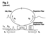
- FIG 2 With a coupler 23 to which are connected an input optical path 22 and an output optical path 24 as well as first and second optical paths respectively 25, 26 forming an optical loop path including a first and a second fiber.
- the first fiber is made of a one kilometer long HNL-fiber with a local dispersion near to Ops/(nm.km).
- the second fiber 26 is made of a 3.35km standard single mode fiber with a dispersion around 17ps/(nm.km).
- the supplied input optical signal E in ( ⁇ S ) at input 22 is equally divided by the coupler 23 into two optical signals E 1 and E 2 propagating clockwise and counterclockwise respectively in the loop optical path formed by the first and second fibers 25, 26.
- a polarization controller not shown on figure 2 is inserted in the DI-NOLM as to select the proper polarization states in this interferometer.
- An Erbium-doped fiber amplifier (also not shown on figure 2) and a dispersion compensation fiber 29 (DCF) are placed before and after the DI-NOLM as to control the input power and to compensate the residual chromatic dispersion, respectively.
- Dispersion-Imbalanced NOLM exploits the strongly enhanced Kerr effect in HNL fibers which induces a phase variation between two pulses propagating in counter direction within the device.
- the asymmetric nature in chromatic dispersion of the DI-NOLM allows a fine control of the amount of phase difference through a control of the launched peak power.
- the DI-NOLM as shown on figure 2 is composed with two types of fibers, a high nonlinear fiber 25 to create a nonlinear phase variation long pulse shape, and a dispersive fiber 26 with large effective area.
- Latter induces a temporal broadening ending up into an optical peak power decrease.
- the optical field E 1 is directly launched into a HNL-fiber (with its maximum peak power), contrary at optical field E 2 which is firstly broaden inside dispersive fiber 26.
- the nonlinear phase accumulated by E 2 in the HNL is very low with respect to that of optical field E,.
- a DI-NOLM comprising an optical loop made of two spools of dispersive fibers with large effective area but of local dispersion of opposite sign as well as a HLN fiber in between.
- the input optical signal needs to be initially chirped either using an additional stage or by placing the apparatus at a given location in the dispersion-managed transmission line.
- incoming pulses are either temporarily compressed or broadened depending of the sign of the local dispersion in the two arms of the optical loop of the DI-NOLM. Then, a nonlinear phase shift is generated between both counterpropagating optical fields inside the HNL as the consequence of the peak power imbalance.
- DI-NOLM transfer function Transmittance
- ⁇ is the coupling ratio
- ⁇ the nonlinear phase shift
- a transmittance defined by such equation is compatible with an optical power limiter function (for "1" symbols) which can be obtained for a nonlinear phase shift slightly greater than ⁇ .
- an optical power limiter function for "1" symbols
- a saturable absorber-like transfer function of the DI-NOLM is obtained for low nonlinear phase shift.
- Such saturable absorber and optical power limiting functions can be advantageously used to improve RZ-DPSK (but also RZ-On-Off-Keying) transmission system.
- RZ-DPSK modulation format and since the data are phase-coded, an interferometer (Mach-Zehnder) is required at the receiver side, as to recover the information in the amplitude domain.
- an interferometer Machine-Zehnder
- the quality of received and amplitude-translated information strongly depends upon the amplitude variations of the RZ-DPSK optical data stream, which can be efficiently reduced when implementing DI-NOLM in the transmission line ⁇ hence ensuring also a significantly-improved system performance-.
- FIG 3 is shown a dispersion imbalanced nonlinear optical loop mirror according to the invention. It comprises a coupler 23 to which are connected an input path 22 and an output path 24 for optical signal.
- the optical loop path is made according to the invention of the first 30 and second 32 optical path including a first and a second fibers having different properties as to transmitted optical signals. These first and second fibers show large effective areas with local dispersion of opposite sign. Therefore the optical field E 1 launched into the first optical path 30 with i.e.
- the nonlinear loop mirror according to the invention comprises a further optical fiber 31 with a highly nonlinear property and almost no dispersion at least for the applied optical signal.
- the further optical fiber 31 is part of that optical loop and directionally coupled to said first and second optical paths respectively 30, 32. Inside that HNL fiber 31 is generated a nonlinear phase shift between both counterpropagating optical fields E 1 and E 2 as a consequence of the optical peak power imbalance.
- this DI-NOLM With an appropriate design (depending of the location in the transmission line) of this DI-NOLM according to the invention, it will be possible to treat i.e. regenerate optical signals made of RZ or RZ/DPSK, even with peaks possibly of a shape at halfway taking more than 65% of bit time, e.g. 66%.
- the treatment of such kind of signals using the method according to the invention will be possible without any alteration of the optical regeneration.
- the proposed DI-NOLM based all optical regenerator allows among others RZ/DPSK regeneration at ultra-high bit rate. Furthermore, since the device uses the ultra-fast Kerr effect in optical fibers, its speed operation potential is well beyond 100 Gbit/s.
- the new implementation of DI-NOLM as proposed is compatible with 50% RZ or 50% RZ/DPSK modulation format i.e. for easy to generate pulses. With such configuration or method, it is not necessary to use a pulse compression stage before the loop mirror, hence reducing the complexity and cost of this solution. Moreover, when using such implementation, intersymbol interference induced by temporal pulse broadening is also reduced.
- Such DI-NOLM as proposed can simultaneously regenerate wavelength division multiplexing WDM channels within the same device.
Landscapes
- Physics & Mathematics (AREA)
- Electromagnetism (AREA)
- Engineering & Computer Science (AREA)
- Computer Networks & Wireless Communication (AREA)
- Signal Processing (AREA)
- Optical Modulation, Optical Deflection, Nonlinear Optics, Optical Demodulation, Optical Logic Elements (AREA)
- Optical Communication System (AREA)
Priority Applications (3)
| Application Number | Priority Date | Filing Date | Title |
|---|---|---|---|
| EP04290304A EP1562314A1 (fr) | 2004-02-05 | 2004-02-05 | Régénérateur de signaux optiques pour des signaux RZ à haut débit |
| US11/002,139 US20050180758A1 (en) | 2004-02-05 | 2004-12-03 | Optical regenerator for high bit rate return-to-zero transmission |
| CN200410101771.6A CN1652006A (zh) | 2004-02-05 | 2004-12-22 | 用于高比特率归零传输的光再生器 |
Applications Claiming Priority (1)
| Application Number | Priority Date | Filing Date | Title |
|---|---|---|---|
| EP04290304A EP1562314A1 (fr) | 2004-02-05 | 2004-02-05 | Régénérateur de signaux optiques pour des signaux RZ à haut débit |
Publications (1)
| Publication Number | Publication Date |
|---|---|
| EP1562314A1 true EP1562314A1 (fr) | 2005-08-10 |
Family
ID=34673747
Family Applications (1)
| Application Number | Title | Priority Date | Filing Date |
|---|---|---|---|
| EP04290304A Withdrawn EP1562314A1 (fr) | 2004-02-05 | 2004-02-05 | Régénérateur de signaux optiques pour des signaux RZ à haut débit |
Country Status (3)
| Country | Link |
|---|---|
| US (1) | US20050180758A1 (fr) |
| EP (1) | EP1562314A1 (fr) |
| CN (1) | CN1652006A (fr) |
Families Citing this family (7)
| Publication number | Priority date | Publication date | Assignee | Title |
|---|---|---|---|---|
| US7590358B2 (en) * | 2005-02-28 | 2009-09-15 | Vladimir Grigoryan | Optical regenerative amplifier for binary phase shift-keying signals |
| ITMI20051802A1 (it) | 2005-09-28 | 2007-03-29 | Marconi Comm Spa | Schema di ricevitore ottico con prestazioni migliorate ed elemento decisore tutto ottico |
| CN101277155A (zh) * | 2007-03-30 | 2008-10-01 | 华为技术有限公司 | 一种色散补偿信号的产生装置与方法 |
| WO2009047856A1 (fr) * | 2007-10-11 | 2009-04-16 | Fujitsu Limited | Générateur d'impulsions optiques et processeur de signal optique |
| CN109889360B (zh) * | 2018-12-07 | 2022-04-05 | 中国南方电网有限责任公司 | 确定再生器放置位置的方法及装置 |
| CN112564809B (zh) * | 2021-02-22 | 2021-05-11 | 南京信息工程大学 | 一种基于环路合并的少模全光再生装置及方法 |
| CN113804402B (zh) * | 2021-07-20 | 2023-11-10 | 广东工业大学 | 一种基于环行光路的光纤微量色散高精度测量装置及方法 |
Citations (3)
| Publication number | Priority date | Publication date | Assignee | Title |
|---|---|---|---|---|
| JP2000214499A (ja) * | 1999-01-25 | 2000-08-04 | Nippon Telegr & Teleph Corp <Ntt> | 光パルス圧縮器 |
| WO2001078264A2 (fr) * | 2000-02-14 | 2001-10-18 | Xtera Communications, Inc. | Amplificateur de rapport signal/bruit (rsb) pour systemes de multiplexage en longueur d'ondes |
| EP1227363A2 (fr) * | 2001-01-30 | 2002-07-31 | The Furukawa Electric Co., Ltd. | Dispositif à mirroir optique en boucle non-linéaire |
Family Cites Families (4)
| Publication number | Priority date | Publication date | Assignee | Title |
|---|---|---|---|---|
| US6760148B2 (en) * | 1998-03-24 | 2004-07-06 | Xtera Communications, Inc. | Nonlinear polarization amplifiers in nonzero dispersion shifted fiber |
| KR100350232B1 (ko) * | 2000-09-21 | 2002-08-27 | 광주과학기술원 | 비대칭 비선형 광섬유 거울을 이용한 8자형 광섬유 펄스레이저 |
| US6587606B1 (en) * | 2000-10-20 | 2003-07-01 | Corning Incorporated | Waveguide fiber dispersion compensating regenerator |
| JP4472222B2 (ja) * | 2001-09-28 | 2010-06-02 | 富士通株式会社 | 信号光を波形整形するための方法、装置及びシステム |
-
2004
- 2004-02-05 EP EP04290304A patent/EP1562314A1/fr not_active Withdrawn
- 2004-12-03 US US11/002,139 patent/US20050180758A1/en not_active Abandoned
- 2004-12-22 CN CN200410101771.6A patent/CN1652006A/zh active Pending
Patent Citations (3)
| Publication number | Priority date | Publication date | Assignee | Title |
|---|---|---|---|---|
| JP2000214499A (ja) * | 1999-01-25 | 2000-08-04 | Nippon Telegr & Teleph Corp <Ntt> | 光パルス圧縮器 |
| WO2001078264A2 (fr) * | 2000-02-14 | 2001-10-18 | Xtera Communications, Inc. | Amplificateur de rapport signal/bruit (rsb) pour systemes de multiplexage en longueur d'ondes |
| EP1227363A2 (fr) * | 2001-01-30 | 2002-07-31 | The Furukawa Electric Co., Ltd. | Dispositif à mirroir optique en boucle non-linéaire |
Also Published As
| Publication number | Publication date |
|---|---|
| CN1652006A (zh) | 2005-08-10 |
| US20050180758A1 (en) | 2005-08-18 |
Similar Documents
| Publication | Publication Date | Title |
|---|---|---|
| EP1130456B1 (fr) | Méthode, dispositif et système de mise en forme d'ondes du signal optique | |
| JP3920297B2 (ja) | 光スイッチおよび光スイッチを利用した光波形モニタ装置 | |
| JP5246217B2 (ja) | 光スイッチおよび光スイッチを利用した光波形モニタ装置 | |
| US5532868A (en) | Apparatus and method for compensating chromatic dispersion produced in optical phase conjugation or other types of optical signal conversion | |
| EP1378789B1 (fr) | Procédé et dispositif pour la génération d'un signal optique à spectre élargi | |
| JP4472222B2 (ja) | 信号光を波形整形するための方法、装置及びシステム | |
| Bogoni et al. | All-optical regeneration and demultiplexing for 160-Gb/s transmission systems using a NOLM-based three-stage scheme | |
| US20040061922A1 (en) | Variable duty cycle optical pulses | |
| US5757529A (en) | In-line regenerating apparatus for regenerating a soliton-conveyed signal by synchronously modulating the solitons by means of a non-linear optical loop mirror | |
| JP4574629B2 (ja) | 光スイッチおよび光スイッチを利用した光波形モニタ装置 | |
| Miyakawa et al. | 2.56 Tbit/s (40Gbit/s× 64WDM) Unrepeatered 230km Transmission with 0.8 bit/s/Hz Spectral Efficiency Using Low-Noise Fiber Raman Amplifier and 170µm-Aeff Fiber | |
| EP1562314A1 (fr) | Régénérateur de signaux optiques pour des signaux RZ à haut débit | |
| Suzuki et al. | All-optical regenerator using wavelength shift induced by cross-phase modulation in highly nonlinear dispersion-shifted fiber | |
| Seguineau et al. | Experimental demonstration of simple NOLM-based 2R regenerator for 42.66 Gbit/s WDM long-haul transmissions | |
| JP4629642B2 (ja) | 光スイッチおよび光スイッチを利用した光波形モニタ装置 | |
| Bhatia et al. | Comparative investigations of DWDM transmission system with PMD for different orthogonally modulated signals at 80 Gb/s | |
| Futami et al. | All-optical amplitude noise suppression of 160-Gb/s OOK and DPSK data signals using a parametric fiber switch | |
| JP3219121B2 (ja) | ダーク光ソリトンの伝送方法 | |
| Chong et al. | Optical 3R regeneration for 10 synchronous channels using self-phase modulation in a bidirectional fiber configuration | |
| Roethlingshoefer et al. | Phase-preserving amplitude regeneration using dispersion-imbalanced loop mirror | |
| JP4155283B2 (ja) | 光伝送路 | |
| Chayet et al. | Compensation of chromatic dispersion by chirp control in all-optical regenerator based on asymmetric Sagnac loop | |
| Zhu et al. | 43 Gb/s 264 km field fiber transmission using 2R regeneration in a tunable all-optical signal regenerator | |
| Tan et al. | Pulsewidth tunable NRZ-to-RZ data format conversion by combination of SOA-and fiber-based switches | |
| Yu et al. | Simultaneous all-optical demultiplexing and regeneration of channel from 40 Gbit/s OTDM signals based on SPM and XPM in dispersion-shifted fibre |
Legal Events
| Date | Code | Title | Description |
|---|---|---|---|
| PUAI | Public reference made under article 153(3) epc to a published international application that has entered the european phase |
Free format text: ORIGINAL CODE: 0009012 |
|
| 17P | Request for examination filed |
Effective date: 20040902 |
|
| AK | Designated contracting states |
Kind code of ref document: A1 Designated state(s): AT BE BG CH CY CZ DE DK EE ES FI FR GB GR HU IE IT LI LU MC NL PT RO SE SI SK TR |
|
| AX | Request for extension of the european patent |
Extension state: AL LT LV MK |
|
| AKX | Designation fees paid |
Designated state(s): AT BE BG CH CY CZ DE DK EE ES FI FR GB GR HU IE IT LI LU MC NL PT RO SE SI SK TR |
|
| RAP1 | Party data changed (applicant data changed or rights of an application transferred) |
Owner name: ALCATEL LUCENT |
|
| 17Q | First examination report despatched |
Effective date: 20100223 |
|
| STAA | Information on the status of an ep patent application or granted ep patent |
Free format text: STATUS: THE APPLICATION IS DEEMED TO BE WITHDRAWN |
|
| 18D | Application deemed to be withdrawn |
Effective date: 20100706 |