EP1563712B1 - Set und verfahren für die herstellung eines hörgerätes sowie nach dem verfahren hergestelltes hörgerät - Google Patents
Set und verfahren für die herstellung eines hörgerätes sowie nach dem verfahren hergestelltes hörgerät Download PDFInfo
- Publication number
- EP1563712B1 EP1563712B1 EP03810932A EP03810932A EP1563712B1 EP 1563712 B1 EP1563712 B1 EP 1563712B1 EP 03810932 A EP03810932 A EP 03810932A EP 03810932 A EP03810932 A EP 03810932A EP 1563712 B1 EP1563712 B1 EP 1563712B1
- Authority
- EP
- European Patent Office
- Prior art keywords
- casting
- casting space
- hearing aid
- space element
- channel
- Prior art date
- Legal status (The legal status is an assumption and is not a legal conclusion. Google has not performed a legal analysis and makes no representation as to the accuracy of the status listed.)
- Expired - Lifetime
Links
Images


Classifications
-
- H—ELECTRICITY
- H04—ELECTRIC COMMUNICATION TECHNIQUE
- H04R—LOUDSPEAKERS, MICROPHONES, GRAMOPHONE PICK-UPS OR LIKE ACOUSTIC ELECTROMECHANICAL TRANSDUCERS; ELECTRIC HEARING AIDS; PUBLIC ADDRESS SYSTEMS
- H04R25/00—Electric hearing aids
- H04R25/60—Mounting or interconnection of hearing aid parts, e.g. inside tips, housings or to ossicles
-
- H—ELECTRICITY
- H04—ELECTRIC COMMUNICATION TECHNIQUE
- H04R—LOUDSPEAKERS, MICROPHONES, GRAMOPHONE PICK-UPS OR LIKE ACOUSTIC ELECTROMECHANICAL TRANSDUCERS; ELECTRIC HEARING AIDS; PUBLIC ADDRESS SYSTEMS
- H04R25/00—Electric hearing aids
- H04R25/65—Housing parts, e.g. shells, tips or moulds, or their manufacture
- H04R25/658—Manufacture of housing parts
-
- H—ELECTRICITY
- H04—ELECTRIC COMMUNICATION TECHNIQUE
- H04R—LOUDSPEAKERS, MICROPHONES, GRAMOPHONE PICK-UPS OR LIKE ACOUSTIC ELECTROMECHANICAL TRANSDUCERS; ELECTRIC HEARING AIDS; PUBLIC ADDRESS SYSTEMS
- H04R25/00—Electric hearing aids
- H04R25/65—Housing parts, e.g. shells, tips or moulds, or their manufacture
- H04R25/652—Ear tips; Ear moulds
Definitions
- the invention is in the field of hearing aids and relates to a set, a method and a hearing aid according to the preambles of the corresponding independent claims.
- Set and method according to the invention are used for the production of the hearing aid.
- the hearing aid belongs to the category of hearing aids that are at least partially worn in the ear canal, which have a casting cavity in a provisional state and which are adapted to this auditory canal by pouring the casting cavity into an auditory canal.
- the hearing aid according to the invention has a cast molded body which is precisely adapted to the auditory canal of a wearer.
- the hearing aid according to the invention is preferably a hearing aid, a radio receiver or a device with a different acoustic function.
- the hearing aid according to the invention can also have only one protective function, that is to say it can be, for example, a protective plug against noise or water.
- Hearing aids of the type mentioned are described for example in the publications EP-0821541 (or US-6249587), EP-0821542 (or US-6097826) or EP-0821543 (or US-6052473).
- the hearing aids described in these publications have a stretchable membrane which extends over the lateral surface of the device and on an outer end plate and on the inner end side forming speakers or attached to a speaker holding ring.
- the faceplate, membrane and loudspeaker essentially delimit the casting cavity or the molding molded therein.
- the electronic components of the device are at least partially poured into the molded body quasi-floating, such that their relative positions are also adapted to a certain extent to the shape of the individual auditory canal.
- a pouring template equipped for supplying the casting material and the venting of the casting cavity is placed on the end plate, and optionally a positioning attachment for the exact positioning of the innermost part of the hearing device in the auditory canal on the inner end face.
- the casting template and the positioning attachment are removed, as a result of which the hearing aid is essentially completed and can be worn immediately.
- the problems which must be solved in particular in the development of said type of hearing aids are problems of miniaturization (in particular for appliances to be worn entirely in the ear canal, which have a diameter of less than 12 mm and a length of less than 25 mm) and Problems of safety of the casting process that should be practicable in the ear canal of the person who will be wearing the device (wearer).
- the device should be in a substantially load-bearing condition, such that it can be handed over to the wearer without further processing or at most after a few simple manipulations.
- it should also be able to meet conditions regarding functional adaptation to the needs of the wearer it should offer a high level of comfort and it should be able to be produced in an economically responsible framework.
- the mentioned problems and wishes are addressed or fulfilled with the hearing aids according to the state of the art in various ways.
- the devices according to the publications mentioned above meet the requirements of miniaturization, the minimal rework and the comfort.
- the GiePrint in the distal (inner) area of the device is satisfactory.
- the electronic components must be manipulated to fit the ear canal and are exposed to the casting process, which can damage them.
- the molded body and the electronic components are firmly connected together in the finished device. In other words, if an electronic part is damaged by the casting process, if a faulty molding is cast in a casting process or if it is determined on the finished device that the selected electronics are not optimal for the wearer, the entire hearing aid must be replaced. The device can not be repaired. All of this has an economic burden.
- the invention now has the object of providing a hearing aid to be worn at least partially in the auditory canal, which in a provisional state has a casting cavity and, in a definite state adapted to a specific auditory canal, a molded body having an individual shape cast in the casting cavity.
- the hearing aid is intended to meet the abovementioned requirements with regard to miniaturization, safety, immediate availability, functional adaptability, wearing comfort, reparability and economy at least as well or better than known hearing aids of the same type. Furthermore, it is the object of the invention to provide a set and a method for producing the hearing device.
- the hearing aid according to the invention consists in its provisional state of two or three elements (central and outer Giessraumelement and optionally separate channel element). In this state, it has no components serving the acoustic function (in particular no electronic components).
- the two or three elements are connected by simply detachable connections, in particular positive snap connections. They define the casting cavity, give the provisional device sufficient stability for insertion into the ear canal, and are at least partially plastically deformable (bendable) for a first rough adaptation to the auditory canal.
- the outer casting chamber element and optionally the separate channel element are removed from the molded body cast in the casting cavity, wherein the outer casting chamber element is replaced by a standardized, possibly limitedly deformable, electronic module.
- the electronic module is attached using the same, releasable connection to the molding, as the remote, outer casting chamber element.
- the hearing aid is not to be equipped for an acoustic function
- another module takes the place of the electronic module, which has essentially the same shape as the electronic module, but which serves, for example, a passive protective function and is equipped accordingly.
- the central G manraumelement has an inner and an outer ring, which are interconnected by a tubular, expandable membrane.
- the diaphragm forms a surface of the device that can be adapted to an ear canal thanks to its expansibility, and the two rings essentially determine the shape of the inner and outer faces of the device.
- the outer casting chamber element is matched in its shape to the outer ring of the central casting space element. It holds in the casting room essentially free the space for the electronic module and has an opening (pouring opening) for pressing the casting material and optionally a vent opening.
- an at least partially bendable channel element is provided which extends in the preliminary device from the inside of the outer Giessraum institutes to the inner ring of the central Giessraumiatas.
- the channel element is detachably connected in its one end region or firmly connected to the inside of the outer Giessraumiatas and adjusted in its other end to the inner ring of the central Giessraumiatas and advantageously releasably connected thereto, that it closes the opening substantially and limits its axial mobility , Due to the bendability of the channel element, the reserved loudspeaker channel receives a signal to the individual. Auditory canal adapted, possibly curved shape, wherein the adapted (curved) part of the channel in the finished device either between the output side of the speaker and the inner end of the device or between the input side of the speaker and the outer face of the device.
- the electronic module is based on an outer end plate and optionally has a housing, of which the end plate is a part. It contains all the components that serve the acoustic function (eg microphone, amplifier, loudspeaker, receiver coil, battery compartment and corresponding cabling).
- the speaker is housed in the electronics module so that its output side is directed away from the face plate.
- the speaker is disposed on an extension of the electronic module, wherein the extension is bendable such that the orientation of the speaker relative to the rest of the electronic module is variable to a limited extent.
- elastic positive locking means are arranged with the aid of the outer G manraumelement or the electronic module or other module on the central Giessraumelement snaps and also removable again.
- Equally such positive locking means are advantageously provided on the inner ring of the central Giessraumides and on the channel element or on an attachable to the inner end face of the final device cerumen protection cap.
- the main advantages of the hearing aid according to the invention consist in its simple production or individualization and in the fact that the individualized part (only central casting space element with molded body) and the functional part (electronics module) can be assembled and separated again in an extremely simple manner. This makes it possible to replace one or the other part individually, and it is possible to try the hearing aid in its finished form with differently equipped electronic modules and so even better adapted to the wishes and needs of the wearer.
- the hearing aid is repairable and yet adapted not only with respect to the shape of its lateral surface but also with respect to the relative positions of the inner and outer end face of the specific auditory canal.
- Figure 1 shows very schematically the preparation of the hearing aid according to the invention from a set consisting essentially of a central casting space element 1, an outer casting space element 2, a separate channel element 3 and an electronic module 4 or 4 '.
- the casting space elements 1 and 2 and the channel element 3 are shown on the left in FIG. 1 one above the other.
- the tubular membrane 1.1, the outer ring 1.2 and the inner ring 1.3 can be seen on the outer casting space element, the pouring opening 2.1, the vent opening 2.2 and a connecting means 2.3 (eg, narrowing towards the inside) at the outer pouring space element 2, at the channel element 3 the middle one bendable part 3.1, the first end region 3.2 (eg elastically compressible head piece) equipped as a connection means to the outer casting space element and the second end region 3.3 (eg end plate or thickening, which is larger than the opening of the end piece) adapted to the inner ring 1.3 of the central casting space element 1 inner ring 1.3 and optionally releasably connected to this).
- the first end region 3.2 eg elastically compressible head piece
- the second end region 3.3 eg end plate or thickening, which is larger than the opening of the end piece
- the second end region 3.3 of the channel element 3 and the inner ring 1.3 of the central casting space element 1 are to be designed such that the end region 3.3 tightly closes the opening of the inner ring 1.3 at least for the intended casting material.
- the hearing aid in its provisional state that is to say the elements 1 to 3 mounted together, is shown in FIG.
- the illustrated hearing aid is already adapted by a corresponding bend of the central part 3.1 of the channel element 3 with respect to the relative position of the inner and the outer end side of the ear canal.
- the outer casting chamber element 2 is positioned on or in the outer ring 1.2 of the central casting space element 1
- the second end region (3.3) of the channel element 3 is positioned on or in the inner ring 1.3
- the first end region 3.2 of the channel element 3 is engaged on the outer casting space element 2 (FIG. positive, releasable snap connection).
- At least the outer ring 1.2 and the outer Giessraumelement 2 further cooperating positive locking means, by means of which the outer G manraumelement 2 is fixed in or on the outer ring 2.1 and optionally also the rotational position of the two elements is defined relative to each other.
- the positive-locking means for such a connection are shown in FIG. 1 as depressions in the ring 1.2 and corresponding projections on the outer casting-space element 2, wherein projections and depressions are dimensioned such that they form a snap-fit closure.
- Corresponding connection means can also be provided between the inner ring 1.3 and the second end region 3.3 of the channel element 3. Such a connection can be designed such that it is tight for the casting material. Further measures to increase this tightness are described below in connection with FIG.
- the hearing aid is positioned in its preliminary state in the ear canal of a patient.
- a pouring opening 2.1 a not shown in a suitable manner Press connected with a casting material in the casting cavity 5 is pressed.
- a kind of standpipe is advantageously arranged at the vent 2.2, in which the casting material rises when the G confuseshohlraum 5 is completely filled and in which the rise height of the casting material can be read as an indication of the casting pressure. It is also possible to omit the vent 2.2 and according to the connection between the outer ring 1.2 and outer casting element 2 air-permeable but dense to design for the casting material.
- the outer casting space element 2 and the channel element 3 are removed. It remains the individualized part of the hearing aid, which consists only of the molded body molding 7 and the central casting chamber 3.
- the electronics module 4 or 4 ' is mounted to complete the hearing aid, for example by means of a connection which is identical to the connection with the outer casting space element 2 (for example elastic snap connection).
- the electronics module 4 or 4 ' has, for example, a battery compartment 4.1 with a battery, a microphone 4.2 directed towards the outer front side, an amplifier chip 4.3 and a loudspeaker 4.4 directed against the inner front side, and the corresponding wiring (not shown).
- the loudspeaker 4.4 is tinted, either rigidly integrated in the electronic module (module 4) or arranged in a loudspeaker extension 4.5 (module 4 '), wherein the loudspeaker extension 4.5 can be aligned differently by bending over the rest of the module.
- a protection module must be like the electronic module 4 or 4 'on the outer ring 1.2, for example, snapped and it must seal the speaker channel 8 to the outside.
- the other module must therefore have substantially the same shape on its side facing the cast molded body 7 as one or the other of the electronic modules 4 or 4 'shown in FIG.
- the outer casting space element 2 and the channel element 3 are removed, the outer casting space element is replaced by the electronic module.
- the device 6 has a loudspeaker 4.4, which is rigidly integrated in the electronics module 4, and a loudspeaker channel 8 extending between the inner end surface and the output side of the loudspeaker 4.4, which has a bend which is adapted to the individual auditory canal.
- the device 6 ' also has an individually curved loudspeaker channel 8, into which the corresponding curved loudspeaker extension 4.5 of the electronic module 4' is inserted, such that the output side of the loudspeaker 4.4 is positioned as close as possible to the eardrum.
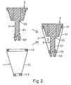
- FIG. 2 shows another exemplary embodiment of the hearing aid according to the invention in the same way as FIG. 1 (left part).
- the elements of the hearing aid are shown in its provisional state, individually (left) and assembled together (right).
- Identical elements are designated by the same reference numerals as in FIG. 1.
- FIG. 2 in which the device in its preliminary form consists of three elements, there are only two elements: a central casting space element 1 and an outer casting space element 2.
- the channel element 3 is fixedly connected in its first end region 3.2 to the outer casting chamber element 2 and has in its second end region 3.3 a to the inner ring 1.3 of the central casting chamber 1 adapted shape such that this end region closes the opening of the ring 1.3 and the ring 1.3 limited in an axial position (definition of the axial length of the device in its definitive form).
- the second end region 3.3 of the channel element is, for example, as shown, a compressible thickening which can be snapped into the ring 1.3, wherein a movement of the ring 1.3 against the outer casting chamber element 2 can be prevented by a further internal thickening. If no other precautions are taken to seal the Giessholraumes, the snap connection between the channel element 3 and inner ring 1.3 for this seal must be designed accordingly.
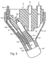
- FIG. 3 shows in a partially cut-away, three-dimensional representation a further, exemplary embodiment of the hearing aid according to the invention in its provisional state.
- the device is of the same type as the device according to FIG. 1.
- the same parts are designated by the same reference numerals as in FIGS. 1 and 2.
- the device according to FIG. 3 has a double channel element, wherein the loudspeaker channel Part (3.1 / 2) is executed, as shown in the figure 1, and the further part (Ventkanalteil 3.4, also at least partially bendable) is used to keep free a Ventkanales.
- the second end region 3.3 serves both Kalnalelement turnover.
- a corresponding opening is provided in the outer G manraumelement 2 (and correspondingly in the electronic module) or in the outer ring 1.2 and in the inner ring 1.3.
- the central Giessraumelement 1 for receiving the two channel element parts 3.1 / 2 and 3.4 each have a hose 1.4 and 1.5. These are attached to the inner ring 1.3 and have a length which is slightly larger than the corresponding distance to the outer Giessraumelement.
- the hoses 1.4 and 1.5 also make it possible not to form the two channel element parts 3.1 / 2 and 3.4 as shown in Figure 1 bar-shaped but in the form of disk columns. This shape allows a strong bending of the extensions without cross-sectional change of the channel to be kept free.
- hoses 1.4 and 1.5 cause the speaker and the vent channel to be at a minimum distance from the shell surface of the device (in its definitive state) at any point.
- the central casting space element 1 of the embodiment of the hearing aid according to the invention must have different material properties at different locations.
- the membrane 1.1 must be highly ductile.
- the outer ring 1.2 and the inner ring 1.3 must be elastic and dimensionally stable.
- the hoses 1.4 and 1.5 must be bendable. It turns out that such a central casting space element 1 is advantageously produced by means of injection molding technology from, for example, three different materials, such that the individual regions are cast together and the Giessraumelement after the last casting step can be removed as a whole from the injection mold.
- the casting material for casting the molding is adapted to the material of the membrane and the hoses so that the two materials form a compound.
- the casting composition is advantageously a cold crosslinking agent Silicone material.
- the Giessmass but can also be a polyurethane or other, as fast as possible curable material.
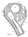
- FIG. 4 shows the hearing aid according to FIG. 3 in its definitive state.
- the electronic module 4 is snapped in place of the outer Giessraumiatas in the outer ring 1.2.
- the electronic module 4 and the outer casting chamber element are matched to one another in such a way that the output side of the loudspeaker 4.4 is directed into the hose 1.4 in the snap-in electronic module.
- the vent channel 9 kept free by the vent channel part 3.4 of the channel element 3 and the tube 1.5 extends axially through the entire device.
- a wax protection cap 10 adapted in shape to the second end region of the channel element can be placed in the area of the inner end face of the hearing aid according to FIG. 4, a wax protection cap 10 adapted in shape to the second end region of the channel element can be placed.
- corresponding connecting means are provided for this purpose on the inner ring 1.3 of the central casting chamber element 1, by means of which also the said end region of the channel element can be fastened to the inner ring 1.3.
- FIG. 5 shows a further, exemplary embodiment of the hearing aid according to the invention in its provisional state, ie with a casting cavity 5.
- This device differs from the device according to FIGS. 3 and 4 in that the part of the loudspeaker channel 8 facing the inner device side is adapted to the loudspeaker is, that is in particular not bent.
- This is realized with a loudspeaker channel part of the channel element 3, the central region 3.1 of which is not deformable at the corresponding point, but rather on a point facing the outer casting space element 2.
- FIG. 6 shows an electronic module 4 'which can be used after the casting process in the hearing device according to FIG.
- the loudspeaker of this electronics module 4 ' is arranged at the distal end of a loudspeaker extension 4.5 whose proximal region is bendable like the corresponding parts of the channel element 3.
- the loudspeaker 4.4 of the electronic module 4 'inserted in the individualized part is positioned in the loudspeaker channel kept free from the loudspeaker channel part 3.1 / 2 and from the hose 1.4, its output side being in the Regions of the inner ring 1.3 is positioned.
Landscapes
- Engineering & Computer Science (AREA)
- Physics & Mathematics (AREA)
- Health & Medical Sciences (AREA)
- General Health & Medical Sciences (AREA)
- Neurosurgery (AREA)
- Otolaryngology (AREA)
- Manufacturing & Machinery (AREA)
- Acoustics & Sound (AREA)
- Signal Processing (AREA)
- Headphones And Earphones (AREA)
- Details Of Audible-Bandwidth Transducers (AREA)
- Moulding By Coating Moulds (AREA)
- Audible-Bandwidth Dynamoelectric Transducers Other Than Pickups (AREA)
- Thermistors And Varistors (AREA)
Description
- Die Erfindung liegt auf dem Gebiete der Hörgeräte und betrifft ein Set, ein Verfahren und ein Hörgerät nach den Oberbegriffen der entsprechenden, unabhängigen Patentansprüche. Set und Verfahren gemäss Erfindung dienen für die Herstellung des Hörgerätes. Das Hörgerät gehört zur Gattung der Hörgeräte, die mindestens teilweise im Gehörgang getragen werden, die in einem vorläufigen Zustand einen Giesshohlraum aufweisen und die durch Ausgiessen des Giesshohlraumes in einem Gehörgang an diesen Gehörgang angepasst werden. Das erfindungsgemässe Hörgerät weist also in seinem definitiven Zustand einen genau an den Gehörgang eines Trägers angepassten, gegossenen Formkörper auf. Das erfindungsgemässe Hörgerät ist vorzugsweise eine Hörhilfe, ein Funkempfangsgerät oder ein Gerät mit einer anderen akustischen Funktion. Das erfindungsgemässe Hörgerät kann aber auch nur eine Schutzfunktion haben, das heisst es kann beispielsweise ein Schutzpfropfen gegen Lärm oder Wasser sein.
- Hörgeräte der genannten Art sind beispielsweise beschrieben in den Publikationen EP-0821541 (oder US-6249587), EP-0821542 (oder US-6097826) oder EP-0821543 (oder US-6052473). Die in diesen Publikationen beschriebenen Hörgeräte weisen eine dehnbare Membran auf, die sich über die Mantelfläche des Gerätes erstreckt und die an einer äusseren Stirnplatte und am die innere Stirnseite bildenden Lautsprecher oder an einem den Lautsprecher haltenden Ring befestigt ist. Stirnplatte, Membran und Lautsprecher begrenzen im wesentlichen den Giesshohlraum bzw. den darin gegossenen Formkörper. Die elektronischen Bestandteile des Gerätes werden mindestens teilweise im Formkörper quasi schwimmend eingegossen, derart, dass ihre relativen Positionen zu einem gewissen Grade ebenfalls an die Form des individuellen Gehörganges angepasst werden. Für den Giessvorgang wird auf der Stirnplatte eine für das Zuführen der Giessmasse und die Entlüftung des Giesshohlraumes ausgestattete Giessschablone und auf der inneren Stirnseite gegebenenfalls ein Positionieraufsatz für die exakte Positionierung des innersten Teils des Hörgerätes im Gehörgang aufgesetzt. Nach dem Giessvorgang werden Giessschablone und Positionieraufsatz entfernt, wodurch das Hörgerät im wesentlichen fertiggestellt und sofort tragbar ist.
- Die Probleme, die bei der Entwicklung der genannten Art von Hörgeräten insbesondere gelöst werden müssen, sind Probleme der Miniaturisierung (insbesondere für ganz im Gehörgang zu tragende Geräte, die einen Durchmesser von weniger als 12 mm und eine Länge von weniger als 25 mm aufweisen) und Probleme der Sicherheit des Giessvorgangs, der im Gehörgang der Person, die das Gerät tragen wird (Träger), durchführbar sein soll. Ferner sollte das Gerät nach dem Giessvorgang in einem im wesentlichen tragfertigen Zustand sein, derart, dass es ohne weitere Bearbeitung oder höchstens nach einigen wenigen, einfachen Handgriffen dem Träger übergeben werden kann. Trotzdem soll es auch Bedingungen bezüglich funktionsmässige Anpassung an die Bedürfnisse des Trägers erfüllen können, es soll einen hohen Tragkomfort bieten und es soll in einem ökonomisch verantwortbaren Rahmen herstellbar sein.
- Die genannten Probleme und Wünsche werden mit den Hörgeräten gemäss dem Stande der Technik in verschiedener Weise angegangen bzw. erfüllt. Die Geräte gemäss den oben genannten Publikationen erfüllen die Anforderungen der Miniaturisierung, der minimalen Nachberarbeitung und des Tragkomforts ausgezeichnet. Die Giesssicherheit im distalen (inneren) Bereich des Gerätes ist befriedigend. Die elektronischen Bestandteile müssen für die Anpassung an den Gehörgang manipuliert werden und sind dem Giessvorgang ausgesetzt, wodurch sie beschädigt werden können. Der gegossene Formkörper und die elektronischen Bestandteile sind im fertiggestellten Gerät fest miteinander verbunden. Das heisst mit anderen Worten, wenn ein Elektronikteil durch den Giessvorgang beschädigt wird, wenn in einem Giessvorgang ein fehlerhafter Formkörper gegossen wird oder wenn am fertigen Gerät festgestellt wird, dass die ausgwählte Elektronik nicht optimal für den Träger ist, muss das ganze Hörgerät ersetzt werden. Das Gerät kann nicht repariert werden. All dies wirkt ökonomisch belastend.
- Die Erfindung stellt sich nun die Aufgabe, ein mindestens teilweise im Gehörgang zu tragendes Hörgerät zu schaffen, das in einem vorläufigen Zustand einen Giesshohlraum und in einem definitiven, an einen spezifischen Gehörgang angepassten Zustand einen im Giesshohlraum gegossenen Formkörper mit einer individuellen Form aufweist. Das Hörgerät soll den oben angesprochenen Anforderungen bezüglich Miniatunsierung, Sicherheit, unmittelbarer Verfügbarkeit, funktioneller Anpassbarkeit, Tragkomfort, Reparierbarkeit und Ökonomie mindestens so gut oder besser genügen können als bekannte Hörgeräte derselben Gattung. Ferner ist es die Aufgabe der Erfindung, ein Set und ein Verfahren zur Herstellung des Hörgeräts zu schaffen.
- Diese Aufgaben werden gelöst durch das Set, das Verfahren und das nach dem Verfahren aus dem Set hergestellte Hörgerät, wie sie in den Patentansprüchen definiert sind.
- Das erfindungsgemässe Hörgerät besteht in seinem vorläufigen Zustand aus zwei oder drei Elementen (zentrales und äusseres Giessraumelement und gegebenenfalls separates Kanalelement). Es weist in diesem Zustand keine der akustischen Funktion dienende (insbesondere keine elektronischen) Bestandteile auf. Die zwei oder drei Elemente sind durch einfach lösbare Verbindungen, insbesondere formschlüssige Schnappverbindungen miteinander verbunden. Sie definieren den Giesshohlraum, verleihen dem vorläufigen Gerät eine genügende Stabilität für die Einführung in den Gehörgang und sind für eine erste grobe Anpassung an den Gehörgang mindestens teilweise plastisch verformbar (biegbar). Von dem im Giesshohlraum gegossenen Formkörper werden das äussere Giessraumelement und gegebenenfalls das separate Kanalelement entfernt, wobei das äussere Giessraumelement durch ein standardisiertes, gegebenenfalls begrenzt deformierbares Elektonikmodul ersetzt wird. Das Elektronikmodul wird dabei mit Hilfe derselben, lösbaren Verbindung am Formkörper befestigt, wie das entfernte, äussere Giessraumelement.
- Soll das Hörgerät nicht für eine akustische Funktion ausgerüstet sein, tritt an die Stelle des Elektronikmoduls ein anderes Modul, das im wesentlichen dieselbe Form aufweist, wie das Elektronikmodul, das aber beispielsweise einer passiven Schutzfunktion dient und entsprechend ausgerüstet ist.
- Das zentrale Giessraumelement weist einen inneren und einen äusseren Ring auf, die durch eine schlauchförmige, dehnbare Membran miteinander verbunden sind. Die Membran bildet eine dank ihrer Dehnbarkeit an einen Gehörkanal anpassbare Mantelfläche des Geräts, die beiden Ringe bestimmen im wesentlichen die Form der inneren und der äusseren Stirnfläche des Geräts.
- Das äussere Giessraumelement ist in seiner Form auf den äusseren Ring des zentralen Giessraumelementes abgestimmt. Es hält im Giessraum im wesentlichen den Platz für das Elektronikmodul frei und weist eine Öffnung (Giessöffnung) zum Einpressen der Giessmasse und gegebenenfalls eine Entlüftungsöffnung auf.
- Zur Freihaltung eines Lautsprecherkanals im gegossenen Formkörper und zur Definition der axialen Länge des Gerätes, ist ein mindestens teilweise biegbares Kanalelement vorgesehen, das sich im vorläufigen Gerät von der Innenseite des äusseren Giessraumelementes zum inneren Ring des zentralen Giessraumelementes erstreckt. Das Kanalelement ist in seinem einen Endbereich lösbar oder fest mit der Innenseite des äusseren Giessraumelementes verbunden und in seinem anderen Endbereich derart an den inneren Ring des zentralen Giessraumelementes angepasst und vorteilhafterweise lösbar mit diesem verbunden, dass es dessen Öffnung im wesentlichen verschliesst und seine axiale Beweglichkeit limitiert. Durch die Biegbarkeit des Kanalelementes erhält der freigehaltene Lautsprecherkanal eine an den individuellen. Gehörgang angepasste, gegebenenfalls gebogene Form, wobei der angepasste (gebogene) Teil des Kanals im fertigen Gerät entweder zwischen der Ausgangsseite des Lautsprechers und der inneren Stirnseite des Gerätes oder zwischen der Eingangsseite des Lautsprechers und der äusseren Stirnseite des Gerätes liegt.
- Das Elektronikmodul basiert auf einer äusseren Stirnplatte und weist gegebenenfalls ein Gehäuse auf, von dem die Stirnplatte ein Teil darstellt. Es beinhaltet alle der akustischen Funktion dienenden Bestandteile (z.B. Mikrophon, Verstärker, Lautsprecher, Empfangsspule, Batteriefach und entsprechende Verkabelung). Der Lautsprecher ist derart im Elektronikmodul untergebracht, dass seine Ausgangsseite von der Stirnplatte weg gerichtet ist. Gegebenenfalls ist der Lautsprecher an einem Fortsatz des Elektronikmoduls angeordnet, wobei der Fortsatz derart biegbar ist, dass die Ausrichtung des Lautsprechers relativ zum Rest des Elektronikmoduls in beschränktem Masse variierbar ist. Anstelle des Elektronikmoduls oder zusätzlich dazu kann ein anderes Modul vorgesehen werden, das anstelle des Elektronikmoduls im gegossenen Formkörper des Gerätes einsetzbar ist und dafür mindestens im Bereiche seiner gegen den Formkörper gerichteten, inneren Seite in seiner Form an das äussere Giessraumelement und gegebenenfalls das Kanalelement angepasst ist.
- Vorteilhafterweise sind am äusseren Ring des zentralen Giessraumelementes sowie am äusseren Giessraumelement bzw. am Elektronikmodul oder anderen Modul kooperierende, elastische Formschlussmittel angeordnet, mit deren Hilfe das äussere Giessraumelement bzw. das Elektronikmodul oder andere Modul am zentralen Giessraumelement einschnappbar und auch wieder entfernbar ist. Ebensolche Formschlussmittel sind vorteilhafterweise am inneren Ring des zentralen Giessraumelementes und am Kanalelement bzw. an einer auf die innere Stirnfläche des definitiven Gerätes aufsetzbaren Cerumenschutz-Kappe vorgesehen.
- Das Set zur Herstellung des Hörgerätes umfasst mindestens die oben beschriebenen zwei oder drei Elemente und das Elektronikmodul oder andere Modul. Das Verfahren zur Herstellung des Hörgerätes aus dem Set wird in den folgenden, sich durch ihre Einfachheit auszeichnenden Schritte durchgeführt:
- zentrales Giessraumelement, äusseres Giessraumelement und gegebenenfalls separates Kanalelement zum vorläufigen Hörgerät kombinieren (zusammenschnappen);
- vorläufiges Hörgerät im Gehörgang des Trägers positionieren und dabei durch Biegen des Kanalelementes bezüglich relativer Position von innerer und äusserer Stirnfläche an den Gehörgang anpassen;
- Giessmasse in den Giesshohlraum pressen und Aushärtung der Giessmasse abwarten;
- Hörgerät mit dem gegossenen Formkörper aus dem Gehörgang entfernen;
- äusseres Giessraumelement und gegebenenfalls separates Kanalelement entfernen und Elektronikmodul oder anderes Modul an die Stelle des äusseren Giessraumelementes setzen (einschnappen), womit des Hörgerät tragbereit ist.
- Die Hauptvorteile des erfindungsgemässen Hörgerätes bestehen in seiner einfachen Herstellung bzw. Individualisierung und darin, dass der individualisierte Teil (nur zentrales Giessraumelement mit gegossenem Formkörper) und der funktionelle Teil (Elektronikmodul) in äusserst einfacher Art und Weise zusammensetzbar und wieder trennbar sind. Dadurch ist es möglich, den einen oder anderen Teil einzeln auszuwechseln, und es wird möglich, das Hörgerät in seiner fertigen Form mit verschieden ausgerüsteten Elektronikmodulen auszuprobieren und so noch besser an die Wünsche und Bedürfnisse des Trägers anzupassen. Das Hörgerät ist reparierbar und trotzdem nicht nur in Bezug auf die Form seiner Mantelfläche sondern auch in Bezug auf die relativen Positionen von innerer und äusserer Stimfläche an den spezifischen Gehörgang angepasst.
- Set und Verfahren gemäss Erfindung sowie verschiedene Ausführungsformen des erfindungsgemässen Hörgerätes werden anband der folgenden Figuren mehr im Detail beschrieben. Dabei zeigen:
- Figur 1
- ein Schema der Herstellung von zwei beispielhaften Ausführungsformen des erfindungsgemässen Hörgerätes aus einem Set mit drei Elementen und einem Elektronikmodul (alle parallel zur Achse geschnitten);
- Figur 2
- ein Schema der Herstellung einer weiteren, beispielhaften Ausführungsformen des erfindungsgemässen Hörgerätes (vorläufiger Zustand) aus einem Set mit zwei Elementen (parallel zur Achse geschnitten);
- Figur 3
- eine weitere, beispielhafte Ausführungsform des erfindungsgemässen Hörgerätes in seinem vorläufigen Zustand (dreidimensionale, teilweise geschnittene Darstellung);
- Figur 4
- das Hörgerät gemäss Figur 3 in seinem definitiven Zustand (Schnitt parallel zur Achse);
- Figur 5
- eine weitere, beispielhafte Ausführungsform des erfindungsgemässen Hörgerätes in seinem vorläufigen Zustand (Schnitt parallel zur Achse);
- Figur 6
- ein beispielhaftes Elektronikmodul für das Hörgerät gemäss Figur 5.
- Figur 1 zeigt sehr schematisch die Herstellung des erfindungsgemässen Hörgerätes aus einem Set, das im wesentlichen aus einem zentralen Giessraumelement 1, einem äusseren Giessraumelement 2, einem separaten Kanalelement 3 und einem Elektronikmodul 4 oder 4' besteht. Die Giessraumelemente 1 und 2 und das Kanalelement 3 sind ganz links in der Figur 1 übereinander dargestellt. Dabei sind am zentralen Giessraumelement die schlauchförmige Membran 1.1, der äussere Ring 1.2 und der innere Ring 1.3 erkennbar, am äusseren Giessraumelement 2 die Giessöffnung 2.1, die Entlüftungsöffnung 2.2 und ein Verbindungsmittel 2.3 (z.B. sich gegen innen verengende Öffnung), am Kanalelement 3 der mittlere, biegbare Teil 3.1, der erste als Verbindungsmittel zum äusseren Giessraumelement ausgerüstete Endbereich 3.2 (z.B. elastisch komprimierbares Kopfstück) und der zweite, an den inneren Ring 1.3 des zentralen Giessraumelementes 1 angepasste Endbereich 3.3 (z.B. Endplatte oder Verdickung, die grösser ist als die Öffnung des inneren Ringes 1.3 und gegebenenfalls lösbar mit dieser verbunden werden kann). Wenn für die Abdichtung des Giesshohlraumes in seinem inneren Bereich keine anderen Massnahmen getroffen werden, sind der zweite Endbereich 3.3 des Kanalelementes 3 und der innere Ring 1.3 des zentralen Giessraumelementes 1 derart auszugestalten, dass der Endbereich 3.3 die Öffnung des inneren Ringes 1.3 mindestens für die vorgesehene Giessmasse dicht abschliesst.
- Rechts von den Elementen 1 bis 3 ist in der Figur 1 das Hörgerät in seinem vorläufigen Zustand, das heisst die zusammen montierten Elemente 1 bis 3 dargestellt. Das dargestellte Hörgerät ist bereits durch eine entsprechende Biegung des zentralen Teils 3.1 des Kanalelementes 3 bezüglich der relativen Lage der inneren und der äusseren Stirnseite an den Gehörgang angepasst. Das äussere Giessraumelement 2 ist auf oder im äusseren Ring 1.2 des zentralen Giessraumelementes 1 positioniert, der zweite Endbereich (3.3) des Kanalelementes 3 ist auf dem oder im inneren Ring 1.3 positioniert und der erste Endbereich 3.2 des Kanalelementes 3 ist am äusseren Giessraumelement 2 eingerastet (formschlüssige, lösbare Schnappverbindung).
- Vorteilhafterweise weisen mindestens der äussere Ring 1.2 und das äussere Giessraumelement 2 weitere kooperierende Formschlussmittel auf, mit deren Hilfe das äussere Giessraumelement 2 im oder am äusseren Ring 2.1 befestigt ist und gegebenenfalls auch die Drehposition der beiden Elemente relativ zueinander definiert ist. Die Formschlussmittel für eine derartige Verbindung sind in der Figur 1 als Vertiefungen im Ring 1.2 und entsprechende Anformungen am äusseren Giessraumelement 2 dargestellt, wobei Anformungen und Vertiefungen derart dimensioniert sind, dass sie einen Schnappverschluss bilden. Entsprechende Verbindungsmittel können auch zwischen dem inneren Ring 1.3 und dem zweiten Endbereich 3.3 des Kanalelementes 3 vorgesehen werden. Eine solche Verbindung kann derart ausgestaltet sein, dass sie für die Giessmasse dicht ist. Weitere Massnahmen zur Erhöhung dieser Dichtigkeit sind weiter unten im Zusammenhang mit der Figur 3 beschrieben.
- Das Hörgerät wird in seinem vorläufigen Zustand im Gehörgang eines Patienten positioniert. An der Giessöffnung 2.1 wird in geeigneter Weise eine nicht dargestellte Presse angeschlossen, mit der eine Giessmasse in den Giesshohlraum 5 gepresst wird. Dabei wird an der Entlüftungsöffnung 2.2 vorteilhafterweise eine Art Steigrohr angeordnet, in das die Giessmasse aufsteigt, wenn der Giesshohlraum 5 ganz gefüllt ist und in dem die Steighöhe der Giessmasse als Indiz für den Giessdruck abgelesen werden kann. Es ist auch möglich, die Entlüftungsöffnung 2.2 wegzulassen und entsprechend die Verbindung zwischen äusserem Ring 1.2 und äusserem Giesselement 2 luftdurchlässig aber dicht für die Giessmasse auszugestalten.
- Nach dem Erstarren der in den Giesshohlraum 5 gepressten Giessmasse werden das äussere Giessraumelement 2 und das Kanalelement 3 entfernt. Es bleibt der individualisierte Teil des Hörgerätes, der nur aus dem gegossenen Formkörper 7 und dem zentralen Giessraumelement 3 besteht. In diesen individualisierten Teil wird zur Fertigstellung der Hörgerätes das Elektronikmodul 4 oder 4' montiert, beispielsweise mittels einer Verbindung, die identisch ist mit der Verbindung mit dem äusseren Giessraumelement 2 (z.B. elastische Schnappverbindung).
- Das Elektronikmodul 4 oder 4' weist beispielsweise ein Batteriefach 4.1 mit Batterie, ein gegen die äussere Stirnseite gerichtetes Mikrophon 4.2, einen Verstärkerchip 4.3 und einen gegen die innere Stirnseite gerichteten Lautsprecher 4.4, sowie die entsprechende Verkabelung (nicht dargestellt) auf. Der Lautsprecher 4.4 ist wie bereits weiter oben angetönt, entweder starr im Elektronikmodul integriert (Modul 4) oder in einem Lautsprecherfortsatz 4.5 (Modul 4') angeordnet, wobei der Lautsprecherfortsatz 4.5 gegenüber dem Rest des Moduls durch Biegen verschieden ausgerichtet werden kann. Wenn ein Elektronikmodul 4' mit Lautsprecherfortsatz 4.5 verwendet wird, ist durch entsprechende Ausgestaltung des Kanalelements 3 dafür zu sorgen, dass ein gegen die innere Stirnseite des Gerätes gerichteter Bereich des freigehaltenen Lautsprecherkanals 8 entsprechend dem Lautsprecher 4.4 geradlinig verläuft. Der entsprechende Bereich des Kanalelementes 3 ist also nicht biegbar.
- Wie bereits weiter oben diskutiert, kann anstelle des Elektronikmoduls 4 oder 4' ein anderes, einer anderen Funktion dienendes Modul, beispielsweise ein Schutzmodul zur Anwendung kommen. Ein solches Schutzmodul muss wie das Elektronikmodul 4 oder 4' am äusseren Ring 1.2 beispielsweise einschnappbar sein und es muss den Lautsprecherkanal 8 gegen aussen abdichten. Das andere Modul muss also auf seiner dem gegossenen Formkörper 7 zugewandten Seite im wesentlichen dieselbe Form aufweisen wie das eine oder andere der in der Figur 1 dargestellten Elektronikmodule 4 oder 4'.
- Ganz rechts in der Figur 1 sind zwei fertige Hörgeräte 6 und 6' dargestellt. Diese weisen einen im Giesshohlraum 5 gegossenen Formkörper 7 auf, dessen Mantelfläche von der Membran 1.1 überspannt und in ihrer Kontur genau an den Gehörgang des Trägers angepasst ist. Das äussere Giessraumelement 2 und das Kanalelement 3 sind entfernt, das äussere Giessraumelement ist durch das Elektronikmodul ersetzt. Das Gerät 6 weist einen im Elektronikmodul 4 starr integrierten Lautsprecher 4.4 und einen sich zwischen der inneren Stirnfläche und der Ausgangsseite des Lautsprechers 4.4 erstreckenden Lautsprecherkanal 8 auf, der eine an den individuellen Gehörgang angepasste Biegung aufweist. Das Gerät 6' weist ebenfalls einen individuell gebogenen Lautsprecherkanal 8 auf, in den der entsprechend gebogene Lautsprecherfortsatz 4.5 des Elektronikmoduls 4' eingeschoben ist, derart, dass die Ausgangsseite des Lautsprechers 4.4 möglichst nahe am Trommelfell positioniert ist.
- Figur 2 zeigt in derselben Art wie Figur 1 (linker Teil) eine weitere, beispielhafte Ausführungsform des erfindungsgemässen Hörgerätes. Insbesondere sind die Elemente des Hörgerätes in seinem vorläufigen Zustand gezeigt und zwar einzeln (links) und in zusammen montiertem Zustand (rechts). Gleiche Elemente sind mit gleichen Bezugsziffern bezeichnet wie in Figur 1. Im Unterschied zur Ausführungsform gemäss Figur 1, in der das Gerät in seiner vorläufigen Form aus drei Elementen besteht, sind es in der Figur 2 nur zwei Elemente: ein zentrales Giessraumelement 1 und ein äusseres Giessraumelement 2.
- Das Kanalelement 3 ist in seinem ersten Endbereich 3.2 fest verbunden am äusseren Giessraumelement 2 angeordnet und weist in seinem zweiten Endbereich 3.3 eine an den inneren Ring 1.3 des zentralen Giessraumelementes 1 derart angepasste Form auf, dass dieser Endbereich die Öffnung des Ringes 1.3 schliesst und den Ring 1.3 in einer axialen Position limitiert (Definition der axialen Länge des Gerätes in seiner definitiven Form). Der zweite Endbereich 3.3 des Kanalelementes ist beispielsweise wie dargestellt eine komprimierbare Verdickung, die in den Ring 1.3 schnappbar ist, wobei durch eine weitere, innere Verdickung eine Bewegung des Ringes 1.3 gegen das äussere Giessraumelement 2 verhindert werden kann. Wenn für die Abdichtung des Giessholraumes keine anderen Vorkehrungen getroffen werden, ist die Schnappverbindung zwischen Kanalelement 3 und innerem Ring 1.3 für diese Dichtung entsprechend auszugestalten.
- Figur 3 zeigt in einer teilweise geschnittenen, dreidimensionalen Darstellung eine weitere, beispielhafte Ausführungsform des erfindungsgemässen Hörgerätes in seinem vorläufigen Zustand. Das Gerät ist vom gleichen Typus wie das Gerät gemäss Figur 1. Gleiche Teile sind mit gleichen Bezugsziffern bezeichnet wie in den Figuren 1 und 2. Im Unterschied zum Gerät gemäss Figur 1 weist das Gerät gemäss Figur 3 ein doppeltes Kanalelement auf, wobei der Lautsprecherkanal-Teil (3.1/2) ausgeführt ist, wie dies in der Figur 1 dargestellt ist, und der weitere Teil (Ventkanalteil 3.4, ebenfalls mindestens teilweise biegbar) der Freihaltung eines Ventkanales dient. Der zweite Endbereich 3.3 dient beiden Kalnalelementteilen. Für den Ventkanalteil 3.4 ist im äusseren Giessraumelement 2 (und entsprechend im Elektronikmodul) oder im äusseren Ring 1.2 und im inneren Ring 1.3 eine entsprechende Öffnung vorgesehen.
- Zur Verbesserung der Dichtigkeit des Giesshohlraumes 5 im Bereiche der inneren Stirnseite des Gerätes weist das zentrale Giessraumelement 1 zur Aufnahme der beiden Kanalelement-Teile 3.1/2 und 3.4 je einen Schlauch 1.4 und 1.5 auf. Diese sind am inneren Ring 1.3 befestigt und haben eine Länge, die etwas grösser ist als die entsprechende Distanz zum äusseren Giessraumelement. Wenn die Kanalelement-Teile 3.1/2 und 3.4 in den Schläuchen 1.4 und 1.5 eingeführt sind und der Lautsprecherkanal-Teil 3.1/2 mit dem äusseren Giessraumelement 2 verbunden ist, sind die Schläuche 1.4 und 1.5 etwas gestaucht und werden dadurch gegen das äussere Giesselement 2 gepresst, was zur Dichtung zwischen Schlauch 1.4 und 1.5 und äusserem Giessraumelement 2 beitragt.
- Die Schläuche 1.4 und 1.5 erlauben es auch, die beiden Kanalelement-Teile 3.1/2 und 3.4 nicht wie in der Figur 1 dargestellt stangenförmig auszubilden sondern in Form von Scheibensäulen auszugestalten. Diese Form erlaubt eine auch starke Biegung der Fortsätze ohne Querschnittsveränderung des freizuhaltenden Kanals.
- Zusätzlich bewirken die Schläuche 1.4 und 1.5, dass der Lautsprecher und der Ventkanal an jeder Stelle einen minimalen Abstand von der Mantelfläche des Gerätes (in seinem definitiven Zustand) haben.
- Das zentrale Giessraumelement 1 der Ausführungsform des erfindungsgemässen Hörgerätes, wie es in der Figur 3 in seinem vorläufigen Zustand dargestellt ist, muss an verschiedenen Stellen verschiedene Materialeigenschaften aufweisen. Die Membran 1.1 muss in hohem Masse dehnbar sein. Der äussere Ring 1.2 und der innere Ring 1.3 müssen elastisch und formstabil sein. Die Schläuche 1.4 und 1.5 müssen biegbar sein. Es zeigt sich, dass ein derartiges zentrales Giessraumelement 1 vorteilhafterweise mittels Spritzgusstechnik aus beispielsweise drei verschiedenen Materialien hergestellt wird, derart, dass die einzelnen Bereiche aneinander gegossen werden und das Giessraumelement nach dem letzten Giessschritt als Ganzes aus der Spritzgussform entnommen werden kann. Es ist aber auch möglich, das zentrale Giessraumelement 1 dadurch herzustellen, dass Teile aus verschiedenen Materialien aneinander geklebt oder geschweisst werden oder dass insbesondere die Verbindung zwischen den Ringen 1.2 und 1.3 und der Membran 1.1 als Klemmverbindung realisiert wird.
- Ein beispielhaftes Spritzgiessverfahren zur Herstellung des zentralen Giessraumelementes 1 weist die folgenden Schritte auf:
- äusseren Ring 1.2 und inneren Ring 1.3 beispielsweise aus Polyamid, LCP (liquid crystal polymer), Polyetherehterketon (PEEK) oder einem geeigneten Silikonmaterial giessen (Wandstärken: 0,1 bis 1,5 mm);
- inneren Ring 1.3 in weiterer Form vorlegen und Schläuche 1.4 und 1.5 beispielsweise aus einem mässig dehnbaren Silikonmaterial (z.B. additions- oder kondensationsvemetztes 2-Komponenten-Silikon) oder aus einem thermoplastischen Elastomer an den Ring giessen (Wandstärken: 0,1 bis 1,5 mm);
- äusseren Ring 1.2 und inneren Ring 1.3 mit daran angegossenen Schläuchen 1.4 und 1.5 in einer weiteren Form vorlegen und beispielsweise aus einem stark dehnbaren Silikonmaterial (z.B. additions- oder kondensationsvernetztes 2-Komponenten-Silikon) oder thermoplastischen Elastomer giessen (Wandstärken: 0,05 bis 0,5 mm).
- Vorteilhafterweise wird die Giessmasse zum Giessen des Formkörpers derart an das Material der Membran und der Schläuche angepasst, dass die beiden Materialien eine Verbindung eingehen. Bei Verwendung der oben genannten Silikon-Materialien für Membran und Schläuche ist die Giessmasse vorteilhafterweise ein kaltvemetzendes Silikonmaterial. Die Giessmass kann aber auch ein Polyurethan oder ein anderes, möglichst schnelle härtbares Material sein.
- Figur 4 zeigt das Hörgerät gemäss Figur 3 in seinem definitiven Zustand. Das Elektronikmodul 4 ist anstelle des äusseren Giessraumelementes im äusseren Ring 1.2 eingeschnappt. Das Elektronikmodul 4 und das äussere Giessraumelement sind derart aufeinander abgestimmt, dass die Ausgangsseite des Lautsprechers 4.4 im eingeschnappten Elektronikmodul in den Schlauch 1.4 gerichtet ist. Der durch den Ventkanal-Teil 3.4 des Kanalelements 3 und den Schlauch 1.5 freigehaltene Ventkanal 9 erstreckt sich axial durch das ganze Gerät.
- Im Bereiche der inneren Stirnseite des Hörgerätes gemäss Figur 4 kann eine in ihrer Form an den zweiten Endbereich des Kanalelementes angepasste Cerumenschutz-Kappe 10 aufgesetzt werden. Gegebenenfalls sind dafür am inneren Ring 1.3 des zentralen Giessraumelementes 1 entsprechende Verbindungsmittel (nicht dargestellt) vorgesehen, durch die auch der genannte Endbereich das Kanalelements am inneren Ring 1.3 befestigt werden kann.
- Figur 5 zeigt eine weitere, beispielhafte Ausführungsform des erfindungsgemässen Hörgerätes in seinem vorläufigen Zustand, das heisst mit einem Giesshohlraum 5. Dieses Gerät unterscheidet sich dahingehend vom Gerät gemäss Figuren 3 und 4, dass der der inneren Geräteseite zugewandte Teil des Lautsprecherkanals 8 an den Lautsprecher angepasst ist, das heisst insbesondere nicht gebogen ist. Dies wird realisiert mit einem Lautsprecherkanal-Teil des Kanalelements 3, dessen zentraler Bereich 3.1 an der entsprechenden Stelle nicht verformbar ist, wohl aber an einer gegen das äussere Giessraumelement 2 gewandten Stelle.
- Figur 6 zeigt ein Elektronikmodul 4', das nach dem Giessvorgang in dem Hörgerät gemäss Figur 5 einsetzbar ist. Der Lautsprecher dieses Elektonikmoduls 4' ist am distalen Ende eines Lautsprecherfortsatz 4.5 angeordnet, dessen proximaler Bereich biegbar ist wie die entsprechenden Teile des Kanalelementes 3.
- Wie aus den Figuren 5 und 6 hervorgeht, ist der Lautsprecher 4.4 des in den individualisierten Teil (zentrales Giessraumelement und gegossener Formkörper) eingesetzten Elektronikmoduls 4' in dem vom Lautsprecherkanal-Teil 3.1/2 und vom Schlauch 1.4 freigehaltenen Lautsprecherkanal positioniert, wobei seine Ausgangsseite im Bereiche des inneren Ringes 1.3 positioniert ist.
Claims (19)
- Set zur Herstellung eines Hörgeräts, das durch Giessen eines Formkörpers (7) in einem spezifischen Gehörgang an diesen Gehörgang angepasst wird, wobei das Hörgerät in einem vorläufigen Zustand einen Giesshohlraum (5) und im angepassten, definitiven Zustand den gegossenen Formkörper (7) aufweist, welches Set die folgenden Bestandteile aufweist:ein zentrales Giessraumelement (1) mit innerem und äusserem Ring (1.2 und 1.3) und sich zwischen den beiden Ringen erstreckender, schlauchförmiger und dehnbarer, den Giesshohlraum (5) radial gegen aussen begrenzender Membran (1.1),ein auf den äusseren Ring (1.2) abgestimmtes, den Giesshohlraum gegen aussen abschliessendes, äusseres Giessraumelement (2) mit einer Giessöffnung (2.1),ein mindestens teilweise biegbares Kanalelement (3) mit einem ersten Endbereich (3.2) und einem zweiten Endbereich (3.3), wobei der erste Endbereich (3.2) mit dem äusseren Giessraumelement (2) fest verbunden oder lösbar verbindbar ist und der zweite Endbereich (3.3) derart auf den inneren Ring (1.3) des zentralen Giessraumelementes (1) abgestimmt ist, dass durch diesen zweiten Endbereich (3.3) die Öffnung des inneren Ringes (1.3) im wesentlichen verschliessbar und die axiale Beweglichkeit des inneren Ringes (1.3) limitierbar ist;ein einer akustischen Funktion dienendes Elektronikmodul (4 oder 4') mit einem Lautsprecher (4.4) und/oder ein einer andern Funktion dienendes, anderes Modul,wobei die innere Seite des äusseren Giessraumelementes (2) an die entsprechende innere Seite des Elektronikmoduls (4 oder 4') und/oder des anderen Moduls angepasst ist, derart, dass die Position der festen oder lösbaren Verbindung zwischen äusserem Giessraumelement (2) und erstem Endbereich (3.2) des Kanalelementes (3) der Position der Ausgangsseite des Lautsprechers (4.4) oder eines den Lautsprecher (4.4) tragenden, mindestens teilweise biegbaren Lautsprecherfortsatzes (4.5) des Elektronikmoduls (4 oder 4') und/oder der Position eines gleich geformten Teiles des anderen Moduls entspricht.
- Set nach Anspruch 1, dadurch gekennzeichnet, dass das Kanalelement (3) in seinem ersten Endbereich (3.2) fest mit dem äusseren Giessraumelement (2) verbunden ist und dass der zweite Endbereich (3.3) des Kanalelements (3) als durch den inneren Ring (1.3) des zentralen Giessraumelementes (1) bewegbare, kompressible Verdickung ausgebildet ist.
- Set nach Anspruch 1, dadurch gekennzeichnet, dass das Kanalelement (3) in seinem ersten Endbereich (3.2) lösbar mit dem äusseren Giessraumelement (2) verbindbar ist und dass der zweite Endbereich (3.3) des Kanalelementes (3) als nicht durch den inneren Ring (1.3) des zentralen Giessraumelementes (1) bewegbare Verdickung ausgestaltet ist.
- Set nach einem der Ansprüche 1 bis 3, dadurch gekennzeichnet, dass der äussere Ring (1.2) des zentralen Giessraumelementes (1) einerseits und das äussere Giessraumelement (2) bzw. das Elektronikmodul (4 oder 4') und/oder das andere Modul andererseits miteinander kooperierende Verbindungsmittel zur Erstellung einer lösbaren Verbindung zwischen zentralem Giessraumelement (1) einerseits und äusserem Giessraumelement (2) bzw. Elektronikmodul (4 oder 4') und/oder anderem Modul andererseits aufweisen.
- Set nach einem der Ansprüche 1 bis 4, dadurch gekennzeichnet, dass mindestens eine der lösbaren Verbindungen zwischen Kanalelement (3) und äusserem Giessraumelement (2), zwischen äusserem Ring (1.2) und Elektronikmodul (4, 4') und/oder anderem Modul oder zwischen Kanalelement (3) und innerem Ring (1.3) des zentralen Giessraumelementes (1) eine lösbare Schnappverbindung ist.
- Set nach Anspruch 4 oder 5, dadurch gekennzeichnet, dass die lösbare Verbindung zwischen dem äusseren Ring (1.2) des zentralen Giessraumelementes (1) und dem äusseren Giessraumelement (2) luftdurchlässig und für eine Giessmasse undurchlässig ist.
- Set nach einem der Ansprüche 3 bis 6, dadurch gekennzeichnet, dass am zweiten Endbereich (3.3) des mit dem äusseren Giessraumelement (2) lösbar verbindbaren Kanalelementes (3) ein ebenfalls biegbarer Ventkanal-Teil (3.4) zur Freihaltung eines Ventkanals (9) angeordnet ist.
- Set nach einem der Ansprüche 1 bis 7, dadurch gekennzeichnet, dass das zentrale Giessraumelement (1) für den Lautsprecherkanal (8) oder für den Lautsprecherkanal (8) und den Ventkanal (9) einen Schlauch (1.4, 1.5) aufweist, der am inneren Ring (1.3) befestigt ist.
- Set nach einem der Ansprüche 1 bis 8, dadurch gekennzeichnet, dass das zentrale Giessraumelement (1) aus mehreren verschiedenen Materialien besteht.
- Set nach Anspruch 9, dadurch gekennzeichnet, dass die aus verschiedenen Materialien bestehenden Teile des zentralen Giesselementes (1) mittels Spritzgiessen aneinander gegossen sind.
- Set nach Anspruch 9 oder 10, dadurch gekennzeichnet, dass der äussere und der innere Ring (1.2 und 1.3) aus Polyamid, Flüssigkristall-Polyrner, Polyetheretherketon oder einem Silikonmaterial bestehen und dass die Membran (1.1) oder die Membran (1.1) und die Schläuche (1.4, 1.5) aus einem Silikonmaterial oder einem thermoplastischen Elastomer bestehen.
- Verfahren zur Herstellung eines Hörgerätes aus einem Set nach einem der Ansprüche 1 bis 11, welches Verfahren die folgenden Schritte aufweist:Erstellung des Hörgerätes in seinem vorläufigen Zustand dadurch dass das äussere Giessraumelement (2) auf oder in den äusseren Ring (1.2) des zentralen Giessraumelementes (1) gesetzt wird und das Kanalelement (3) die Öffnung des inneren Rings (1.3) des zentralen Giesselements (1) im wesentlichen verschliesst, die Beweglichkeit des inneren Ringes (1.3) limitiert und mit dem äusseren Giessraumelement (2) verbunden ist;Positionieren des Hörgerätes in seinem vorläufigen Zustand in einem Gehörgang;Ausgiessen des Giesshohlraumes (5) mit einer Giessmasse und Aushärtenlassen der Giessmasse;Entfernen des Hörgerätes aus dem Gehörgang;Entfernen des äusseren Giessraumelementes (2) und des Kanalelementes (3);Positionieren des Elektronikmoduls (4, 4') oder anderen Moduls an der Stelle des äusseren Giessraumelementes (2).
- Mindestens teilweise in einem Gehörgang zu tragendes Hörgerät, das einen individuellen Teil und ein mit dem individuellen Teil lösbar verbundenes Elektronikmodul (4, 4') oder anderes Modul aufweist, wobei der individuelle Teil einen an den Gehörgang angepassten, gegossenen Formkörper (7) mit einer sich über seine Mantelfläche von einem äusseren Ring (1.2) zu einem inneren Ring (1.3) erstreckenden Membran (1.1) und einen an den Gehörgang angepasst gebogenen Lautsprecherkanal (8) aufweist und wobei im Elektronikmodul (4, 4') ein Lautsprecher (4.4) angeordnet ist, derart, dass eine Ausgangsseite des Lautsprechers (4.4), der im Elektronikmodul (4, 4') integriert oder an einem biegbaren Lautsprecherfortsatz (4.5) angeordnet ist, oder ein gleich geformter Teil des anderen Moduls im Lautsprecherkanal (8) des individuellen Teils positioniert ist, wenn der individuelle Teil mit dem Elektronikmodul (4, 4') oder dem anderen Modul verbunden ist.
- Hörgerät nach Anspruch 13, dadurch gekennzeichnet, dass die Verbindung zwischen dem individuellen Teil und dem Elektronikmodul (4, 4') oder dem anderen Modul eine lösbare Schnappverbindung ist, wobei ein Verbindungsmittel am äusseren Ring (1.2) und ein damit kooperierendes Verbindungsmittel am Elektronikmodul (4, 4') oder anderen Modul angeordnet ist.
- Hörgerät nach einem der Ansprüche 13 oder 14, dadurch gekennzeichnet, dass am inneren Ring (1.3) ein den Lautsprecherkanal (8) umgebender Schlauch (1.4) befestigt ist.
- Hörgerät nach einem der Ansprüche 13 bis 15, dadurch gekennzeichnet, dass es einen Ventkanal (9) aufweist und dass am inneren Ring (1.3) ein den Ventkanal (9) umgebender Schlauch (1.5) befestigt ist.
- Hörgerät nach einem der Ansprüche 13 bis 16, dadurch gekennzeichnet, dass der äussere Ring (1.2), der innere Ring (1.3), die Membran (1.1) und die Schläuche (1.4, 1.5) aus zwei oder drei verschiedenen Materialien bestehen.
- Hörgerät nach Anspruch 17, dadurch gekennzeichnet, dass der äussere und der innere Ring (1.2 und 1.3) aus Polyamid, Flüssigkristall-Polymer, Polyetheretherketon oder einem Silikonmaterial bestehen und dass die Membran (1.1) oder die Membran (1.1) und die Schläuche (1.4, 1.5) aus einem Silikonmaterial oder einem thermoplastischen Elastomer bestehen.
- Hörgerät nach Anspruch 18, dadurch gekennzeichnet, dass der Formkörper (7) aus einem kaltvernetzenden Silikonmaterial gegossen ist, das sich mit dem Silikonmaterial der Membran (1.1) und der Schläuche (1.4, 1.5) verbindet.
Applications Claiming Priority (3)
| Application Number | Priority Date | Filing Date | Title |
|---|---|---|---|
| CH19072002 | 2002-11-13 | ||
| CH190702 | 2002-11-13 | ||
| PCT/CH2003/000642 WO2004045245A1 (de) | 2002-11-13 | 2003-09-26 | Set und verfahren für die herstellung eines hörgerätes sowie nach dem verfahren hergestelltes hörgerät |
Publications (2)
| Publication Number | Publication Date |
|---|---|
| EP1563712A1 EP1563712A1 (de) | 2005-08-17 |
| EP1563712B1 true EP1563712B1 (de) | 2006-03-29 |
Family
ID=32304044
Family Applications (1)
| Application Number | Title | Priority Date | Filing Date |
|---|---|---|---|
| EP03810932A Expired - Lifetime EP1563712B1 (de) | 2002-11-13 | 2003-09-26 | Set und verfahren für die herstellung eines hörgerätes sowie nach dem verfahren hergestelltes hörgerät |
Country Status (9)
| Country | Link |
|---|---|
| US (1) | US7564987B2 (de) |
| EP (1) | EP1563712B1 (de) |
| JP (1) | JP4190499B2 (de) |
| CN (1) | CN1701633B (de) |
| AT (1) | ATE322140T1 (de) |
| AU (1) | AU2003264221B2 (de) |
| DE (1) | DE50302848D1 (de) |
| DK (1) | DK1563712T3 (de) |
| WO (1) | WO2004045245A1 (de) |
Cited By (1)
| Publication number | Priority date | Publication date | Assignee | Title |
|---|---|---|---|---|
| EP2063670A2 (de) | 2007-11-20 | 2009-05-27 | Siemens Medical Instruments Pte. Ltd. | Hörhilfsgerät, insbesondere IO-Hörgerät |
Families Citing this family (10)
| Publication number | Priority date | Publication date | Assignee | Title |
|---|---|---|---|---|
| US7756284B2 (en) * | 2006-01-30 | 2010-07-13 | Songbird Hearing, Inc. | Hearing aid circuit with integrated switch and battery |
| DE102006026753B3 (de) * | 2006-06-08 | 2007-12-06 | Siemens Audiologische Technik Gmbh | SMD-Batteriekontaktmodul |
| US20090081768A1 (en) * | 2007-09-21 | 2009-03-26 | Applera Corporation | Devices and Methods for Thermally Isolating Chambers of an Assay Card |
| US8144910B2 (en) * | 2007-11-14 | 2012-03-27 | Siemens Hearing Instruments, Inc. | Composite receiver tube for a hearing instrument |
| DE102010007610B4 (de) * | 2010-02-11 | 2012-11-29 | Siemens Medical Instruments Pte. Ltd. | Hörvorrichtung mit lösbar angekoppeltem Ohrstück |
| US20120097475A1 (en) * | 2011-12-29 | 2012-04-26 | Schumaier Daniel R | Hearing aid tip having multiple sound ports |
| JP5047398B1 (ja) * | 2012-04-18 | 2012-10-10 | リオン株式会社 | 補聴器 |
| BR112015031947B1 (pt) * | 2013-06-19 | 2022-03-15 | Ototronix, Llc | Conjunto de processador de som com uma bobina eletromagnética com posicionamento ajustável, dispositivo de suporte de transmissão de energia para implante auditivo com um dispositivo de transmissão de energia com um posicionamento ajustável, método de produzir um conjunto de processador de som, método de conseguir um alinhamento ideal de uma montagem de processador de som ligada, método de obter um alinhamento ideal de um conjunto de processador de som integrado, e conjunto processador de som com bobina eletromagnética ajustável |
| US10034105B2 (en) * | 2016-01-04 | 2018-07-24 | Starkey Laboratories, Inc. | Article with internal light source for fitting in-situ and related devices and methods |
| CN217216898U (zh) * | 2022-04-14 | 2022-08-16 | 杭州听工场科技有限公司 | 耳内式助听器 |
Family Cites Families (7)
| Publication number | Priority date | Publication date | Assignee | Title |
|---|---|---|---|---|
| GB2203079A (en) * | 1987-04-08 | 1988-10-12 | Davy Mckee | Gear cutting |
| GB2203379B (en) | 1987-04-10 | 1990-03-21 | Oticon As | Making hearing aids |
| JP2960544B2 (ja) | 1990-08-20 | 1999-10-06 | コマンディト セルスキャブ ヒンプ | 補聴器及びその製造方法 |
| ATE205357T1 (de) * | 1993-06-11 | 2001-09-15 | Ascom Audiosys Ag | Im ohr zu tragende hörhilfe und verfahren zu deren herstellung |
| EP0821543A3 (de) * | 1996-07-24 | 2004-06-02 | Bernafon AG | Membran als Mantelfläche eines Hörgerätes, das durch Giessen eines Körpers individualisiert wird |
| EP0821541A3 (de) * | 1996-07-24 | 2004-06-02 | Bernafon AG | Ganz im Gehörgang zu tragendes Hörgerät, das durch Giessen eines Körpers individualisiert wird |
| EP0821542A3 (de) * | 1996-07-24 | 2004-06-02 | Bernafon AG | Ganz im Gehörgang zu tragendes Hörgerät, das durch Giessen eines Körpers individualisiert wird |
-
2003
- 2003-09-26 DE DE50302848T patent/DE50302848D1/de not_active Expired - Lifetime
- 2003-09-26 WO PCT/CH2003/000642 patent/WO2004045245A1/de not_active Ceased
- 2003-09-26 EP EP03810932A patent/EP1563712B1/de not_active Expired - Lifetime
- 2003-09-26 AU AU2003264221A patent/AU2003264221B2/en not_active Ceased
- 2003-09-26 DK DK03810932T patent/DK1563712T3/da active
- 2003-09-26 US US10/534,350 patent/US7564987B2/en not_active Expired - Fee Related
- 2003-09-26 CN CN038250772A patent/CN1701633B/zh not_active Expired - Fee Related
- 2003-09-26 AT AT03810932T patent/ATE322140T1/de not_active IP Right Cessation
- 2003-09-26 JP JP2004550596A patent/JP4190499B2/ja not_active Expired - Fee Related
Cited By (2)
| Publication number | Priority date | Publication date | Assignee | Title |
|---|---|---|---|---|
| EP2063670A2 (de) | 2007-11-20 | 2009-05-27 | Siemens Medical Instruments Pte. Ltd. | Hörhilfsgerät, insbesondere IO-Hörgerät |
| DE102007055384A1 (de) * | 2007-11-20 | 2009-05-28 | Siemens Medical Instruments Pte. Ltd. | Hörhilfsgerät, insbesondere IO-Hörgerät |
Also Published As
| Publication number | Publication date |
|---|---|
| CN1701633A (zh) | 2005-11-23 |
| CN1701633B (zh) | 2010-12-08 |
| JP4190499B2 (ja) | 2008-12-03 |
| JP2006506835A (ja) | 2006-02-23 |
| ATE322140T1 (de) | 2006-04-15 |
| US7564987B2 (en) | 2009-07-21 |
| WO2004045245A1 (de) | 2004-05-27 |
| EP1563712A1 (de) | 2005-08-17 |
| US20060104467A1 (en) | 2006-05-18 |
| AU2003264221A1 (en) | 2004-06-03 |
| AU2003264221B2 (en) | 2009-04-23 |
| DK1563712T3 (da) | 2006-07-24 |
| DE50302848D1 (de) | 2006-05-18 |
Similar Documents
| Publication | Publication Date | Title |
|---|---|---|
| DE69225657T2 (de) | Verfahren zum Herstellen eines Im-Ohr-Hörgeräts sowie Hilfswerkzeuge zum Gebrauch bei dem Verfahren | |
| DE69518807T2 (de) | Im-ohr-hörgerät mit flexibler dichtung | |
| EP0410034B1 (de) | Verfahren und Vorrichtung zur Herstellung einer Gehäuseschale eines In-dem-Ohr-Hörgerätes sowie nach dem Verfahren hergestellte Gehäuseschale | |
| EP0325107B1 (de) | Verfahren zur Herstellung einer Otoplastik oder eines Ohrpassstückes | |
| EP0629101B1 (de) | Im Ohr zu tragende Hörhilfe und Verfahren zu deren Herstellung | |
| DE102006008044B3 (de) | Im Ohr tragbares Hörhilfegerät mit einem Belüftungskanal | |
| EP0206213B1 (de) | Hörhilfe | |
| EP1563712B1 (de) | Set und verfahren für die herstellung eines hörgerätes sowie nach dem verfahren hergestelltes hörgerät | |
| DE3604648A1 (de) | Verfahren zum herstellen eines im-ohr-hoergeraetes | |
| DE102006039448B3 (de) | Individuell angepasste Beatmungsmaske | |
| DE69933295T2 (de) | Cerumensperre für tonabgabevorrichtung | |
| EP0855847A2 (de) | Schutzhülle für Hörgeräte, damit versehene Hörgeräte bzw. Teile davon und Verfahren zum Anpassen von Hörgeräten | |
| EP0821543A2 (de) | Membran als Mantelfläche eines Hörgerätes, das durch Giessen eines Körpers individualisiert wird | |
| EP0821541A2 (de) | Ganz im Gehörgang zu tragendes Hörgerät, das durch Giessen eines Körpers individualisiert wird | |
| DE4339899C2 (de) | Im Ohr zu tragendes Teil eines Hörgeräts oder im Ohr zu tragendes Hörgerät und Verfahren zur individuellen Anpassung eines Hörgeräts | |
| EP0821542A2 (de) | Ganz im Gehörgang zu tragendes Hörgerät, das durch Giessen eines Körpers individualisiert wird | |
| DE8613335U1 (de) | Vorrichtung zur Herstellung einer Otoplastik | |
| DE102009032981A1 (de) | Hörhilfeapparat mit Hörerschlauch | |
| DE60221107T2 (de) | Verfahren zur herstellung einer hörhilfenhalterung und eines hilfsteils | |
| DE10345504B3 (de) | Universeller Gehörgangseinsatz für Hörhilfegeräte | |
| DE2913644A1 (de) | Elektrisches hoergeraet | |
| DE19943809A1 (de) | Hörgerät | |
| DE102004050133B4 (de) | Offene Otoplastik | |
| DE8713595U1 (de) | Hörgerät | |
| EP0951261B1 (de) | Druckausgleichvorrichtung als prothetischer ersatz für eine eustachische röhre |
Legal Events
| Date | Code | Title | Description |
|---|---|---|---|
| PUAI | Public reference made under article 153(3) epc to a published international application that has entered the european phase |
Free format text: ORIGINAL CODE: 0009012 |
|
| 17P | Request for examination filed |
Effective date: 20050506 |
|
| AK | Designated contracting states |
Kind code of ref document: A1 Designated state(s): AT BE BG CH CY CZ DE DK EE ES FI FR GB GR HU IE IT LI LU MC NL PT RO SE SI SK TR |
|
| AX | Request for extension of the european patent |
Extension state: AL LT LV MK |
|
| GRAP | Despatch of communication of intention to grant a patent |
Free format text: ORIGINAL CODE: EPIDOSNIGR1 |
|
| DAX | Request for extension of the european patent (deleted) | ||
| GRAS | Grant fee paid |
Free format text: ORIGINAL CODE: EPIDOSNIGR3 |
|
| GRAA | (expected) grant |
Free format text: ORIGINAL CODE: 0009210 |
|
| AK | Designated contracting states |
Kind code of ref document: B1 Designated state(s): AT BE BG CH CY CZ DE DK EE ES FI FR GB GR HU IE IT LI LU MC NL PT RO SE SI SK TR |
|
| PG25 | Lapsed in a contracting state [announced via postgrant information from national office to epo] |
Ref country code: RO Free format text: LAPSE BECAUSE OF FAILURE TO SUBMIT A TRANSLATION OF THE DESCRIPTION OR TO PAY THE FEE WITHIN THE PRESCRIBED TIME-LIMIT Effective date: 20060329 Ref country code: NL Free format text: LAPSE BECAUSE OF FAILURE TO SUBMIT A TRANSLATION OF THE DESCRIPTION OR TO PAY THE FEE WITHIN THE PRESCRIBED TIME-LIMIT Effective date: 20060329 Ref country code: SK Free format text: LAPSE BECAUSE OF FAILURE TO SUBMIT A TRANSLATION OF THE DESCRIPTION OR TO PAY THE FEE WITHIN THE PRESCRIBED TIME-LIMIT Effective date: 20060329 Ref country code: IE Free format text: LAPSE BECAUSE OF FAILURE TO SUBMIT A TRANSLATION OF THE DESCRIPTION OR TO PAY THE FEE WITHIN THE PRESCRIBED TIME-LIMIT Effective date: 20060329 Ref country code: SI Free format text: LAPSE BECAUSE OF FAILURE TO SUBMIT A TRANSLATION OF THE DESCRIPTION OR TO PAY THE FEE WITHIN THE PRESCRIBED TIME-LIMIT Effective date: 20060329 Ref country code: IT Free format text: LAPSE BECAUSE OF FAILURE TO SUBMIT A TRANSLATION OF THE DESCRIPTION OR TO PAY THE FEE WITHIN THE PRESCRIBED TIME-LIMIT;WARNING: LAPSES OF ITALIAN PATENTS WITH EFFECTIVE DATE BEFORE 2007 MAY HAVE OCCURRED AT ANY TIME BEFORE 2007. THE CORRECT EFFECTIVE DATE MAY BE DIFFERENT FROM THE ONE RECORDED. Effective date: 20060329 |
|
| REG | Reference to a national code |
Ref country code: GB Ref legal event code: FG4D Free format text: NOT ENGLISH |
|
| REG | Reference to a national code |
Ref country code: CH Ref legal event code: EP |
|
| REG | Reference to a national code |
Ref country code: IE Ref legal event code: FG4D Free format text: LANGUAGE OF EP DOCUMENT: GERMAN |
|
| REF | Corresponds to: |
Ref document number: 50302848 Country of ref document: DE Date of ref document: 20060518 Kind code of ref document: P |
|
| PG25 | Lapsed in a contracting state [announced via postgrant information from national office to epo] |
Ref country code: SE Free format text: LAPSE BECAUSE OF FAILURE TO SUBMIT A TRANSLATION OF THE DESCRIPTION OR TO PAY THE FEE WITHIN THE PRESCRIBED TIME-LIMIT Effective date: 20060629 Ref country code: BG Free format text: LAPSE BECAUSE OF FAILURE TO SUBMIT A TRANSLATION OF THE DESCRIPTION OR TO PAY THE FEE WITHIN THE PRESCRIBED TIME-LIMIT Effective date: 20060629 |
|
| PG25 | Lapsed in a contracting state [announced via postgrant information from national office to epo] |
Ref country code: ES Free format text: LAPSE BECAUSE OF FAILURE TO SUBMIT A TRANSLATION OF THE DESCRIPTION OR TO PAY THE FEE WITHIN THE PRESCRIBED TIME-LIMIT Effective date: 20060710 |
|
| GBT | Gb: translation of ep patent filed (gb section 77(6)(a)/1977) |
Effective date: 20060626 |
|
| REG | Reference to a national code |
Ref country code: DK Ref legal event code: T3 |
|
| REG | Reference to a national code |
Ref country code: CH Ref legal event code: NV Representative=s name: FREI PATENTANWALTSBUERO |
|
| PG25 | Lapsed in a contracting state [announced via postgrant information from national office to epo] |
Ref country code: PT Free format text: LAPSE BECAUSE OF FAILURE TO SUBMIT A TRANSLATION OF THE DESCRIPTION OR TO PAY THE FEE WITHIN THE PRESCRIBED TIME-LIMIT Effective date: 20060829 |
|
| PG25 | Lapsed in a contracting state [announced via postgrant information from national office to epo] |
Ref country code: MC Free format text: LAPSE BECAUSE OF NON-PAYMENT OF DUE FEES Effective date: 20060930 Ref country code: BE Free format text: LAPSE BECAUSE OF NON-PAYMENT OF DUE FEES Effective date: 20060930 |
|
| NLV1 | Nl: lapsed or annulled due to failure to fulfill the requirements of art. 29p and 29m of the patents act | ||
| REG | Reference to a national code |
Ref country code: IE Ref legal event code: FD4D |
|
| ET | Fr: translation filed | ||
| PLBE | No opposition filed within time limit |
Free format text: ORIGINAL CODE: 0009261 |
|
| STAA | Information on the status of an ep patent application or granted ep patent |
Free format text: STATUS: NO OPPOSITION FILED WITHIN TIME LIMIT |
|
| 26N | No opposition filed |
Effective date: 20070102 |
|
| PG25 | Lapsed in a contracting state [announced via postgrant information from national office to epo] |
Ref country code: AT Free format text: LAPSE BECAUSE OF NON-PAYMENT OF DUE FEES Effective date: 20060926 |
|
| BERE | Be: lapsed |
Owner name: BERNAFON A.G. Effective date: 20060930 |
|
| PG25 | Lapsed in a contracting state [announced via postgrant information from national office to epo] |
Ref country code: GR Free format text: LAPSE BECAUSE OF FAILURE TO SUBMIT A TRANSLATION OF THE DESCRIPTION OR TO PAY THE FEE WITHIN THE PRESCRIBED TIME-LIMIT Effective date: 20060630 Ref country code: CZ Free format text: LAPSE BECAUSE OF FAILURE TO SUBMIT A TRANSLATION OF THE DESCRIPTION OR TO PAY THE FEE WITHIN THE PRESCRIBED TIME-LIMIT Effective date: 20060329 |
|
| PG25 | Lapsed in a contracting state [announced via postgrant information from national office to epo] |
Ref country code: FI Free format text: LAPSE BECAUSE OF FAILURE TO SUBMIT A TRANSLATION OF THE DESCRIPTION OR TO PAY THE FEE WITHIN THE PRESCRIBED TIME-LIMIT Effective date: 20060329 Ref country code: EE Free format text: LAPSE BECAUSE OF FAILURE TO SUBMIT A TRANSLATION OF THE DESCRIPTION OR TO PAY THE FEE WITHIN THE PRESCRIBED TIME-LIMIT Effective date: 20060329 |
|
| PG25 | Lapsed in a contracting state [announced via postgrant information from national office to epo] |
Ref country code: HU Free format text: LAPSE BECAUSE OF FAILURE TO SUBMIT A TRANSLATION OF THE DESCRIPTION OR TO PAY THE FEE WITHIN THE PRESCRIBED TIME-LIMIT Effective date: 20060930 Ref country code: TR Free format text: LAPSE BECAUSE OF FAILURE TO SUBMIT A TRANSLATION OF THE DESCRIPTION OR TO PAY THE FEE WITHIN THE PRESCRIBED TIME-LIMIT Effective date: 20060329 Ref country code: LU Free format text: LAPSE BECAUSE OF NON-PAYMENT OF DUE FEES Effective date: 20060926 |
|
| PG25 | Lapsed in a contracting state [announced via postgrant information from national office to epo] |
Ref country code: CY Free format text: LAPSE BECAUSE OF FAILURE TO SUBMIT A TRANSLATION OF THE DESCRIPTION OR TO PAY THE FEE WITHIN THE PRESCRIBED TIME-LIMIT Effective date: 20060329 |
|
| REG | Reference to a national code |
Ref country code: FR Ref legal event code: PLFP Year of fee payment: 14 |
|
| REG | Reference to a national code |
Ref country code: FR Ref legal event code: PLFP Year of fee payment: 15 |
|
| PGFP | Annual fee paid to national office [announced via postgrant information from national office to epo] |
Ref country code: GB Payment date: 20170831 Year of fee payment: 15 Ref country code: DE Payment date: 20170901 Year of fee payment: 15 Ref country code: FR Payment date: 20170831 Year of fee payment: 15 Ref country code: CH Payment date: 20170904 Year of fee payment: 15 |
|
| PGFP | Annual fee paid to national office [announced via postgrant information from national office to epo] |
Ref country code: DK Payment date: 20170831 Year of fee payment: 15 |
|
| REG | Reference to a national code |
Ref country code: CH Ref legal event code: PFA Owner name: BERNAFON AG, CH Free format text: FORMER OWNER: BERNAFON AG, CH |
|
| REG | Reference to a national code |
Ref country code: DE Ref legal event code: R119 Ref document number: 50302848 Country of ref document: DE |
|
| REG | Reference to a national code |
Ref country code: CH Ref legal event code: PL |
|
| REG | Reference to a national code |
Ref country code: DK Ref legal event code: EBP Effective date: 20180930 |
|
| GBPC | Gb: european patent ceased through non-payment of renewal fee |
Effective date: 20180926 |
|
| PG25 | Lapsed in a contracting state [announced via postgrant information from national office to epo] |
Ref country code: DE Free format text: LAPSE BECAUSE OF NON-PAYMENT OF DUE FEES Effective date: 20190402 |
|
| PG25 | Lapsed in a contracting state [announced via postgrant information from national office to epo] |
Ref country code: LI Free format text: LAPSE BECAUSE OF NON-PAYMENT OF DUE FEES Effective date: 20180930 Ref country code: CH Free format text: LAPSE BECAUSE OF NON-PAYMENT OF DUE FEES Effective date: 20180930 Ref country code: FR Free format text: LAPSE BECAUSE OF NON-PAYMENT OF DUE FEES Effective date: 20180930 |
|
| PG25 | Lapsed in a contracting state [announced via postgrant information from national office to epo] |
Ref country code: DK Free format text: LAPSE BECAUSE OF NON-PAYMENT OF DUE FEES Effective date: 20180930 Ref country code: GB Free format text: LAPSE BECAUSE OF NON-PAYMENT OF DUE FEES Effective date: 20180926 |