EP1563723A1 - Hitch assembly for an agricultural machine - Google Patents
Hitch assembly for an agricultural machine Download PDFInfo
- Publication number
- EP1563723A1 EP1563723A1 EP05101063A EP05101063A EP1563723A1 EP 1563723 A1 EP1563723 A1 EP 1563723A1 EP 05101063 A EP05101063 A EP 05101063A EP 05101063 A EP05101063 A EP 05101063A EP 1563723 A1 EP1563723 A1 EP 1563723A1
- Authority
- EP
- European Patent Office
- Prior art keywords
- input shaft
- arms
- agricultural machine
- shaft
- locking
- Prior art date
- Legal status (The legal status is an assumption and is not a legal conclusion. Google has not performed a legal analysis and makes no representation as to the accuracy of the status listed.)
- Granted
Links
Images
Classifications
-
- A—HUMAN NECESSITIES
- A01—AGRICULTURE; FORESTRY; ANIMAL HUSBANDRY; HUNTING; TRAPPING; FISHING
- A01B—SOIL WORKING IN AGRICULTURE OR FORESTRY; PARTS, DETAILS, OR ACCESSORIES OF AGRICULTURAL MACHINES OR IMPLEMENTS, IN GENERAL
- A01B71/00—Construction or arrangement of setting or adjusting mechanisms, of implement or tool drive or of power take-off; Means for protecting parts against dust, or the like; Adapting machine elements to or for agricultural purposes
- A01B71/06—Special adaptations of coupling means between power take-off and transmission shaft to the implement or machine
Definitions
- the present invention relates to an agricultural machine hitch assembly.
- An agricultural machine comprising a drive unit having at least one power take-off having an output shaft rotating about a longitudinal axis; and an operating unit having an input shaft connectable in angularly fixed manner to the output shaft by a splined coupling.
- the two shafts are connected by a hitch assembly comprising a supporting member, which is substantially in the form of a fork, supports the input shaft coaxially with the output shaft, and is mounted on a slide for moving the supporting member, and therefore the input shaft, to and from a position in which the two shafts are connected by the splined coupling.
- a hitch assembly comprising a supporting member, which is substantially in the form of a fork, supports the input shaft coaxially with the output shaft, and is mounted on a slide for moving the supporting member, and therefore the input shaft, to and from a position in which the two shafts are connected by the splined coupling.
- the supporting member is connected in rotary manner to the slide via the interposition of a rolling bearing to permit rotation of the input shaft by the output shaft when the two are connected.
- an agricultural machine hitch assembly as claimed in Claim 1.
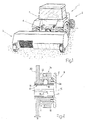
- number 1 indicates as a whole an agricultural machine comprising a drive unit 2 and an operating unit 3 associated with unit 2.
- Unit 2 has a power take-off 4 having a powered output shaft 5, which has a substantially horizontal longitudinal axis 6 and is mounted to rotate about axis 6 with respect to a frame 7 of unit 2 and under the control of a known actuating device not shown.
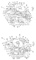
- unit 3 has an input shaft 8 comprising a tubular end portion 9, which has a longitudinal axis 10, is bounded internally by a surface 11 ( Figure 4) substantially coaxial with axis 10, and is movable, as described in detail later on, between an engaged position ( Figure 3), in which portion 9 is connected in angularly and axially fixed manner to shaft 5 and is rotated by shaft 5 about axis 6, and a release position ( Figure 2).
- portion 9 is connected in angularly fixed manner to shaft 5 by a splined coupling 12 comprising a number of teeth 13 (Figure 2) projecting outwards from an outer surface of shaft 5 and equally spaced about axis 6; and a number of grooves 14 ( Figure 4), which are equal in number to teeth 13, are formed on surface 11, are equally spaced about axis 10, and are so shaped and located as to each receive a relative tooth 13 when shaft 5 is inserted axially inside portion 9.
- a splined coupling 12 comprising a number of teeth 13 (Figure 2) projecting outwards from an outer surface of shaft 5 and equally spaced about axis 6; and a number of grooves 14 ( Figure 4), which are equal in number to teeth 13, are formed on surface 11, are equally spaced about axis 10, and are so shaped and located as to each receive a relative tooth 13 when shaft 5 is inserted axially inside portion 9.
- portion 9 is also connected in axially fixed manner to shaft 5 by a lock device 15 comprising a number of (in the example shown, three) lock balls 16 equally spaced about axis 10 and each housed inside a relative radial seat 17, which is formed through portion 9 at a relative groove 14, and is so shaped as to allow relative ball 16 to move crosswise to axis 10 when shaft 5 and portion 9 are moved, as described in detail later on, in a direction 18, parallel to axis 6, between said engaged and release positions.
- a lock device 15 comprising a number of (in the example shown, three) lock balls 16 equally spaced about axis 10 and each housed inside a relative radial seat 17, which is formed through portion 9 at a relative groove 14, and is so shaped as to allow relative ball 16 to move crosswise to axis 10 when shaft 5 and portion 9 are moved, as described in detail later on, in a direction 18, parallel to axis 6, between said engaged and release positions.
- Device 15 also comprises a sleeve 19, which is fitted to portion 9 coaxially with axis 10 and so as to slide, parallel to axis 10, between two annular flanges 20, 21 projecting radially outwards from the outer surface of portion 9.
- sleeve 19 is normally set, by a spring 22 interposed between flange 20 and sleeve 19, to a lock position ( Figure 4), wherein sleeve 19 contacts flange 21, and balls 16, moving crosswise to axis 10, engage respective seats 23 formed on teeth 13, are spaced apart by a distance approximately equal to but no greater than the diameter of shaft 5, and so enable portion 9 to grip shaft 5.
- shafts 5 and 8 are moved between the engaged and release positions by a hitch assembly 25 comprising an annular supporting plate 26 extending about shaft 5 and fixed releasably to frame 7 of drive unit 2; and a supporting unit 27 supporting portion 9.
- Unit 27 comprises a slide 28 fitted in sliding manner to plate 26, via the interposition of a crank mechanism 29, to move linearly in direction 18, and with respect to plate 26, between a forward position ( Figure 2) and a withdrawn position ( Figure 3).
- Crank mechanism 29 comprises two pairs of cranks 30 located on opposite sides of axis 6 in a horizontal direction 31 crosswise to direction 18.
- the cranks 30 in each pair of cranks 30 are hinged to each other at respective intermediate points to oscillate with respect to each other about a hinge axis 32 parallel to direction 31, and each extend between two respective axes 33, 34 parallel to axis 32, and of which axis 33 is the axis about which crank 30 rotates with respect to plate 26, and axis 34 is the axis about which crank 30 rotates with respect to slide 28.
- cranks 30 are rotated about relative axes 33 by an actuating device 35 comprising an actuating cylinder 36, which is hinged to a supporting bracket 37, projecting from plate 26 in direction 18, to oscillate, with respect to plate 26, about a hinge axis 38 substantially parallel to a vertical direction 39 perpendicular to directions 18 and 31.
- Cylinder 36 has an output rod (not shown) hinged to a first arm (not shown) of a rocker arm 40, which is hinged to a supporting bracket 41, projecting from plate 26 in direction 18, to oscillate, with respect to plate 26, about an axis 42 parallel to axis 38, and has a second arm (not shown) hinged to slide 28.
- Slide 28 is fitted removably with two guides 43 located on opposite sides of axis 6 in direction 31, extending parallel to direction 31, and each supporting a respective slide 44, which is substantially parallelepiped-shaped with a substantially rectangular cross section, and is connected in known manner to relative guide 43 to slide linearly in direction 31 along relative guide 43 and under the control of an actuating device 45 common to both slides 44.
- Device 45 comprises an actuating cylinder 46, which is fixed to one of slides 44, extends in direction 31, and has an output rod 47 fixed to the other slide 44.
- each slide 44 supports an arm 48 extending in direction 39 and comprising a substantially straight first portion 48a parallel to direction 39, and a curved, upwardly concave second portion 48b located beneath portion 48a.
- the two arms 48 are movable, with respect to each other in direction 31 and under the control of device 45, between a rest position, in which the two arms 48 are spaced apart by a distance greater than the diameter of portion 9, and a work position, in which the two arms 48 are spaced apart by a distance substantially equal to the diameter of portion 9 to define a guide 49, which is substantially fork-shaped, extends in a vertical plane perpendicular to axis 6, and is engaged in sliding manner by portion 9.
- hitch assembly 25 Operation of hitch assembly 25 will now be described as of the instant in which slide 28 is in the forward position, arms 48 are in the work position, and sleeve 19 is in the lock position.
- portion 9 is first inserted inside guide 49, is then moved along guide 49 in direction 39, and is finally locked in direction 39 coaxially with axis 6, i.e. in the release position, by means of a known ratchet device not shown.
- guide 49 moves sleeve 19, in opposition to spring 22, from the lock position to the release position, so that balls 16 are spaced apart by a distance approximately equal to but no less than the diameter of shaft 5.
- actuating cylinder 36 is operated to move slide 28 into the withdrawn position, so that portion 9 engages shaft 5, and teeth 13 engage relative grooves 14 to lock shaft 5 and portion 9 angularly to each other.
- actuating cylinder 46 is operated to move arms 48 into the rest position, so that arms 48 release both portion 9 and sleeve 19, sleeve 19 is thus moved by spring 22 into the lock position, and balls 16 engage relative seats 23 to lock shaft 5 and portion 9 axially to each other.
- shaft 5 of power take-off 4 is activated, and rotation of shaft 5 about axis 6 is transmitted to portion 9, which, being supported directly and solely by shaft 5, requires no rolling bearing.
Landscapes
- Life Sciences & Earth Sciences (AREA)
- Engineering & Computer Science (AREA)
- Mechanical Engineering (AREA)
- Soil Sciences (AREA)
- Environmental Sciences (AREA)
- Agricultural Machines (AREA)
- Transplanting Machines (AREA)
- Sowing (AREA)
- Catching Or Destruction (AREA)
- Soil Working Implements (AREA)
Abstract
Description
Claims (12)
- A hitch assembly for an agricultural machine comprising a drive unit (2) having at least one power take-off (4) having an output shaft (5) rotating about a first axis (6); an operating unit (2) having an input shaft (8) rotating about a second axis (10); and a splined coupling (12) for angularly locking said input shaft and said output shaft (8, 5); the hitch assembly comprising a supporting member (49) substantially in the form of a fork and comprising two arms (48) facing each other, the input shaft (8), in use, engaging the arms (48) in sliding manner to translate, in a first direction (39) substantially crosswise to said first axis (6), to and from a release position, wherein the input shaft (8) is coaxial with the output shaft (5); and first actuating means (29, 36) for moving the supporting member (49), in a second direction (18) substantially parallel to said first axis (6), to and from an engaged position, wherein the input shaft and the output shaft (8, 5) are locked angularly to each other by said splined coupling (12); and being characterized by also comprising second actuating means (45) for moving the arms (48), with respect to each other and in a third direction (31) substantially perpendicular to said first and said second direction (39, 18), to and from a rest position, wherein the arms (48), in use, release the input shaft (8).
- A hitch assembly as claimed in Claim 1, wherein the arms (48) are movable, with respect to each other and in said third direction (31), between said rest position and a work position, wherein the arms (48) are engaged in sliding manner by the input shaft (8); first locking means being provided to lock the input shaft (8) to the supporting member (49) in said first direction (39) when the input shaft (8) is in said release position.
- A hitch assembly as claimed in Claim 1 or 2, wherein said first actuating means (29, 36) comprise a crank mechanism (29), and an actuating cylinder (36) for operating the crank mechanism (29); the arms (48) being carried by said crank mechanism (29).
- A hitch assembly as claimed in any one of the foregoing Claims, wherein each arm (48) comprises a substantially straight first portion (48a) parallel to said first direction (39); and a curved second portion (48b) with its concavity facing upwards.
- A hitch assembly as claimed in any one of the foregoing Claims, wherein said second actuating means (45) comprise an actuating cylinder (46) extending in said third direction (31), fixed to one of the arms (48), and having an output rod (47) fixed to the other arm (48).
- An agricultural machine comprising a drive unit (2) having at least one power take-off (4) having an output shaft (5) rotating about a first axis (6); an operating unit (2) having an input shaft (8) rotating about a second axis (10); a splined coupling (12) for angularly locking said input shaft and said output shaft (8, 5); and a hitch assembly (25) as claimed in any one of Claims 1 to 5.
- An agricultural machine as claimed in Claim 6, and also comprising second locking means (20, 21) for locking the input shaft (8) to the supporting member (49) in said second direction (18) when the input shaft (8) is in said release position.
- An agricultural machine as claimed in Claim 7, wherein the second locking means (20, 21) comprise two annular flanges (20, 21) projecting radially outwards from said input shaft (8) and located on opposite sides of said supporting member (49) in said second direction (18) when the input shaft (8) is in said release position.
- An agricultural machine as claimed in any one of Claims 6 to 8, and also comprising third locking means (15) for axially locking said input shaft and said output shaft (8, 5) when the input shaft and the output shaft are in said engaged position.
- An agricultural machine as claimed in Claim 9, wherein the third locking means (15) comprise gripping means (16) for axially locking said input shaft and said output shaft (8, 5); and third actuating means (49, 22) for moving the gripping means (16) between a lock position locking the input shaft (8) to the output shaft (5), and a further release position.
- An agricultural machine as claimed in Claim 10, wherein the third actuating means (49, 22) comprise first push means (49) for moving the gripping means (16) from said lock position to said further release position; and second push means (22) for moving the gripping means (16) from said further release position to said lock position.
- An agricultural machine as claimed in Claim 11, wherein the first push means (49) are carried by the supporting member (49) to move the gripping means (16) from said lock position to said further release position as the input shaft (8) moves into said release position.
Applications Claiming Priority (2)
| Application Number | Priority Date | Filing Date | Title |
|---|---|---|---|
| IT000069A ITBO20040069A1 (en) | 2004-02-13 | 2004-02-13 | HOOKING GROUP FOR AN AGRICULTURAL MACHINE |
| ITBO20040069 | 2004-02-13 |
Publications (2)
| Publication Number | Publication Date |
|---|---|
| EP1563723A1 true EP1563723A1 (en) | 2005-08-17 |
| EP1563723B1 EP1563723B1 (en) | 2009-09-30 |
Family
ID=34685601
Family Applications (1)
| Application Number | Title | Priority Date | Filing Date |
|---|---|---|---|
| EP05101063A Expired - Lifetime EP1563723B1 (en) | 2004-02-13 | 2005-02-14 | Hitch assembly for an agricultural machine |
Country Status (5)
| Country | Link |
|---|---|
| EP (1) | EP1563723B1 (en) |
| AT (1) | ATE443984T1 (en) |
| DE (1) | DE602005016852D1 (en) |
| ES (1) | ES2353186T3 (en) |
| IT (1) | ITBO20040069A1 (en) |
Cited By (1)
| Publication number | Priority date | Publication date | Assignee | Title |
|---|---|---|---|---|
| EP2036421A1 (en) | 2007-09-11 | 2009-03-18 | GKN Walterscheid GmbH | Device for coupling a jointed shaft with a p.t.o. shaft of a tractor |
Citations (7)
| Publication number | Priority date | Publication date | Assignee | Title |
|---|---|---|---|---|
| DE3140917A1 (en) * | 1981-10-15 | 1983-06-16 | Armin 7995 Neukirch Waggershauser | Coupling device for accessory units of farm tractors |
| DE3612322A1 (en) * | 1986-04-11 | 1987-10-15 | Kloeckner Humboldt Deutz Ag | Quick-action coupling for the connection of agricultural working machines |
| DE3613708A1 (en) * | 1986-04-11 | 1987-12-17 | Kloeckner Humboldt Deutz Ag | Quick-action coupling for the connection of agricultural working machines |
| EP0568854A2 (en) * | 1992-04-21 | 1993-11-10 | Friedrich Mörtl Schleppergerätebau GmbH & Co. KG | Method and hitch for quickly mechanically connecting a tractor to an agricultural implement |
| DE4242995A1 (en) * | 1992-12-18 | 1994-06-23 | Walterscheid Gmbh Gkn | Coupling for connecting tractors to appliance |
| EP0617882A1 (en) * | 1993-04-01 | 1994-10-05 | Rupert Aigner | Device for connecting wheelable argicultural implements to tractors |
| EP1252807A1 (en) * | 2001-04-27 | 2002-10-30 | Bruno Bartolini | Hitch assembly for an agricultural machine |
-
2004
- 2004-02-13 IT IT000069A patent/ITBO20040069A1/en unknown
-
2005
- 2005-02-14 DE DE602005016852T patent/DE602005016852D1/en not_active Expired - Lifetime
- 2005-02-14 EP EP05101063A patent/EP1563723B1/en not_active Expired - Lifetime
- 2005-02-14 AT AT05101063T patent/ATE443984T1/en active
- 2005-02-14 ES ES05101063T patent/ES2353186T3/en not_active Expired - Lifetime
Patent Citations (7)
| Publication number | Priority date | Publication date | Assignee | Title |
|---|---|---|---|---|
| DE3140917A1 (en) * | 1981-10-15 | 1983-06-16 | Armin 7995 Neukirch Waggershauser | Coupling device for accessory units of farm tractors |
| DE3612322A1 (en) * | 1986-04-11 | 1987-10-15 | Kloeckner Humboldt Deutz Ag | Quick-action coupling for the connection of agricultural working machines |
| DE3613708A1 (en) * | 1986-04-11 | 1987-12-17 | Kloeckner Humboldt Deutz Ag | Quick-action coupling for the connection of agricultural working machines |
| EP0568854A2 (en) * | 1992-04-21 | 1993-11-10 | Friedrich Mörtl Schleppergerätebau GmbH & Co. KG | Method and hitch for quickly mechanically connecting a tractor to an agricultural implement |
| DE4242995A1 (en) * | 1992-12-18 | 1994-06-23 | Walterscheid Gmbh Gkn | Coupling for connecting tractors to appliance |
| EP0617882A1 (en) * | 1993-04-01 | 1994-10-05 | Rupert Aigner | Device for connecting wheelable argicultural implements to tractors |
| EP1252807A1 (en) * | 2001-04-27 | 2002-10-30 | Bruno Bartolini | Hitch assembly for an agricultural machine |
Cited By (4)
| Publication number | Priority date | Publication date | Assignee | Title |
|---|---|---|---|---|
| EP2036421A1 (en) | 2007-09-11 | 2009-03-18 | GKN Walterscheid GmbH | Device for coupling a jointed shaft with a p.t.o. shaft of a tractor |
| DE102007043032A1 (en) | 2007-09-11 | 2009-04-09 | Gkn Walterscheid Gmbh | Device for coupling a propeller shaft with a PTO shaft of a tractor |
| DE102007043032B4 (en) * | 2007-09-11 | 2009-07-02 | Gkn Walterscheid Gmbh | Device for coupling a propeller shaft with a PTO shaft of a tractor |
| US7997362B2 (en) | 2007-09-11 | 2011-08-16 | Gkn Walterscheid Gmbh | Device for coupling a universal joint shaft with a power take-off shaft of a tractor |
Also Published As
| Publication number | Publication date |
|---|---|
| EP1563723B1 (en) | 2009-09-30 |
| ATE443984T1 (en) | 2009-10-15 |
| ES2353186T3 (en) | 2011-02-28 |
| ITBO20040069A1 (en) | 2004-05-13 |
| DE602005016852D1 (en) | 2009-11-12 |
Similar Documents
| Publication | Publication Date | Title |
|---|---|---|
| JP6559664B2 (en) | Turret for tool machine | |
| JP5487902B2 (en) | Clutch actuator | |
| US10143484B2 (en) | Medical instrument | |
| CN105813889B (en) | Actuating device for vehicle seat and vehicle seat | |
| CN103538036B (en) | Switch element | |
| CN106388354A (en) | Electrically adjustable office chair | |
| US20170320538A1 (en) | Transmission | |
| US20130133471A1 (en) | Adjustable pedal assembly with swing arm | |
| CN110114263A (en) | Forecarriage with the rolling motor vehicles for rolling block piece | |
| CN101479134A (en) | Actuating element for a parking lock of a transmission and parking lock for a transmission | |
| US20110296934A1 (en) | Rotary drum for a gear control device for a motor-vehicle gearbox and a gear control device for a motor-vehicle gearbox having such a drum | |
| US4615592A (en) | Coupling for the drive of a mechanical stage | |
| EP1563723B1 (en) | Hitch assembly for an agricultural machine | |
| JP4890382B2 (en) | Management machine | |
| EP1595769A1 (en) | Self-propelled vehicle particularly for making turns with tight turning radii | |
| CN210914233U (en) | Rotating device compatible with multi-machine crankshaft | |
| EP1252807B1 (en) | Hitch assembly for an agricultural machine | |
| KR101411557B1 (en) | Device for latching and locking shift rockers of a shift device of a transmission | |
| EP3178723B1 (en) | Steering column for vehicles | |
| US1687721A (en) | Speed-changing mechanism | |
| US20170166238A1 (en) | Steering column for vehicles | |
| JPS5854295Y2 (en) | Steering clutch linkage state switching device for walking-type mobile agricultural machinery | |
| JP2013023172A (en) | Rotary device | |
| JPH0540896Y2 (en) | ||
| KR20140102338A (en) | Parking mechanism of automatic transmission |
Legal Events
| Date | Code | Title | Description |
|---|---|---|---|
| PUAI | Public reference made under article 153(3) epc to a published international application that has entered the european phase |
Free format text: ORIGINAL CODE: 0009012 |
|
| AK | Designated contracting states |
Kind code of ref document: A1 Designated state(s): AT BE BG CH CY CZ DE DK EE ES FI FR GB GR HU IE IS IT LI LT LU MC NL PL PT RO SE SI SK TR |
|
| AX | Request for extension of the european patent |
Extension state: AL BA HR LV MK YU |
|
| 17P | Request for examination filed |
Effective date: 20060216 |
|
| AKX | Designation fees paid |
Designated state(s): AT BE BG CH CY CZ DE DK EE ES FI FR GB GR HU IE IS IT LI LT LU MC NL PL PT RO SE SI SK TR |
|
| GRAP | Despatch of communication of intention to grant a patent |
Free format text: ORIGINAL CODE: EPIDOSNIGR1 |
|
| GRAS | Grant fee paid |
Free format text: ORIGINAL CODE: EPIDOSNIGR3 |
|
| GRAA | (expected) grant |
Free format text: ORIGINAL CODE: 0009210 |
|
| RAP1 | Party data changed (applicant data changed or rights of an application transferred) |
Owner name: ARIES S.R.L. |
|
| RAP1 | Party data changed (applicant data changed or rights of an application transferred) |
Owner name: ARIES S.R.L. |
|
| AK | Designated contracting states |
Kind code of ref document: B1 Designated state(s): AT BE BG CH CY CZ DE DK EE ES FI FR GB GR HU IE IS IT LI LT LU MC NL PL PT RO SE SI SK TR |
|
| REG | Reference to a national code |
Ref country code: CH Ref legal event code: EP Ref country code: GB Ref legal event code: FG4D |
|
| REG | Reference to a national code |
Ref country code: IE Ref legal event code: FG4D |
|
| REF | Corresponds to: |
Ref document number: 602005016852 Country of ref document: DE Date of ref document: 20091112 Kind code of ref document: P |
|
| PG25 | Lapsed in a contracting state [announced via postgrant information from national office to epo] |
Ref country code: SE Free format text: LAPSE BECAUSE OF FAILURE TO SUBMIT A TRANSLATION OF THE DESCRIPTION OR TO PAY THE FEE WITHIN THE PRESCRIBED TIME-LIMIT Effective date: 20090930 Ref country code: LT Free format text: LAPSE BECAUSE OF FAILURE TO SUBMIT A TRANSLATION OF THE DESCRIPTION OR TO PAY THE FEE WITHIN THE PRESCRIBED TIME-LIMIT Effective date: 20090930 |
|
| LTIE | Lt: invalidation of european patent or patent extension |
Effective date: 20090930 |
|
| PG25 | Lapsed in a contracting state [announced via postgrant information from national office to epo] |
Ref country code: SI Free format text: LAPSE BECAUSE OF FAILURE TO SUBMIT A TRANSLATION OF THE DESCRIPTION OR TO PAY THE FEE WITHIN THE PRESCRIBED TIME-LIMIT Effective date: 20090930 Ref country code: PL Free format text: LAPSE BECAUSE OF FAILURE TO SUBMIT A TRANSLATION OF THE DESCRIPTION OR TO PAY THE FEE WITHIN THE PRESCRIBED TIME-LIMIT Effective date: 20090930 |
|
| NLV1 | Nl: lapsed or annulled due to failure to fulfill the requirements of art. 29p and 29m of the patents act | ||
| PG25 | Lapsed in a contracting state [announced via postgrant information from national office to epo] |
Ref country code: CZ Free format text: LAPSE BECAUSE OF FAILURE TO SUBMIT A TRANSLATION OF THE DESCRIPTION OR TO PAY THE FEE WITHIN THE PRESCRIBED TIME-LIMIT Effective date: 20090930 Ref country code: IS Free format text: LAPSE BECAUSE OF FAILURE TO SUBMIT A TRANSLATION OF THE DESCRIPTION OR TO PAY THE FEE WITHIN THE PRESCRIBED TIME-LIMIT Effective date: 20100130 Ref country code: EE Free format text: LAPSE BECAUSE OF FAILURE TO SUBMIT A TRANSLATION OF THE DESCRIPTION OR TO PAY THE FEE WITHIN THE PRESCRIBED TIME-LIMIT Effective date: 20090930 Ref country code: RO Free format text: LAPSE BECAUSE OF FAILURE TO SUBMIT A TRANSLATION OF THE DESCRIPTION OR TO PAY THE FEE WITHIN THE PRESCRIBED TIME-LIMIT Effective date: 20090930 Ref country code: PT Free format text: LAPSE BECAUSE OF FAILURE TO SUBMIT A TRANSLATION OF THE DESCRIPTION OR TO PAY THE FEE WITHIN THE PRESCRIBED TIME-LIMIT Effective date: 20100201 |
|
| PG25 | Lapsed in a contracting state [announced via postgrant information from national office to epo] |
Ref country code: CY Free format text: LAPSE BECAUSE OF FAILURE TO SUBMIT A TRANSLATION OF THE DESCRIPTION OR TO PAY THE FEE WITHIN THE PRESCRIBED TIME-LIMIT Effective date: 20090930 Ref country code: SK Free format text: LAPSE BECAUSE OF FAILURE TO SUBMIT A TRANSLATION OF THE DESCRIPTION OR TO PAY THE FEE WITHIN THE PRESCRIBED TIME-LIMIT Effective date: 20090930 |
|
| PG25 | Lapsed in a contracting state [announced via postgrant information from national office to epo] |
Ref country code: BE Free format text: LAPSE BECAUSE OF FAILURE TO SUBMIT A TRANSLATION OF THE DESCRIPTION OR TO PAY THE FEE WITHIN THE PRESCRIBED TIME-LIMIT Effective date: 20090930 |
|
| PG25 | Lapsed in a contracting state [announced via postgrant information from national office to epo] |
Ref country code: NL Free format text: LAPSE BECAUSE OF FAILURE TO SUBMIT A TRANSLATION OF THE DESCRIPTION OR TO PAY THE FEE WITHIN THE PRESCRIBED TIME-LIMIT Effective date: 20090930 Ref country code: DK Free format text: LAPSE BECAUSE OF FAILURE TO SUBMIT A TRANSLATION OF THE DESCRIPTION OR TO PAY THE FEE WITHIN THE PRESCRIBED TIME-LIMIT Effective date: 20090930 |
|
| PLBE | No opposition filed within time limit |
Free format text: ORIGINAL CODE: 0009261 |
|
| STAA | Information on the status of an ep patent application or granted ep patent |
Free format text: STATUS: NO OPPOSITION FILED WITHIN TIME LIMIT |
|
| 26N | No opposition filed |
Effective date: 20100701 |
|
| REG | Reference to a national code |
Ref country code: CH Ref legal event code: PL |
|
| PG25 | Lapsed in a contracting state [announced via postgrant information from national office to epo] |
Ref country code: MC Free format text: LAPSE BECAUSE OF NON-PAYMENT OF DUE FEES Effective date: 20100301 Ref country code: GR Free format text: LAPSE BECAUSE OF FAILURE TO SUBMIT A TRANSLATION OF THE DESCRIPTION OR TO PAY THE FEE WITHIN THE PRESCRIBED TIME-LIMIT Effective date: 20091231 Ref country code: CH Free format text: LAPSE BECAUSE OF NON-PAYMENT OF DUE FEES Effective date: 20100228 Ref country code: LI Free format text: LAPSE BECAUSE OF NON-PAYMENT OF DUE FEES Effective date: 20100228 |
|
| REG | Reference to a national code |
Ref country code: ES Ref legal event code: FG2A Effective date: 20110216 |
|
| PG25 | Lapsed in a contracting state [announced via postgrant information from national office to epo] |
Ref country code: IT Free format text: LAPSE BECAUSE OF NON-PAYMENT OF DUE FEES Effective date: 20100214 |
|
| PGRI | Patent reinstated in contracting state [announced from national office to epo] |
Ref country code: IT Effective date: 20110616 |
|
| PG25 | Lapsed in a contracting state [announced via postgrant information from national office to epo] |
Ref country code: BG Free format text: LAPSE BECAUSE OF FAILURE TO SUBMIT A TRANSLATION OF THE DESCRIPTION OR TO PAY THE FEE WITHIN THE PRESCRIBED TIME-LIMIT Effective date: 20090930 Ref country code: LU Free format text: LAPSE BECAUSE OF NON-PAYMENT OF DUE FEES Effective date: 20100214 Ref country code: HU Free format text: LAPSE BECAUSE OF FAILURE TO SUBMIT A TRANSLATION OF THE DESCRIPTION OR TO PAY THE FEE WITHIN THE PRESCRIBED TIME-LIMIT Effective date: 20100401 |
|
| PG25 | Lapsed in a contracting state [announced via postgrant information from national office to epo] |
Ref country code: TR Free format text: LAPSE BECAUSE OF FAILURE TO SUBMIT A TRANSLATION OF THE DESCRIPTION OR TO PAY THE FEE WITHIN THE PRESCRIBED TIME-LIMIT Effective date: 20090930 |
|
| REG | Reference to a national code |
Ref country code: FR Ref legal event code: PLFP Year of fee payment: 11 |
|
| PGFP | Annual fee paid to national office [announced via postgrant information from national office to epo] |
Ref country code: ES Payment date: 20150828 Year of fee payment: 11 Ref country code: FI Payment date: 20150820 Year of fee payment: 11 Ref country code: DE Payment date: 20150831 Year of fee payment: 11 Ref country code: IE Payment date: 20150821 Year of fee payment: 11 Ref country code: GB Payment date: 20150820 Year of fee payment: 11 |
|
| PGFP | Annual fee paid to national office [announced via postgrant information from national office to epo] |
Ref country code: FR Payment date: 20150828 Year of fee payment: 11 Ref country code: AT Payment date: 20150821 Year of fee payment: 11 |
|
| PGFP | Annual fee paid to national office [announced via postgrant information from national office to epo] |
Ref country code: IT Payment date: 20150819 Year of fee payment: 11 |
|
| REG | Reference to a national code |
Ref country code: DE Ref legal event code: R119 Ref document number: 602005016852 Country of ref document: DE |
|
| REG | Reference to a national code |
Ref country code: AT Ref legal event code: MM01 Ref document number: 443984 Country of ref document: AT Kind code of ref document: T Effective date: 20160214 |
|
| GBPC | Gb: european patent ceased through non-payment of renewal fee |
Effective date: 20160214 |
|
| PG25 | Lapsed in a contracting state [announced via postgrant information from national office to epo] |
Ref country code: FI Free format text: LAPSE BECAUSE OF NON-PAYMENT OF DUE FEES Effective date: 20160214 |
|
| REG | Reference to a national code |
Ref country code: FR Ref legal event code: ST Effective date: 20161028 |
|
| PG25 | Lapsed in a contracting state [announced via postgrant information from national office to epo] |
Ref country code: AT Free format text: LAPSE BECAUSE OF NON-PAYMENT OF DUE FEES Effective date: 20160214 |
|
| REG | Reference to a national code |
Ref country code: IE Ref legal event code: MM4A |
|
| PG25 | Lapsed in a contracting state [announced via postgrant information from national office to epo] |
Ref country code: IT Free format text: LAPSE BECAUSE OF NON-PAYMENT OF DUE FEES Effective date: 20160214 |
|
| PG25 | Lapsed in a contracting state [announced via postgrant information from national office to epo] |
Ref country code: IE Free format text: LAPSE BECAUSE OF NON-PAYMENT OF DUE FEES Effective date: 20160214 Ref country code: FR Free format text: LAPSE BECAUSE OF NON-PAYMENT OF DUE FEES Effective date: 20160229 Ref country code: GB Free format text: LAPSE BECAUSE OF NON-PAYMENT OF DUE FEES Effective date: 20160214 Ref country code: DE Free format text: LAPSE BECAUSE OF NON-PAYMENT OF DUE FEES Effective date: 20160901 |
|
| PG25 | Lapsed in a contracting state [announced via postgrant information from national office to epo] |
Ref country code: ES Free format text: LAPSE BECAUSE OF NON-PAYMENT OF DUE FEES Effective date: 20160215 |