EP1564033A1 - Kupplungskörper - Google Patents
Kupplungskörper Download PDFInfo
- Publication number
- EP1564033A1 EP1564033A1 EP04450234A EP04450234A EP1564033A1 EP 1564033 A1 EP1564033 A1 EP 1564033A1 EP 04450234 A EP04450234 A EP 04450234A EP 04450234 A EP04450234 A EP 04450234A EP 1564033 A1 EP1564033 A1 EP 1564033A1
- Authority
- EP
- European Patent Office
- Prior art keywords
- coupling
- coupling body
- lubrication
- lubricating
- ball
- Prior art date
- Legal status (The legal status is an assumption and is not a legal conclusion. Google has not performed a legal analysis and makes no representation as to the accuracy of the status listed.)
- Granted
Links
Images

Classifications
-
- B—PERFORMING OPERATIONS; TRANSPORTING
- B60—VEHICLES IN GENERAL
- B60D—VEHICLE CONNECTIONS
- B60D1/00—Traction couplings; Hitches; Draw-gear; Towing devices
- B60D1/01—Traction couplings or hitches characterised by their type
- B60D1/06—Ball-and-socket hitches
-
- B—PERFORMING OPERATIONS; TRANSPORTING
- B60—VEHICLES IN GENERAL
- B60D—VEHICLE CONNECTIONS
- B60D1/00—Traction couplings; Hitches; Draw-gear; Towing devices
- B60D1/58—Auxiliary devices
- B60D1/586—Lubrication means
Definitions
- the invention relates to a coupling body with a first contact surface for contact with a drawbar eye.
- Such coupling body can, depending on the design of the drawbar a different Have shape.
- a molding as a coupling ball of the known Coupling body a central lubrication hole and the drawbar eye grooves for distribution of Have lubricating fluid.
- the disadvantage here is that often a non-uniform Lubrication occurs.
- the object of the invention is to provide a coupling body of the type mentioned, in which the known disadvantages are avoided, the high reliability and
- This lubrication is included largely insensitive to contamination and / or wear and therefore poses the entire life of the coupling body reliable lubrication safely.
- the invention in a further development of the invention can be provided that it as a coupling ball with a is formed in the symmetry axis of the coupling ball lying first lubricating opening. This can be on the entire contact surface of the coupling ball good lubrication be achieved, whereby a local welding of the coupling ball with the drawbar eye can be prevented.
- a further embodiment of the invention can be provided that he as Saddle bush is formed.
- ring-shaped drawbar eye provided lubrication of the contact surface.
- the saddle bushing can do this be formed interchangeable, making for different loads easy and quickly a suitable saddle bushing can be provided.
- the at least one Lubrication device comprises at least one lubrication channel.
- the lubrication channel Through the lubrication channel can Lubricant coming from a central lubrication via the lubrication device be distributed, which in particular a permanent lubrication are easily provided can.
- a variant of the invention may consist in that the first lubricating opening and the Lubrication channel connected to a central lubrication line in a branching area are. This allows the lubrication opening and the lubrication channel with only one connection be operated on a central lubrication system.
- the Branching area substantially in the middle of the coupling body, in particular in the center of the coupling ball, is arranged. Due to the arrangement in the middle of the Coupling body can only a small weakening of the load-bearing cross sections through the Lubrication be achieved. In particular, in a coupling ball have through the ball center cross-sections on a particularly large area.
- the cross section the lubrication channel is smaller than the cross section of the first lubrication opening. It can Just make sure that the leaking through the lubrication channel Lubricant quantity smaller than that exiting through the first lubricating opening Lubricant amount is, thereby reducing the amount of lubricant supplied a good lubrication in the area of the lubrication opening is ensured.
- the at least one Lubrication device comprises a receiving device for a liner element.
- the Insertion element can be a discontinuous provision of the lubricant easy be realized.
- the material of the insert element comprises a lubricant, in particular graphite.
- a lubricant in particular graphite.
- This can be a Overheating of the contact surface are particularly sure to be prevented. Is it due to a lack of lubricant to overheat and abrasion of the Coupling body, so a part of the insert element is abraded, whereby the Lubricant passes between the drawbar eye and the coupling body and lubrication is restored.
- the insert element is oil-soaked.
- the lubricating effect of Insert element further improved.
- the invention further relates to a coupling.
- Another object of the invention is to provide a coupling in which the known Disadvantages are avoided and the high reliability and safety of the clutch ensures that is easy and inexpensive to produce, has a long life and ensures a reliable function over its lifetime.
- the coupling body a Coupling ball is and that the symmetry axis of the coupling ball - in the operating position of the Coupling seen - opposite the vertical in the direction of a towing vehicle to one Angle inclined, in particular inclined by about 20 °, is. Due to the inclined arrangement of Coupling ball, the lubrication opening both in support loads and at Tensile stress can be arranged in a highly loaded area. This allows the Number and the dimensions of the lubrication devices are kept particularly low and yet a good and reliable lubrication of the entire bearing area be ensured.
- the Coupling ball is pivotally mounted and in a plurality of positions with A different angle can be fixed. This allows the alignment of the Coupling ball can be easily adapted to different applications.
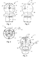
- Figs. 1 to 4 is a first embodiment of an inventive Coupling body 1 with a first contact surface 11 for contact with a drawbar eye shown.
- the coupling body 1 are more outside the axis of symmetry 12 of the Coupling body 1 lying and the contact surface 11 penetrating lubrication devices 2 provided.
- inventive coupling body 1 all parts of a coupling 9 can be formed be, which have a contact surface 11 for contact with a drawbar eye. It is the Towing eye in the operation of the clutch and in the engaged state with the contact surface 11th at least temporarily in contact.
- the symmetry axis 12 is usually substantially Also, an axis of symmetry of the contact surface 11.
- the coupling body can in particular as Coupling ball 19 or as a saddle bushing 18, as shown in FIGS. 5 to 8 Second embodiment of the coupling body according to the invention, be formed.
- the saddle bushing 18 can be used in particular in couplings with a substantially U-shaped Pulling jaw and a moving central pin are used, whereby they are in Region de central pin is arranged.
- first lubricating opening 3 When coupling balls 19, it is customary in the axis of symmetry 12 of the coupling ball 19th form lying first lubricating opening 3. Through the first lubrication opening can Lubricant can be introduced into the central region of the contact surface 11. By the Lubricant may be excessive heating of the contact surface 11 and a local Welding the drawbar eye with the coupling body in this area can be avoided.
- the coupling body 1 according to the invention is at least one outside the Symmetryeachse 12 of the coupling body 1 lying and the contact surface penetrating Lubrication device 2 is provided.
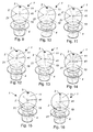
- Figs. 9 to 16 are different Embodiments of the coupling body 1 according to the invention shown, each one have different number lubrication 2.
- the lubricating devices 2 Depending on the expected load of the coupling at different points of the Contact surface 11 may be arranged.
- the coupling balls 19 according to FIGS. 9 to 14 are particularly suitable for substantially positive support loads, the coupling ball 19 of FIG. 15 for neutral support loads and high Pull-compressive stress in the direction of travel of the towing vehicle and the coupling ball as shown in FIG. 16 for negative support loads.
- the at least one comprises Lubrication device 2 at least one lubrication channel 21.
- the lubrication channel 21 and the first Lubrication port 3 are connected to a central lubrication line 4 in a branching area 41 connected.
- the lubrication line 4 can open into a lubricant reservoir and / or be provided for connection to a central lubrication system.
- the branching portion 41 may be located substantially at the center of the coupling body 1 be arranged. In particular, in the coupling ball 19 can thereby a high Resilience of the coupling ball 19 can be ensured.
- Coupling body 1 which is designed as a saddle bushing 18, includes the at least one Lubrication device 2 a receiving device 25 for an insert element 5. Furthermore the insert elements 5 are shown, wherein one of the insert elements 5 from the Receiving device 25 is removed.
- the material of the insert element 5 is a lubricant includes, in particular graphite appears suitable. This happens at one Wear of the coupling body 1 also to abrasion of the insert element 5, whereby Lubricant enters the area between the contact surface 11 and the drawbar, the Sliding properties of the drawbar eye on the contact surface 11 can be improved and another Wear is avoided. Furthermore, the insert element in the new state of Coupling body 1 protrude from this and in operation to the contour of the Contact surface 11 are removed, creating a particularly good lubrication of the new Coupling body 1 can be provided.
- the lubricating effect of the insert element 5 can be further improved if it oil-soaked. As a result, in particular with an increase in the temperature and / or the Pressure improved lubrication can be ensured.
- the at least one lubrication device 2 comprises Both lubrication channels 21 and receiving devices 25 for the insert element. 5
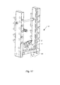
- a coupling 9 is shown with a coupling body 1 according to the invention.
- an angle ⁇ of about 20 ° appears to be suitable.
- the coupling ball 19 is pivotally mounted and in a plurality of positions with a different angle ⁇ can be fixed.
- a support element, the coupling ball 19 and a hold-down includes pivotally mounted in a guide.
- the angle ⁇ as a function be selected from the vertical load and traction, which can be ensured that the Lubrication opening 3 is arranged in operation in a region with particularly high voltages is.
- the receiving device 25 for the insert element 5 may also be arranged in the axis of symmetry 12.
Landscapes
- Engineering & Computer Science (AREA)
- Transportation (AREA)
- Mechanical Engineering (AREA)
- Pivots And Pivotal Connections (AREA)
Abstract
Description
Claims (13)
- Kupplungskörper (1) mit einer ersten Kontaktfläche (11) zum Kontakt mit einer Zugöse dadurch gekennzeichnet, dass wenigstens eine außerhalb der Symmetrieachse (12) des Kupplungskörpers (1) liegende und die Kontaktfläche (11) durchdringende Schmiereinrichtung (2) vorgesehen ist.
- Kupplungskörper (1) nach Anspruch 1, dadurch gekennzeichnet, dass er als Kupplungskugel (19) mit einer in der Symmetrieachse (12) der Kupplungskugel (19) liegenden ersten Schmieröffnung (3) ausgebildet ist
- Kupplungskörper (1) nach Anspruch 1, dadurch gekennzeichnet, dass er als Sattelbuchse (18) ausgebildet ist.
- Kupplungskörper (1) nach Anspruch 1, 2 oder 3, dadurch gekennzeichnet, dass die wenigstens eine Schmiereinrichtung (2) zumindest einen Schmierkanal (21) umfasst.
- Kupplungskörper (1) nach Anspruch 4, dadurch gekennzeichnet, dass die erste Schmieröffnung (3) und der Schmierkanal (21) mit einer zentralen Schmierleitung (4) in einem Verzweigungsbereich (41) verbunden sind.
- Kupplungskörper (1) nach Anspruch 5, dadurch gekennzeichnet, dass der Verzweigungsbereich (41) im Wesentlichen in der Mitte des Kupplungskörpers (1), insbesondere in der Mitte der Kupplungskugel (19), angeordnet ist.
- Kupplungskörper (1) nach einem der Ansprüche 4 bis 6, dadurch gekennzeichnet, dass der Querschnitt des Schmierkanals (21) kleiner als der Querschnitt der ersten Schmieröffnung (3) ist.
- Kupplungskörper (1) nach einem der Ansprüche 1 bis 7, dadurch gekennzeichnet, dass die wenigstens eine Schmiereinrichtung (2) eine Aufnahmevorrichtung (25) für ein Einlageelement (5) umfasst.
- Kupplungskörper (1) nach Anspruch 8, dadurch gekennzeichnet, dass das Material des Einlageelementes (5) einen Schmierstoff, insbesondere Graphit, umfasst.
- Kupplungskörper (1) nach Anspruch 8 oder 9, dadurch gekennzeichnet, dass das Einlageelement (5) ölgetränkt ist.
- Kupplung (9), dadurch gekennzeichnet dass ein Kupplungskörper (1) nach einem der Ansprüche 1 bis 10 vorgesehen ist.
- Kupplung (9) nach Anspruch 11, dadurch gekennzeichnet, dass der Kupplungskörper (1) eine Kupplungskugel (19) ist und dass die Symmetrieachse (12) der Kupplungskugel (19) - in Betriebslage der Kupplung (9) gesehen - gegenüber der Lotrechten in Richtung eines Zugfahrzeuges um einen Winkel (α) geneigt, insbesondere um etwa 20° geneigt, ist.
- Kupplung (9) nach Anspruch 12, dadurch gekennzeichnet, dass die Kupplungskugel (19) verschwenkbar angeordnet ist und in einer Mehrzahl an Stellungen mit einem unterschiedlichen Winkel (α) fixierbar ist.
Applications Claiming Priority (2)
| Application Number | Priority Date | Filing Date | Title |
|---|---|---|---|
| AT0023004A AT413361B (de) | 2004-02-13 | 2004-02-13 | Kupplungskörper |
| AT2302004 | 2004-02-13 |
Publications (2)
| Publication Number | Publication Date |
|---|---|
| EP1564033A1 true EP1564033A1 (de) | 2005-08-17 |
| EP1564033B1 EP1564033B1 (de) | 2007-09-05 |
Family
ID=34682561
Family Applications (1)
| Application Number | Title | Priority Date | Filing Date |
|---|---|---|---|
| EP04450234A Expired - Lifetime EP1564033B1 (de) | 2004-02-13 | 2004-12-17 | Kupplungskörper |
Country Status (3)
| Country | Link |
|---|---|
| EP (1) | EP1564033B1 (de) |
| AT (2) | AT413361B (de) |
| DE (1) | DE502004004870D1 (de) |
Cited By (2)
| Publication number | Priority date | Publication date | Assignee | Title |
|---|---|---|---|---|
| EP2682290A1 (de) * | 2012-07-04 | 2014-01-08 | RockingerAgriculture GmbH | Kupplungspfanne mit Festkörperschmierstoff |
| EP3666558A1 (de) * | 2018-12-13 | 2020-06-17 | Pfanzelt Maschinenbau GmbH | Anhängerkupplung |
Citations (3)
| Publication number | Priority date | Publication date | Assignee | Title |
|---|---|---|---|---|
| US2884261A (en) * | 1957-10-11 | 1959-04-28 | Elmer M Farr | Trailer hitch |
| US4832360A (en) * | 1988-03-17 | 1989-05-23 | Christian Douglas R | Greaseball hitch |
| US5205574A (en) * | 1991-08-05 | 1993-04-27 | Heath John A | Tow hitch apparatus |
-
2004
- 2004-02-13 AT AT0023004A patent/AT413361B/de not_active IP Right Cessation
- 2004-12-17 EP EP04450234A patent/EP1564033B1/de not_active Expired - Lifetime
- 2004-12-17 AT AT04450234T patent/ATE372220T1/de not_active IP Right Cessation
- 2004-12-17 DE DE502004004870T patent/DE502004004870D1/de not_active Expired - Lifetime
Patent Citations (3)
| Publication number | Priority date | Publication date | Assignee | Title |
|---|---|---|---|---|
| US2884261A (en) * | 1957-10-11 | 1959-04-28 | Elmer M Farr | Trailer hitch |
| US4832360A (en) * | 1988-03-17 | 1989-05-23 | Christian Douglas R | Greaseball hitch |
| US5205574A (en) * | 1991-08-05 | 1993-04-27 | Heath John A | Tow hitch apparatus |
Cited By (3)
| Publication number | Priority date | Publication date | Assignee | Title |
|---|---|---|---|---|
| EP2682290A1 (de) * | 2012-07-04 | 2014-01-08 | RockingerAgriculture GmbH | Kupplungspfanne mit Festkörperschmierstoff |
| DE102012211666B4 (de) * | 2012-07-04 | 2024-12-24 | Rockinger Agriculture Gmbh | Kupplungspfanne mit Festkörperschmierstoff |
| EP3666558A1 (de) * | 2018-12-13 | 2020-06-17 | Pfanzelt Maschinenbau GmbH | Anhängerkupplung |
Also Published As
| Publication number | Publication date |
|---|---|
| ATA2302004A (de) | 2005-07-15 |
| EP1564033B1 (de) | 2007-09-05 |
| ATE372220T1 (de) | 2007-09-15 |
| AT413361B (de) | 2006-02-15 |
| DE502004004870D1 (de) | 2007-10-18 |
Similar Documents
| Publication | Publication Date | Title |
|---|---|---|
| DE2804808C3 (de) | Bremsbackenhalterung für eine Teilbelagscheibenbremse, insbesondere für Kraftfahrzeuge | |
| DE2210466C3 (de) | Scharniergelenk einer Gleiskette | |
| DE102018202706B4 (de) | Führungsschuh | |
| DE69905508T2 (de) | Geschwindigkeitserhöhende Stau-Förderkette | |
| AT504906A4 (de) | Niederhaltervorrichtung | |
| DE102017213148B4 (de) | Gleitringdichtungsanordnung eines hydrodynamischen Retarders sowie hydrodynamischer Retarder | |
| DE3036141C2 (de) | Anschlußverbindungsstück zum Anschließen von aus elastischem oder gummiähnlichem Material bestehenden Leitungen | |
| DE102019206594B4 (de) | Lagerkäfig für ein Wälzlager | |
| WO2019076655A1 (de) | Aufzugsanlage mit umlenkelementen mit verschiedenen rillengeometrien | |
| DE60002522T2 (de) | Kupplungsvorrichtung | |
| DE102004039641B4 (de) | Längsverschiebeeinheit mit Käfigsicherung | |
| EP1564033B1 (de) | Kupplungskörper | |
| DE112014003608B4 (de) | Schnellverbinder | |
| DE19926248B4 (de) | Gleitschuh eines Schaltelementes einer Schalteinrichtung | |
| DE102010051268B4 (de) | Kugelgewindetrieb vom Typ ohne trennende Zwischenstücke zwischen den Kugeln für eine elektromechanische Fahrzeuglenkung | |
| DE202022103458U1 (de) | Energieführungskette mit Zugseil-Detektoranordnung | |
| EP1488942A1 (de) | Kupplungsvorrichtung | |
| DE60032065T2 (de) | Kettenlänge für Gleiskette | |
| DE68903782T2 (de) | Kupplungen. | |
| DE112008000851B4 (de) | Dichtteil für eine Wälzvorrichtung und Wälzvorrichtung | |
| DE102023104695A1 (de) | Kupplungsanordnung für einen landwirtschaftlichen Traktor | |
| DE10340672B4 (de) | Linearführung | |
| DE102008031825A1 (de) | Niederhalter | |
| DE3242946C2 (de) | Längenveränderliche Kreuzgelenkwelle | |
| DE202017107083U1 (de) | Riemenantrieb |
Legal Events
| Date | Code | Title | Description |
|---|---|---|---|
| PUAI | Public reference made under article 153(3) epc to a published international application that has entered the european phase |
Free format text: ORIGINAL CODE: 0009012 |
|
| AK | Designated contracting states |
Kind code of ref document: A1 Designated state(s): AT BE BG CH CY CZ DE DK EE ES FI FR GB GR HU IE IS IT LI LT LU MC NL PL PT RO SE SI SK TR |
|
| AX | Request for extension of the european patent |
Extension state: AL BA HR LV MK YU |
|
| 17P | Request for examination filed |
Effective date: 20060217 |
|
| AKX | Designation fees paid |
Designated state(s): AT BE BG CH CY CZ DE DK EE ES FI FR GB GR HU IE IS IT LI LT LU MC NL PL PT RO SE SI SK TR |
|
| 17Q | First examination report despatched |
Effective date: 20060726 |
|
| GRAP | Despatch of communication of intention to grant a patent |
Free format text: ORIGINAL CODE: EPIDOSNIGR1 |
|
| GRAS | Grant fee paid |
Free format text: ORIGINAL CODE: EPIDOSNIGR3 |
|
| GRAA | (expected) grant |
Free format text: ORIGINAL CODE: 0009210 |
|
| AK | Designated contracting states |
Kind code of ref document: B1 Designated state(s): AT BE BG CH CY CZ DE DK EE ES FI FR GB GR HU IE IS IT LI LT LU MC NL PL PT RO SE SI SK TR |
|
| REG | Reference to a national code |
Ref country code: GB Ref legal event code: FG4D Free format text: NOT ENGLISH |
|
| REG | Reference to a national code |
Ref country code: CH Ref legal event code: EP |
|
| REF | Corresponds to: |
Ref document number: 502004004870 Country of ref document: DE Date of ref document: 20071018 Kind code of ref document: P |
|
| REG | Reference to a national code |
Ref country code: IE Ref legal event code: FG4D Free format text: LANGUAGE OF EP DOCUMENT: GERMAN |
|
| PG25 | Lapsed in a contracting state [announced via postgrant information from national office to epo] |
Ref country code: ES Free format text: LAPSE BECAUSE OF FAILURE TO SUBMIT A TRANSLATION OF THE DESCRIPTION OR TO PAY THE FEE WITHIN THE PRESCRIBED TIME-LIMIT Effective date: 20071216 Ref country code: FI Free format text: LAPSE BECAUSE OF FAILURE TO SUBMIT A TRANSLATION OF THE DESCRIPTION OR TO PAY THE FEE WITHIN THE PRESCRIBED TIME-LIMIT Effective date: 20070905 Ref country code: LT Free format text: LAPSE BECAUSE OF FAILURE TO SUBMIT A TRANSLATION OF THE DESCRIPTION OR TO PAY THE FEE WITHIN THE PRESCRIBED TIME-LIMIT Effective date: 20070905 |
|
| PG25 | Lapsed in a contracting state [announced via postgrant information from national office to epo] |
Ref country code: PL Free format text: LAPSE BECAUSE OF FAILURE TO SUBMIT A TRANSLATION OF THE DESCRIPTION OR TO PAY THE FEE WITHIN THE PRESCRIBED TIME-LIMIT Effective date: 20070905 |
|
| NLV1 | Nl: lapsed or annulled due to failure to fulfill the requirements of art. 29p and 29m of the patents act | ||
| GBV | Gb: ep patent (uk) treated as always having been void in accordance with gb section 77(7)/1977 [no translation filed] | ||
| REG | Reference to a national code |
Ref country code: IE Ref legal event code: FD4D |
|
| PG25 | Lapsed in a contracting state [announced via postgrant information from national office to epo] |
Ref country code: GR Free format text: LAPSE BECAUSE OF FAILURE TO SUBMIT A TRANSLATION OF THE DESCRIPTION OR TO PAY THE FEE WITHIN THE PRESCRIBED TIME-LIMIT Effective date: 20071206 Ref country code: NL Free format text: LAPSE BECAUSE OF FAILURE TO SUBMIT A TRANSLATION OF THE DESCRIPTION OR TO PAY THE FEE WITHIN THE PRESCRIBED TIME-LIMIT Effective date: 20070905 |
|
| EN | Fr: translation not filed | ||
| PG25 | Lapsed in a contracting state [announced via postgrant information from national office to epo] |
Ref country code: IE Free format text: LAPSE BECAUSE OF FAILURE TO SUBMIT A TRANSLATION OF THE DESCRIPTION OR TO PAY THE FEE WITHIN THE PRESCRIBED TIME-LIMIT Effective date: 20070905 Ref country code: IS Free format text: LAPSE BECAUSE OF FAILURE TO SUBMIT A TRANSLATION OF THE DESCRIPTION OR TO PAY THE FEE WITHIN THE PRESCRIBED TIME-LIMIT Effective date: 20080105 Ref country code: CZ Free format text: LAPSE BECAUSE OF FAILURE TO SUBMIT A TRANSLATION OF THE DESCRIPTION OR TO PAY THE FEE WITHIN THE PRESCRIBED TIME-LIMIT Effective date: 20070905 Ref country code: GB Free format text: LAPSE BECAUSE OF FAILURE TO SUBMIT A TRANSLATION OF THE DESCRIPTION OR TO PAY THE FEE WITHIN THE PRESCRIBED TIME-LIMIT Effective date: 20070905 Ref country code: SK Free format text: LAPSE BECAUSE OF FAILURE TO SUBMIT A TRANSLATION OF THE DESCRIPTION OR TO PAY THE FEE WITHIN THE PRESCRIBED TIME-LIMIT Effective date: 20070905 Ref country code: PT Free format text: LAPSE BECAUSE OF FAILURE TO SUBMIT A TRANSLATION OF THE DESCRIPTION OR TO PAY THE FEE WITHIN THE PRESCRIBED TIME-LIMIT Effective date: 20080206 |
|
| BERE | Be: lapsed |
Owner name: SCHARMULLER, JOSEF Effective date: 20071231 |
|
| PG25 | Lapsed in a contracting state [announced via postgrant information from national office to epo] |
Ref country code: SE Free format text: LAPSE BECAUSE OF FAILURE TO SUBMIT A TRANSLATION OF THE DESCRIPTION OR TO PAY THE FEE WITHIN THE PRESCRIBED TIME-LIMIT Effective date: 20071205 Ref country code: RO Free format text: LAPSE BECAUSE OF FAILURE TO SUBMIT A TRANSLATION OF THE DESCRIPTION OR TO PAY THE FEE WITHIN THE PRESCRIBED TIME-LIMIT Effective date: 20070905 |
|
| PLBE | No opposition filed within time limit |
Free format text: ORIGINAL CODE: 0009261 |
|
| STAA | Information on the status of an ep patent application or granted ep patent |
Free format text: STATUS: NO OPPOSITION FILED WITHIN TIME LIMIT |
|
| PG25 | Lapsed in a contracting state [announced via postgrant information from national office to epo] |
Ref country code: DK Free format text: LAPSE BECAUSE OF FAILURE TO SUBMIT A TRANSLATION OF THE DESCRIPTION OR TO PAY THE FEE WITHIN THE PRESCRIBED TIME-LIMIT Effective date: 20070905 Ref country code: MC Free format text: LAPSE BECAUSE OF NON-PAYMENT OF DUE FEES Effective date: 20071231 |
|
| 26N | No opposition filed |
Effective date: 20080606 |
|
| PG25 | Lapsed in a contracting state [announced via postgrant information from national office to epo] |
Ref country code: FR Free format text: LAPSE BECAUSE OF FAILURE TO SUBMIT A TRANSLATION OF THE DESCRIPTION OR TO PAY THE FEE WITHIN THE PRESCRIBED TIME-LIMIT Effective date: 20080502 Ref country code: BE Free format text: LAPSE BECAUSE OF NON-PAYMENT OF DUE FEES Effective date: 20071231 |
|
| PG25 | Lapsed in a contracting state [announced via postgrant information from national office to epo] |
Ref country code: EE Free format text: LAPSE BECAUSE OF FAILURE TO SUBMIT A TRANSLATION OF THE DESCRIPTION OR TO PAY THE FEE WITHIN THE PRESCRIBED TIME-LIMIT Effective date: 20070905 |
|
| PG25 | Lapsed in a contracting state [announced via postgrant information from national office to epo] |
Ref country code: AT Free format text: LAPSE BECAUSE OF NON-PAYMENT OF DUE FEES Effective date: 20071217 |
|
| PG25 | Lapsed in a contracting state [announced via postgrant information from national office to epo] |
Ref country code: SI Free format text: LAPSE BECAUSE OF FAILURE TO SUBMIT A TRANSLATION OF THE DESCRIPTION OR TO PAY THE FEE WITHIN THE PRESCRIBED TIME-LIMIT Effective date: 20070905 |
|
| PG25 | Lapsed in a contracting state [announced via postgrant information from national office to epo] |
Ref country code: CY Free format text: LAPSE BECAUSE OF FAILURE TO SUBMIT A TRANSLATION OF THE DESCRIPTION OR TO PAY THE FEE WITHIN THE PRESCRIBED TIME-LIMIT Effective date: 20070905 |
|
| REG | Reference to a national code |
Ref country code: CH Ref legal event code: PL |
|
| PG25 | Lapsed in a contracting state [announced via postgrant information from national office to epo] |
Ref country code: LU Free format text: LAPSE BECAUSE OF NON-PAYMENT OF DUE FEES Effective date: 20071217 Ref country code: BG Free format text: LAPSE BECAUSE OF FAILURE TO SUBMIT A TRANSLATION OF THE DESCRIPTION OR TO PAY THE FEE WITHIN THE PRESCRIBED TIME-LIMIT Effective date: 20071205 |
|
| PG25 | Lapsed in a contracting state [announced via postgrant information from national office to epo] |
Ref country code: HU Free format text: LAPSE BECAUSE OF FAILURE TO SUBMIT A TRANSLATION OF THE DESCRIPTION OR TO PAY THE FEE WITHIN THE PRESCRIBED TIME-LIMIT Effective date: 20080306 Ref country code: TR Free format text: LAPSE BECAUSE OF FAILURE TO SUBMIT A TRANSLATION OF THE DESCRIPTION OR TO PAY THE FEE WITHIN THE PRESCRIBED TIME-LIMIT Effective date: 20070905 |
|
| PG25 | Lapsed in a contracting state [announced via postgrant information from national office to epo] |
Ref country code: CH Free format text: LAPSE BECAUSE OF NON-PAYMENT OF DUE FEES Effective date: 20081231 Ref country code: LI Free format text: LAPSE BECAUSE OF NON-PAYMENT OF DUE FEES Effective date: 20081231 |
|
| PGFP | Annual fee paid to national office [announced via postgrant information from national office to epo] |
Ref country code: DE Payment date: 20100222 Year of fee payment: 6 |
|
| PG25 | Lapsed in a contracting state [announced via postgrant information from national office to epo] |
Ref country code: IT Free format text: LAPSE BECAUSE OF NON-PAYMENT OF DUE FEES Effective date: 20071231 |
|
| REG | Reference to a national code |
Ref country code: DE Ref legal event code: R119 Ref document number: 502004004870 Country of ref document: DE Effective date: 20110701 |
|
| PG25 | Lapsed in a contracting state [announced via postgrant information from national office to epo] |
Ref country code: DE Free format text: LAPSE BECAUSE OF NON-PAYMENT OF DUE FEES Effective date: 20110701 |