EP1577462A1 - Tente en toile resistant au vent lateral - Google Patents
Tente en toile resistant au vent lateral Download PDFInfo
- Publication number
- EP1577462A1 EP1577462A1 EP03768361A EP03768361A EP1577462A1 EP 1577462 A1 EP1577462 A1 EP 1577462A1 EP 03768361 A EP03768361 A EP 03768361A EP 03768361 A EP03768361 A EP 03768361A EP 1577462 A1 EP1577462 A1 EP 1577462A1
- Authority
- EP
- European Patent Office
- Prior art keywords
- awing
- roof
- crosswind
- zenith
- trapezoidal
- Prior art date
- Legal status (The legal status is an assumption and is not a legal conclusion. Google has not performed a legal analysis and makes no representation as to the accuracy of the status listed.)
- Withdrawn
Links
- 230000002093 peripheral effect Effects 0.000 claims abstract description 10
- 230000003014 reinforcing effect Effects 0.000 claims description 30
- XLYOFNOQVPJJNP-UHFFFAOYSA-N water Substances O XLYOFNOQVPJJNP-UHFFFAOYSA-N 0.000 claims description 19
- 239000002184 metal Substances 0.000 claims description 6
- 238000004026 adhesive bonding Methods 0.000 claims description 5
- 238000009958 sewing Methods 0.000 claims description 5
- 230000001747 exhibiting effect Effects 0.000 claims description 4
- 239000004033 plastic Substances 0.000 claims description 4
- 241000217377 Amblema plicata Species 0.000 claims description 3
- 239000004744 fabric Substances 0.000 claims description 3
- 230000000052 comparative effect Effects 0.000 description 9
- 238000010276 construction Methods 0.000 description 5
- 238000007664 blowing Methods 0.000 description 3
- 239000000463 material Substances 0.000 description 2
- 238000000034 method Methods 0.000 description 2
- 230000001151 other effect Effects 0.000 description 2
- 208000027418 Wounds and injury Diseases 0.000 description 1
- 230000000712 assembly Effects 0.000 description 1
- 238000000429 assembly Methods 0.000 description 1
- 230000015572 biosynthetic process Effects 0.000 description 1
- 230000006378 damage Effects 0.000 description 1
- 230000000694 effects Effects 0.000 description 1
- 208000014674 injury Diseases 0.000 description 1
- 238000009434 installation Methods 0.000 description 1
- 238000007665 sagging Methods 0.000 description 1
Images


Classifications
-
- E—FIXED CONSTRUCTIONS
- E04—BUILDING
- E04H—BUILDINGS OR LIKE STRUCTURES FOR PARTICULAR PURPOSES; SWIMMING OR SPLASH BATHS OR POOLS; MASTS; FENCING; TENTS OR CANOPIES, IN GENERAL
- E04H15/00—Tents or canopies, in general
- E04H15/02—Tents combined or specially associated with other devices
- E04H15/10—Heating, lighting or ventilating
- E04H15/14—Ventilating
- E04H15/16—Ventilating of tent roofs
-
- E—FIXED CONSTRUCTIONS
- E04—BUILDING
- E04H—BUILDINGS OR LIKE STRUCTURES FOR PARTICULAR PURPOSES; SWIMMING OR SPLASH BATHS OR POOLS; MASTS; FENCING; TENTS OR CANOPIES, IN GENERAL
- E04H15/00—Tents or canopies, in general
- E04H15/32—Parts, components, construction details, accessories, interior equipment, specially adapted for tents, e.g. guy-line equipment, skirts, thresholds
- E04H15/34—Supporting means, e.g. frames
-
- E—FIXED CONSTRUCTIONS
- E04—BUILDING
- E04H—BUILDINGS OR LIKE STRUCTURES FOR PARTICULAR PURPOSES; SWIMMING OR SPLASH BATHS OR POOLS; MASTS; FENCING; TENTS OR CANOPIES, IN GENERAL
- E04H15/00—Tents or canopies, in general
- E04H15/02—Tents combined or specially associated with other devices
- E04H15/10—Heating, lighting or ventilating
- E04H15/14—Ventilating
-
- E—FIXED CONSTRUCTIONS
- E04—BUILDING
- E04H—BUILDINGS OR LIKE STRUCTURES FOR PARTICULAR PURPOSES; SWIMMING OR SPLASH BATHS OR POOLS; MASTS; FENCING; TENTS OR CANOPIES, IN GENERAL
- E04H15/00—Tents or canopies, in general
- E04H15/32—Parts, components, construction details, accessories, interior equipment, specially adapted for tents, e.g. guy-line equipment, skirts, thresholds
- E04H15/54—Covers of tents or canopies
-
- E—FIXED CONSTRUCTIONS
- E04—BUILDING
- E04H—BUILDINGS OR LIKE STRUCTURES FOR PARTICULAR PURPOSES; SWIMMING OR SPLASH BATHS OR POOLS; MASTS; FENCING; TENTS OR CANOPIES, IN GENERAL
- E04H15/00—Tents or canopies, in general
- E04H15/32—Parts, components, construction details, accessories, interior equipment, specially adapted for tents, e.g. guy-line equipment, skirts, thresholds
- E04H15/58—Closures; Awnings; Sunshades
Definitions
- the present invention relates to an outdoor tent of a type having an awning roof at its top and open peripheral sides and, more particularly, to a crosswind-resistant outdoor tent which is characterized by the structure of its roof.
- an outdoor tent Conventionally mainly used as an outdoor tent of a type having an awning roof at its top and open peripheral sides is an outdoor tent having a gable roof of which right and left upright sides are triangle in shape.
- an outdoor tent with a gable roof however, the larger the tent, the longer the depth and the higher the roof. This not only leads to difficulties in putting an awing over a framework but also increases the area of roof to be subjected to crosswind, thus increasing the degree of risk when subjected to a strong gust of crosswind.
- the present invention is intended to achieve an outdoor tent of a type having an awning roof at its top and open peripheral sides, in which the roof has lower height to endure a strong gust of crosswind and which can have long depth and thus large floor space.
- the inventor of this invention has solved the aforementioned problems by the following means:
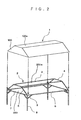
- Figs. 1(a)-1(d) are perspective views showing respective structures of embodiments of the present invention, wherein Fig. 1(a) is a perspective view showing the structure of a first embodiment of the present invention, Fig. 1(b) is a perspective view of the structure of a second embodiment of the present invention, Fig. 1(c) is a perspective view showing the structure of a third embodiment of the present invention, and Fig. 1(d) is a perspective view showing the structure of a fourth embodiment of the present invention; Fig. 2 is an explanatory perspective view of the first embodiment of the present invention; and Fig. 3(a) is a perspective view showing a framework of a variation of the first embodiment of the present invention and Fig. 3(b) is a perspective view showing a reinforcing member of the variation of the first embodiment.
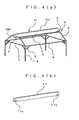
- Fig. 4(a) is a perspective view showing a framework of the second embodiment of the present invention and Fig. 4(b) is a perspective view showing a reinforcing member of the second embodiment;
- Fig. 5(a) is a perspective view showing a framework of the third embodiment of the present invention and
- Fig. 5(b) is an explanatory side view of the third embodiment;
- Fig. 6 is an explanatory perspective view of the fourth embodiment of the present invention;
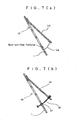
- Figs. 7(a), 7(b) are explanatory perspective views of a tie-down means of the fourth embodiment of the present invention; and
- Fig. 8 is an explanatory perspective view of the tie-down means of the fourth embodiment of the present invention.
- FIG. 9 is a schematic illustration for comparison of height between a crosswind-resistant outdoor tent, of which an awing roof has flat zenith and trapezoidal upright sides, and a conventional outdoor tent having a gable roof
- Fig. 10 is a schematic illustration for comparison of height among the crosswind-resistant outdoor tent, of which an awing roof has flat zenith and trapezoidal upright sides, the conventional outdoor tent having a gable roof, and a crosswind-resistant outdoor tent according to the third embodiment
- Figs. 11(a), 11(b) are illustrations showing a method of assembling a framework according to the present invention
- Fig. 12 is a comparative table indicating blowing-up wind pressures on tent
- Fig. 13 is a comparative table indicating blowing-up wind pressures on windward side of tent.
- numeral 1 designates an awing of the present invention with trapezoidal upright sides
- 1' designates an awing of conventional gable roof
- 2 designates a framework
- 3 designates a ridge beam
- 4 designates a side beam
- 5 designates a rafter
- 6 designates a pole plate
- 7 designates an end plate
- 8 designates a pole
- 9 designates a brace
- 10 designates a reinforcing member (side beam)
- 10a designates a hook
- 11 designates a reinforcing member (ridge beam)
- 11a designates a hook
- 11b designates a back of the reinforcing member
- 13 designates a ventilator
- 14 designates a sheet lid
- 15 designates a tie-down means
- 16 designates a rubber cord
- 17 designates a ring
- 18 designates a rubber cord
- 19 designates a waterproof sheet
- 100 designates an upright side of the awing roof
- each of crosswind-resistant outdoor tents of the present invention is an outdoor tent of a type having an awning roof at its top and open peripheral sides.
- An awing roof of the outdoor tent comprises an awing 1 and a framework 2.
- the awing roof comprises an awing 1, which includes left and right upright sides 100 which are trapezoidal, a zenith 100a which is flat, and front and rear faces which are inclined to extend downward apart from each other, and a framework 2 supporting the awing 1 and having a horizontal quadratic prism shape, which is composed of trapezoidal frames forming left and right sides 200 and four bridge beams (ridge beams 3) which are fixed at both ends to corresponding corners of the trapezoidal frames so as to extend horizontally between the trapezoidal frames.
- a zenith 200a is composed of two or three ridge beams 3 (see Figs. 5(a), 5(b)) and two side beams 4 made of metallic pipes and a roof bottom is composed of two pole plates 6 and two end plates 7 made of metallic pipes.
- the frame of the roof zenith 200a composed of the ridge beams 3 and side beams 4 and the frame of the roof bottom composed of the pole plates 6 and the end plates 7 are joined by rafters 5 made of metallic pipes.
- the framework 2 of the awing roof is supported by a plurality of (four or more) poles 8 and the framework 2 of the awing roof and the poles 8 are joined by braces 9.
- An embodiment of the present invention shown in the perspective view of Fig. 1(a) showing the structure of the first embodiment of the present invention comprises a framework 2 composed of ridge beams 3, side beams 4, rafters 5, pole plates 6, end plates 7, and poles 8, all of which are made of metallic pipes, and an awing 1 including left and right trapezoidal sides 100, a flat zenith 100a, and front and rear inclined faces extending downward apart from each other, wherein the awing 1 is put on the framework 2.
- the assembly of the framework 2 As can be seen from the illustrations in Figs. 11(a), 11(b) showing the ways of assembling the frames, the assembly of the ridge beams 3, the side beams 4, and the rafters 5 can be done by means shown in Fig. 11(a) and the fitting of the pole plates 6, the end plates 7, and the rafters 5 to the poles 8 can be done by the means shown in Fig. 11(b), that is, the both assemblies can be done by conventional means.
- the framework 2 of the awing roof having the trapezoidal sides 100 and the poles 8 supporting the framework 2 of the roof are adapted to be freely assembled or disassembled by assembling means suitable for the respective joints.
- Each brace 9 is designed such that one end thereof is always fixed to the pole 8 and the other end is attached to the pole plate 6 or the end plate 7 during the assembly of the outdoor tent, thereby reinforcing the joints between the awing roof and the poles 8 to serve for preventing the fall of the outdoor tent.
- the zenith 100a Since the awing roof 1 of which the upright sides 100 are composed of trapezoidal frames, the zenith 100a is flat, and the front and rear faces are inclined faces extending downward apart from each other according to the aforementioned structure, as shown in the schematic illustration of Fig.
- the height h1 of the awing roof of the present invention can be lower than that of the conventional gable roof 1' by 70-20%, thus not only enduring a strong gust of crosswind but also providing other effects such as enabling the construction of a tent longer depth.
- Fig. 3(a) showing a framework of a variation of the first embodiment of the present invention
- Fig. 3(b) showing a reinforcing member of the variation of the first embodiment
- one or more reinforcing members (side beams) 10 are provided to extend between the two ridge beams 3, 3 of the zenith 200a of the framework 2 to support the awing 1 (see Fig. 1(a)), preventing sag of the awing 1.
- the reinforcing member (side beam) 10 may be a hollow block made of light metal having hooks 10a to be fitted with the metallic pipes of the ridge beams 3 on the both sides thereof as shown in the perspective view of Fig. 3(b) showing the reinforcing member of the variation of the first embodiment.
- This structure is preferable because the necessity of preparing other fasteners for attaching the reinforcing member (side beam) 10 to the ridge beams 3 can be eliminated and the reinforcing member can be easily attached when needed.
- the reinforcing member 10 may be fixed by using bolts or fasteners.
- Fig. 1(b) is a perspective view of the structure of a second embodiment of the present invention.
- a crosswind-resistant outdoor tent of the second embodiment shown in Fig. 1(b) includes one or more reinforcing members (ridge beams) 11 (see Fig. 4(a)) arranged to have a projecting ridge 11b on the zenith in order to prevent rain water from collecting on the flat zenith of the awing having trapezoidal sides 100.
- Fig. 4(a) is a perspective view showing a framework of the second embodiment of the present invention and Fig. 4(b) is a perspective view showing the reinforcing member of the second embodiment.
- rain water may collect on the zenith during the rain because the zenith 100a of the awing roof is flat.
- one or more reinforcing members (ridge beams) 11 are preferably arranged to extend between the two side beams 4, 4 of the zenith 200a of the framework to have one or more projecting ridges 11b, thereby supporting the awing 1 (see Fig. 1(b)) and thus preventing sag of the awing 1.
- the reinforcing member (ridge beam) 11 may be a long block made of light metal having hooks 11a to be fitted with the metallic pipes of the side beams 4 on the both sides thereof as shown in the perspective view of Fig. 4(b) showing the reinforcing member of the second embodiment.
- This structure is preferable because the necessity of preparing other fasteners for attaching the reinforcing member (ridge beam) 11 to the side beams 4 can be eliminated and the reinforcing member 11 can be easily attached when needed.
- the reinforcing member 10 may be fixed by using bolts or fasteners.
- a projection 100b is formed in the zenith 100a.
- the formation of the projection 100b provides a structure capable of preventing rain water from collecting on the zenith 100a of the awing 1.
- Fig. 10 is a schematic illustration for comparison among the height of the crosswind-resistant outdoor tent, of which the awing roof 1 has the trapezoidal upright sides 100 and the flat zenith 100a, the height of the conventional outdoor tent having the gable roof 1', and the height (the apex of the projection 100b) of the crosswind-resistant outdoor tent according to the second embodiment.
- the height h1b of the crosswind-resistant outdoor tent of the second embodiment can be lower than that of the conventional gable roof 1' by 70-20%, thus not only preventing rain water from collecting, but also enduring a strong gust of crosswind and further providing other effects such as enabling the construction of a tent longer depth.
- Fig. 1(c) is a perspective view showing the structure of a third embodiment of the present invention.
- a crosswind-resistant outdoor tent of the third embodiment shown in Fig. 1(c) has a convex portion provided in the zenith 100a so as to form a triangle zenithw sides 100d in order to prevent rain water from collecting on the flat zenith 100a (see Fig. 1(a)) of the awing 1 having the trapezoidal sides 100.
- Fig. 5(a) is a perspective view showing a framework of the third embodiment of the present invention.
- rain water may collect on the zenith during the rain because the zenith 100a of the awing roof is flat and therefore the awing 1 may sag. Consequently, as shown in Fig. 5(b), by providing the convex portions on the upper edges of the sides 200 of the framework 2 to form triangles 200c, respectively, and arranging the ridge beam 3 (see Fig.
- the convex portions 200b are formed at the zenith 200a of the framework, thereby supporting the awing (see Fig. 1(c)) and thus preventing sag of the awing 1 due to rain water or the like.
- FIG. 1(d) is a perspective view showing the structure of a fourth embodiment of the present invention.
- a crosswind-resistant outdoor tent of the fourth embodiment shown in Fig. 1(d) is the same crosswind-resistant outdoor tent of the aforementioned third embodiment except that the awing roof is provided with a ventilator 13 comprising a plurality of openings formed adjacent to each other and with a sheet lid 14 for covering the ventilator 13 of which an upper edge is fixed to a portion about the center of the zenith 100a of the awing roof by sewing or adhesive bonding and the opposite side edge is connected to portions near the awing edges adjacent to the ventilator 13 by one or more tie-down means 15.
- the tie-down means 15 exhibit moderate fixing strength so that the lid 14 is adapted to automatically open when subjected to gust or big wind to prevent the awing 1 from being blown away.
- the crosswind-resistant outdoor tent according to the fourth embodiment is structured such that when crosswind (arrow) is blowing as shown in the explanatory perspective view of Fig. 6 showing the fourth embodiment of the present invention, wind passes through the ventilator 13 to push up the sheet lid 14 and thus passes away, reducing the blowing up wind pressure applied on the awing roof by the crosswind.
- the ventilator 13 is composed of a plurality of circular openings in this embodiment, the shape of the openings is not limited to circle and the number of the openings may be one or more. In addition, the number of the sheet lids 14 arranged outside of the ventilator 13 may be one or more. Any suitable configuration capable of reducing the flowing up pressure on the awing roof may be employed.
- the ventilators 13 are formed to have such shape, number, and width that the portions of the awing roof remaining between adjacent openings can retain strength of the awing roof and the ventilators 13 are formed to have such size that the total area of the ventilators 13 allow the lid(s) 14 to open when subjected to gust or big wind.
- the sheet lid 14 is preferably made of waterproof material.
- the sheet lid 14 is preferably made of the same material as that of the awing 1 such as sail cloth.
- the corner edges of the sheet lid 14 of the crosswind-resistant outdoor tent according to the fourth embodiment of the present invention are preferably connected to portions near the shorter awing edges adjacent to the ventilator 13 by one or more tie-down means 15 which exhibit moderate fixing power.
- the tie-down means 15 may be means allowing a part or parts of the corner edge adjacent to the ventilator 13 to be free, means comprising a hook-and-loop fastener, or means using attraction of magnet, further alternatively, means of tying down the both lower ends of the lid 14 via rubber cords 16 as shown in the explanatory perspective view of Fig.
- FIG. 7(a) showing a tie-down means of the fourth embodiment, or means of connecting portions near the both lower ends of the ventilator 13 and the both lower ends of the lid 14 via rubber cords 18 passing through and stopped at both ends thereof by rings 17 made of cord, metal, or plastic fixed to the both lower ends of the lid 14 and fixed to portions of the awing 1 around the both lower corner edges of the ventilator 13 as shown the explanatory perspective view of Fig. 7(b) showing a tie-down means of the fourth embodiment.
- the rubber cord 18 is preferably arranged to have such a length that the lid 14 is blown up by gust or big wind to a level required to allow wind pressure to escape through the ventilator 13.
- the left and right side edges of the sheet lid 14 may be fixed via expansible waterproof sheets 19 comprising bellows arranged at the left and right ends of the ventilator 13, thereby preventing rain water from entering into the tent through the left and right ends of the ventilator 13 when the lid 14 opens.
- the area ratio between the ventilator 13 and the lid 14 covering the ventilator 13 in the embodiment is defined to take account of the degree of entering rain water when the lid 14 is blown up by gust or big wind during the rain. It is preferable to employ the means using expansible waterproof sheets 19 comprising bellows arranged at the left and right side edges of the ventilator 13 to fix the left and right corner edges of the sheet lid 14 so as to prevent rain water from entering into the tent through the left and right ends of the ventilator 13 when the lid 14 opens.
- the fourth embodiment of the present invention shown in Fig. 1(d) is the same crosswind-resistant outdoor tent of the aforementioned third embodiment except that the awing roof is provided with a ventilator 13 comprising a plurality of openings formed adjacent to each other and with a sheet lid 14 for covering the ventilator 13 of which an upper edge is fixed to portions about the center of the zenith 100a of the awing roof by sewing or adhesive bonding and the opposite side edge is connected to portions near the awing edges adjacent to the ventilator 13 by one or more tie-down means 15 capable of exhibiting moderate fixing strength.
- the crosswind-resistant outdoor tent of the first embodiment and the crosswind-resistant outdoor tent of the second embodiment may be also to have the same structure that a ventilator 13 comprising one opening or ventilator(s) 13 comprising a plurality of openings are formed and one or more sheet lids 14 are provided to cover the ventilators 13 such that the upper edges are fixed to portions about the center of the zenith 100a of the awing roof by sewing or adhesive bonding and the opposite side edges are connected to portions near the awing edges adjacent to the ventilator 13 by one or more tie-down means 15 capable of exhibiting moderate fixing strength so that the lids 14 are adapted to automatically open when subjected to gust or big wind to prevent the awing 1 from being blown away.
- ventilator 13 is formed near the zenith 100a in the fourth embodiment of the present invention shown in Fig. 1(d), ventilators 13 may be formed in left and right upright sides of the awing roof and sheet lids 14 may be fixed according to the installation place and/or environment of the crosswind-resistant outdoor tent.
- Fig. 12 provides a comparative table indicating blowing-up wind pressures on tent and Fig. 13 provides a comparative table indicating blowing-up wind pressure on windward side of tent.
- the comparative tables indicate blowing-up wind pressures on tent and blowing-up wind pressure on windward side of tent, these values were measured with wind velocity of 5-20 m/s in case of a conventionally used outdoor tent having a gable roof of which right and left upright sides are triangle in shape (conventional gable roof type), an outdoor tent of the aforementioned third embodiment with a roof of which right and left upright sides are trapezoidal in shape and having a convex portion arranged on the zenith such that the sides of the zenith are triangle in shape (trapezoidal roof type: without sheet lids), and an outdoor tent of the aforementioned fourth embodiment with a roof of which right and left upright sides are trapezoidal in shape and having a convex portion arranged on the zenith such that the sides of the zenith are triangle in shape and a plurality of ventilators 13 formed near the zenith (trapezoidal roof type: with sheet lids).
- the tables also indicate rates of improvement with regard to the blowing-up wind pressures on tent and fall-resisting properties, that is "NG” if fell or “OK” if endured against falling with regard to the blowing-up wind pressures on windward side of tent.
- the highest blowing-up wind pressure was a value in case of the tent of conventional gable roof type
- the next highest blowing-up wind pressure was a value in case of the tent of trapezoidal roof type (without sheet lids)
- the lowest blowing-up pressure was a value in case of the tent of trapezoidal roof type (with sheet lids) as shown in the comparative table of Fig. 12 indicating blowing-up wind pressures on tent.
- the rate of improvement of the tent of trapezoidal roof type without sheet lids was 74.5%, and the rate of improvement of the tent of tent of trapezoidal roof type with sheet lids was 72.4-66.0%, that is, it is found that the blowing-up wind pressure was reduced by about 45%.
- the highest blowing-up wind pressure was a value in case of the tent of conventional gable roof type
- the next highest blowing-up wind pressure was a value in case of the tent of trapezoidal roof type (without sheet lids)
- the lowest blowing-up pressure was a value in case of the tent of trapezoidal roof type (with sheet lids) as shown in the comparative table of Fig. 13 indicating blowing-up wind pressure on windward side of tent.
Landscapes
- Engineering & Computer Science (AREA)
- Architecture (AREA)
- Civil Engineering (AREA)
- Structural Engineering (AREA)
- Tents Or Canopies (AREA)
Applications Claiming Priority (3)
| Application Number | Priority Date | Filing Date | Title |
|---|---|---|---|
| JP2002378414 | 2002-12-26 | ||
| JP2002378414 | 2002-12-26 | ||
| PCT/JP2003/017028 WO2004059106A1 (fr) | 2002-12-26 | 2003-12-26 | Tente en toile resistant au vent lateral |
Publications (1)
| Publication Number | Publication Date |
|---|---|
| EP1577462A1 true EP1577462A1 (fr) | 2005-09-21 |
Family
ID=32677428
Family Applications (1)
| Application Number | Title | Priority Date | Filing Date |
|---|---|---|---|
| EP03768361A Withdrawn EP1577462A1 (fr) | 2002-12-26 | 2003-12-26 | Tente en toile resistant au vent lateral |
Country Status (8)
| Country | Link |
|---|---|
| US (1) | US20050081904A1 (fr) |
| EP (1) | EP1577462A1 (fr) |
| JP (1) | JP3797377B2 (fr) |
| KR (1) | KR20050089852A (fr) |
| CN (1) | CN1732321A (fr) |
| AU (1) | AU2003292712A1 (fr) |
| BR (1) | BR0317213A (fr) |
| WO (1) | WO2004059106A1 (fr) |
Families Citing this family (21)
| Publication number | Priority date | Publication date | Assignee | Title |
|---|---|---|---|---|
| US20060169309A1 (en) * | 2005-01-22 | 2006-08-03 | Eastman Holding Company | Outdoor enclosure with magnetic flap closure |
| US20100258151A1 (en) * | 2007-08-31 | 2010-10-14 | Vogt Jeffrey A | Wind-resistant umbrella |
| US20090056883A1 (en) * | 2007-08-31 | 2009-03-05 | Vogt Jeffrey A | Wind resistant awning |
| US20090056884A1 (en) * | 2007-08-31 | 2009-03-05 | Vogt Jeffrey A | Wind resistant awning |
| US7784480B2 (en) | 2007-09-13 | 2010-08-31 | Bravo Sports | Canopy with ventilation |
| WO2013116545A1 (fr) * | 2012-02-03 | 2013-08-08 | Bravo Sports | Structure de tonnelle |
| US9103138B2 (en) | 2012-10-02 | 2015-08-11 | Bravo Sports | Sliding-eave mount mechanism for canopy structure |
| US9683387B2 (en) | 2012-12-07 | 2017-06-20 | Bravo Sports | Canopy shelter link point |
| USD736884S1 (en) | 2013-07-16 | 2015-08-18 | Bravo Sports | Adjustable locking leg assembly |
| US9528292B1 (en) | 2013-08-09 | 2016-12-27 | Bravo Sports | Canopy with overhang |
| US9395514B2 (en) | 2013-11-04 | 2016-07-19 | Skyfuel, Inc. | Pyramidal space frame and associated methods |
| US9797157B2 (en) | 2014-03-04 | 2017-10-24 | Shelterlogic Corp. | Canopy with detachable awning |
| USD737066S1 (en) | 2014-03-06 | 2015-08-25 | Bravo Sports | Chair with integrated shade cover |
| CN104258516B (zh) * | 2014-10-14 | 2017-02-22 | 中国中元国际工程有限公司 | 罩式消防作业防护装置 |
| US9867466B2 (en) | 2014-12-15 | 2018-01-16 | Shelterlogic Corp. | Foldable chair |
| JP6784460B2 (ja) * | 2016-05-19 | 2020-11-11 | 嘉織 大津 | ダクトの構造 |
| CN107047134A (zh) * | 2017-05-17 | 2017-08-18 | 天津大学 | 一种大棚结构补气装置 |
| KR102041562B1 (ko) | 2018-04-19 | 2019-12-02 | 이병협 | 영어도서관 온라인 리딩 코칭 시스템 및 학습방법 |
| CN208456255U (zh) * | 2018-06-26 | 2019-02-01 | 常州新亚奥特多金属制品有限公司 | 一种通风型帐篷 |
| CN108684340A (zh) * | 2018-07-25 | 2018-10-23 | 青岛市农业科学研究院 | 一种甘薯贮藏窖 |
| KR102253768B1 (ko) | 2019-04-03 | 2021-05-24 | 장호열 | 의료영상 리코딩 시스템 및 리코딩 로봇의 제어 방법 |
Family Cites Families (20)
| Publication number | Priority date | Publication date | Assignee | Title |
|---|---|---|---|---|
| US39416A (en) * | 1863-08-04 | Improvement in ventilating-caps for tents | ||
| US1124263A (en) * | 1908-07-25 | 1915-01-12 | John Bentley Bemis | Collapsible tent. |
| US1003370A (en) * | 1911-03-16 | 1911-09-12 | Minerva E Priest | Screen. |
| US1428343A (en) * | 1921-09-01 | 1922-09-05 | Runcie William Thackeray | Tent ventilator |
| US2036482A (en) * | 1934-11-17 | 1936-04-07 | Philip R S Larson | Elastic shoe lace |
| US3233617A (en) * | 1961-11-30 | 1966-02-08 | Morton M Rosenfeld | Temporary enclosure |
| US3456661A (en) * | 1967-02-13 | 1969-07-22 | Francois C Vigier | Windproof umbrella |
| JPS48107506U (fr) * | 1972-03-15 | 1973-12-13 | ||
| JPS5349550Y2 (fr) * | 1976-01-09 | 1978-11-28 | ||
| JPS5914547U (ja) * | 1982-07-21 | 1984-01-28 | 渡辺パイプ株式会社 | 栽培用ハウス |
| JPS5975803U (ja) * | 1982-11-12 | 1984-05-23 | 鈴木 義雄 | 組立式雨覆い |
| JPH0331806Y2 (fr) * | 1985-06-19 | 1991-07-05 | ||
| JPH082331Y2 (ja) * | 1989-04-08 | 1996-01-24 | 東洋ゴム工業株式会社 | 膨脹式テント |
| US5115828A (en) * | 1991-03-18 | 1992-05-26 | Shaffer Tent & Awning Co. | Demountable frame structure |
| SE9102285L (sv) * | 1991-08-05 | 1992-10-26 | Svensson Ludvig Int | Vaevt insektsnaet foer avskaerning av luftpassage |
| JPH0666053A (ja) * | 1992-08-21 | 1994-03-08 | Chisso Corp | 風孔を設けたテント |
| JPH09125747A (ja) * | 1995-10-27 | 1997-05-13 | Kaijirushi Hamono Kaihatsu Center:Kk | テントカバーにおける通風構造 |
| US5711337A (en) * | 1996-05-15 | 1998-01-27 | Mckenney; Joseph E. | Tent frame and party tent |
| JP2002004643A (ja) * | 2000-06-16 | 2002-01-09 | Sekisui House Ltd | テント |
| US6662816B1 (en) * | 2002-06-17 | 2003-12-16 | George C. Cunningham | Canopy vent |
-
2003
- 2003-12-26 JP JP2004562960A patent/JP3797377B2/ja not_active Expired - Fee Related
- 2003-12-26 WO PCT/JP2003/017028 patent/WO2004059106A1/fr not_active Ceased
- 2003-12-26 CN CN200380107587.6A patent/CN1732321A/zh active Pending
- 2003-12-26 AU AU2003292712A patent/AU2003292712A1/en not_active Abandoned
- 2003-12-26 KR KR1020057011940A patent/KR20050089852A/ko not_active Ceased
- 2003-12-26 BR BR0317213-9A patent/BR0317213A/pt not_active IP Right Cessation
- 2003-12-26 EP EP03768361A patent/EP1577462A1/fr not_active Withdrawn
- 2003-12-26 US US10/501,091 patent/US20050081904A1/en not_active Abandoned
Non-Patent Citations (1)
| Title |
|---|
| See references of WO2004059106A1 * |
Also Published As
| Publication number | Publication date |
|---|---|
| JPWO2004059106A1 (ja) | 2006-04-27 |
| JP3797377B2 (ja) | 2006-07-19 |
| AU2003292712A1 (en) | 2004-07-22 |
| BR0317213A (pt) | 2005-11-01 |
| WO2004059106A1 (fr) | 2004-07-15 |
| US20050081904A1 (en) | 2005-04-21 |
| CN1732321A (zh) | 2006-02-08 |
| KR20050089852A (ko) | 2005-09-08 |
Similar Documents
| Publication | Publication Date | Title |
|---|---|---|
| EP1577462A1 (fr) | Tente en toile resistant au vent lateral | |
| US6550189B2 (en) | Weather shelter | |
| US5218982A (en) | Handy hut | |
| US5711337A (en) | Tent frame and party tent | |
| US20040261953A1 (en) | Sail shaped awnings | |
| US20090293927A1 (en) | Shelter having an extendable roof | |
| EP0795068A1 (fr) | Systeme de protection temporaire | |
| US10858856B1 (en) | Modular tent construction and components thereof | |
| CA2731430C (fr) | Tente en forme de selle avec portique | |
| CN100529289C (zh) | 轻型木制天幕结构运动场馆 | |
| Llorens | Detailing masts | |
| CA2961600A1 (fr) | Tente structurale et procede de montage | |
| US20070245639A1 (en) | Circular building structure and method of constructing the same | |
| JP2623072B2 (ja) | ドーム型仮設テントとその組立方法 | |
| JP2008214962A (ja) | 災害救護用応急仮設テントハウス | |
| KR101044156B1 (ko) | 게이트볼장의 구조물 | |
| EP0654114B1 (fr) | Dispositif a assemblage libre a structure a parois verticales constituant un garde-fou | |
| JP2006090124A (ja) | 横風対応型野外テント | |
| KR200379642Y1 (ko) | 건축물 공사용 보온 덮개 지붕틀 | |
| CN218815609U (zh) | 帐篷结构组件 | |
| KR200278454Y1 (ko) | 내풍텐트의 지지구조 | |
| JPH06330639A (ja) | 開閉機構を備えた仮設テント | |
| KR20260007914A (ko) | 몽골 텐트 또는 캐노피 텐트용 프레임 연결장치 | |
| CN206328976U (zh) | 一种遮阳雨棚装置 | |
| JPS6329083Y2 (fr) |
Legal Events
| Date | Code | Title | Description |
|---|---|---|---|
| PUAI | Public reference made under article 153(3) epc to a published international application that has entered the european phase |
Free format text: ORIGINAL CODE: 0009012 |
|
| 17P | Request for examination filed |
Effective date: 20050719 |
|
| AK | Designated contracting states |
Kind code of ref document: A1 Designated state(s): AT BE BG CH CY CZ DE DK EE ES FI FR GB GR IE IT LI LU MC NL PT RO SE SI SK TR |
|
| AX | Request for extension of the european patent |
Extension state: AL LT LV MK |
|
| RTI1 | Title (correction) |
Free format text: CROSSWIND-RESISTANT OUTDOOR TENT |
|
| DAX | Request for extension of the european patent (deleted) | ||
| RBV | Designated contracting states (corrected) |
Designated state(s): CH DE FR GB LI |
|
| STAA | Information on the status of an ep patent application or granted ep patent |
Free format text: STATUS: THE APPLICATION HAS BEEN WITHDRAWN |
|
| 18W | Application withdrawn |
Effective date: 20080513 |