EP1577575A1 - Lamellenkupplung - Google Patents
Lamellenkupplung Download PDFInfo
- Publication number
- EP1577575A1 EP1577575A1 EP04006276A EP04006276A EP1577575A1 EP 1577575 A1 EP1577575 A1 EP 1577575A1 EP 04006276 A EP04006276 A EP 04006276A EP 04006276 A EP04006276 A EP 04006276A EP 1577575 A1 EP1577575 A1 EP 1577575A1
- Authority
- EP
- European Patent Office
- Prior art keywords
- plate
- radius
- back plate
- clutch according
- actuator
- Prior art date
- Legal status (The legal status is an assumption and is not a legal conclusion. Google has not performed a legal analysis and makes no representation as to the accuracy of the status listed.)
- Granted
Links
Images




Classifications
-
- F—MECHANICAL ENGINEERING; LIGHTING; HEATING; WEAPONS; BLASTING
- F16—ENGINEERING ELEMENTS AND UNITS; GENERAL MEASURES FOR PRODUCING AND MAINTAINING EFFECTIVE FUNCTIONING OF MACHINES OR INSTALLATIONS; THERMAL INSULATION IN GENERAL
- F16D—COUPLINGS FOR TRANSMITTING ROTATION; CLUTCHES; BRAKES
- F16D13/00—Friction clutches
- F16D13/22—Friction clutches with axially-movable clutching members
- F16D13/38—Friction clutches with axially-movable clutching members with flat clutching surfaces, e.g. discs
- F16D13/52—Clutches with multiple lamellae ; Clutches in which three or more axially moveable members are fixed alternately to the shafts to be coupled and are pressed from one side towards an axially-located member
-
- F—MECHANICAL ENGINEERING; LIGHTING; HEATING; WEAPONS; BLASTING
- F16—ENGINEERING ELEMENTS AND UNITS; GENERAL MEASURES FOR PRODUCING AND MAINTAINING EFFECTIVE FUNCTIONING OF MACHINES OR INSTALLATIONS; THERMAL INSULATION IN GENERAL
- F16D—COUPLINGS FOR TRANSMITTING ROTATION; CLUTCHES; BRAKES
- F16D13/00—Friction clutches
- F16D13/58—Details
- F16D13/60—Clutching elements
- F16D13/64—Clutch-plates; Clutch-lamellae
- F16D13/648—Clutch-plates; Clutch-lamellae for clutches with multiple lamellae
Definitions
- the invention relates to a multi-plate clutch according to the preamble of claim 1
- multi-plate clutches are known from the prior art a variety of modifications known.
- a typical embodiment is shown in the drawing figure 25.
- the In the figure 25 shown multi-plate clutch comprises a External disk carrier 1, an inner disk carrier 2, outer disks 4, 5, 6 7, inner disks 10, 11, 12, 13 (with friction linings) and a back plate 8.
- the outer disk carrier 1 and the inner disk carrier 2 are rotatable about a common axis of rotation ax.
- the outer plates 4, 5, 6, 7 are rotatably supported by the outer disk carrier 1.
- the outer plates 4, 5, 6, 7 a External toothing, which in a corresponding internal toothing of the outer disk carrier 1 engages.
- the inner disks 10, 11, 12, 13 with the inner disk carrier 2 rotatably connected.
- the inner plates 10, 11, 12, 13 on the inner peripheral side a toothing, which in a corresponding external toothing of the inner disk carrier 2 engages.
- Outer and inner plates 4, 5, 6, 7, 10, 11, 12, 13 and also one in the internal toothing the outer disk carrier 1 engaging outer teeth having Back plate 8 are axially displaceable in this way guided on the respective plate carriers 1, 2.
- Outer and inner plates 4, 5, 6, 7, 10, 11, 12, 13 and the Back plate 8 are arranged axially next to each other, wherein in each case a supported by the outer disk carrier 1 outer disk 4, 5, 6, 7 and one supported by the inner disk carrier 2 Inner plate 10, 11, 12, 13 arranged adjacent to each other are.
- the supported by the outer disk carrier 1 back plate 8 is adjacent to that carried by the inner disk carrier 2 Inner plate 13 is arranged.
- Outer and inner plates 4, 5, 6, 7, 10, 11, 12, 13 form in this way a disk set.
- the multi-plate clutch is actuated by means of an axially movable actuator 3 (usually a hydraulically actuated piston) in which it presses against the lamella nearest to it, in the present case an outer lamella 4.
- the back plate 8 is supported in the example via a retaining ring 9 against the outer disk carrier 1 from to receive the contact force F A of the axially movable actuator 3.
- the object of the invention now lies in a multi-plate clutch in a manner known per se in such a way and to develop further, that a local overheating and overpressure of the Friction elements is reduced.
- the invention now proceeds from a multi-plate clutch per se known type, with a rotatable about a rotation axis Outer plate carrier carried outer plates and with of one Inner lamellae supported about the rotation axis rotatable inner lamella carrier, wherein the outer plates and the inner plates a Form the slat package. Further, an axially movable actuator provided, which when pressed on a middle Force application radius with respect to the axis of rotation a contact pressure on a plate forming a pressure plate of the disk pack transfers.
- the actuator 3 has a ring crest 20 at an optimum force application radius r FA0 .
- the force application takes place here approximately on a circumferential line with the force attack radius r FA0 , which coincides with the average force application radius r FA of the actuator 3 according to the above definition.
- the multi-plate clutch from which the invention proceeds further comprises a back plate, which transmits an opposing force to a plate forming a counter plate of the disk set upon actuation of the actuator on an average force application radius r FR of the back plate with respect to the axis of rotation ax.
- the slats When operating the actuator, the slats are frictionally engaged Contact with a medium effective friction radius spent while transmitting a torque.
- the invention is now based on the analysis of the cause of the observed overheating effects:
- the axial contact force F A of the actuator 3 is passed through the pressure plate 4 through the entire disk set.
- the components typically deform in a slender manner by amounts of up to a few tenths of a millimeter.
- the back plate 8 as in the exemplary embodiment according to FIG. 25 , is supported on the outer radius r a , then it experiences an overturning moment which acts in such a way that it deviates to the right at the inner radius r i .
- the back plate were supported on the inner radius r i , it would experience an overturning moment in such a way that it would be bent to the right at its outer radius r a .
- the invention is now based on the idea, the pressure distribution especially at high contact pressures to uniform or to optimize with regard to the friction losses.
- the invention is therefore in a generic multi-plate clutch provided that the ratio of the average force application radii to the mean friction radius with a contact force, which roughly corresponds to a transmission of the nominal torque necessary nominal contact pressure, smaller or is 1 and greater than 0.97. This ensures that at high contact forces a uniform distribution of surface pressure or the friction in the disk pack occurs. Local overheating can no longer occur in this way.
- the ratio the average load radii for the middle friction radius at the contact pressure which is approximately the Nennanpresskraft corresponds to greater than 0.99, preferably 0.997.
- the average force radii are in the aforementioned contact pressure, which is approximately the Nennanpresskraft corresponds, identical or nearly identical. In this way one achieves that in all slats almost the same surface pressure distribution and thus also almost the same heat distribution prevails.
- the back plate radially outside the mean friction radius has a clearance angle surface when they axially supported on the outer disk carrier or that the Back plate radially within the middle Reibradius a Free-angle surface, when axially on the inner disk carrier is supported.
- the clearance angle surface is conical in the simplest case. However, it can also be curved concave or convex or be formed stage.
- the back plate and / or the actuator one with the pressure plate or the counter plate when actuated in operative connection having kicking ring tip or have ring crests.
- Appropriate Clearance surfaces are inevitable in this way available.
- This variant has the further advantage that the respective force application radius comparatively exactly predetermined becomes. Such a variant is then permissible and possible if the deflection of the Andrucklamellen or the Counter plate is held in a reasonable frame. In In some applications, however, it is better to have a larger surface Force entry to specify.
- the concentration on the inner radius area leads to a smaller effective friction radius, hereby at a certain Axial force to a smaller transmitted friction torque and thus in addition to the benefit of a smaller "clutch gains" at low pressures.
- the middle Force application radius of the actuator and / or the average force application radius the back plate at a contact pressure which in about up to 30%, preferably about up to 5% to 15% of the Nominal contact pressure equals between the middle friction radius and an inner radius of the friction surfaces of the lamellae or lie.
- the average force application radius of the actuator and / or the average force application radius of the back plate at a contact pressure which is approximately up to 30%, preferably approximately up to 5% to 15% of the nominal contact pressure, between the mean friction radius and an outer radius of Friction surfaces of the slats lie or lie.
- the average force application radius of the actuator and / or the average force application radius the back plate at the aforementioned contact force from about up to 30%, preferably up to about 5% 15% of the nominal contact pressure in the inner fifth between the Friction radius and the inner radius of the friction surfaces of the slats too choose.
- the average force application radius lies or lies of the actuator and / or the average force application radius the back plate at this contact pressure on the inner Radius of the friction surfaces of the slats.
- the at least one clearance angle surface is conical educated.
- conical shape can also be any other Shape, in particular a concave or convex or stepped Form are chosen, with a stepped shape with higher Accuracy is to produce as a cone shape.
- the back plate and / or the actuator one with the pressure plate or the counter-plate
- the Ringkuppe or the Ringkuppen is or are in place the corresponding average force application radius at the low Contact force arranged. This is at high contact pressures in the vicinity of the nominal contact force is suppressed, so that the contact forces of both the actuator and the back plate with high amounts at the middle load radii attack, which is essentially the mean friction radius correspond.
- the invention advantageously provides a resilient element on the actuator and / or the Back plate in front of which at a contact force which approximately up to 30%, preferably up to about 5% to 15% of the Nominal contact force corresponds to the contact pressure at the inner or transmits or transmits near the inner radius.
- a resilient element provided on the actuator and / or the back plate, which at a contact pressure which in about up to 30%, preferably approximately up to 5% to 15% of the nominal contact force, the contact pressure at the outer or near the outer radius transmits or transmits.
- the pressure plate or the counter plate with a equip such resilient element it is made of manufacturing technology Reasons more meaningful, the resilient element on Provide actuator.
- the resilient element or the resilient elements may disc springs, Coil springs or other elastic elements be. It is also possible that the resilient element or the resilient elements by a corresponding shaping of the actuator and / or the back plate is or are formed.
- the back plate in the axial half section be hook-shaped with a radially in the region of inner radius arranged fingers and a radial in the area of the middle friction radius arranged knee.
- the knee is there preferably up to a contact pressure of about 30%, preferably from about 5% to 15% of the nominal contact force of the backing plate spaced, while the finger in the area of the inner Radius is seated.
- the back plate in the axial half-section hook-shaped be arranged with a radially in the region of the outer radius Finger and a radial in the range of the middle friction radius arranged knees.
- the knee is preferably up to a contact pressure of about 30%, preferably about 5% spaced up to 15% of the nominal contact force from the counterplate, while the finger sits in the area of the outer radius.
- the actuator may, for example, in the axial half-section L-shaped be formed and an inner leg, which in the Area of the inner radius is located, as well as a radial in the area Having the middle friction radius arranged knee.
- the actuator may be be formed in the axial half-section L-shaped and a outer leg, which is in the area of the outer radius is located, as well as a radial in the region of the central friction radius have arranged knee.
- the knee is preferably up to a contact pressure of about 30%, preferably from about 5% to 15% of the nominal contact pressure spaced from the pressure plate.
- the inner thigh is sitting in the region of the inner radius of the pressure plate at this contact pressure on the outer leg of the alternative embodiment sits in the area of the outer radius of the pressure plate at this contact pressure.
- the back plate is supported by a retaining ring against the plate carrier, with the back plate rotatably connected.
- the multi-plate clutch both in terms of high contact pressures in the area the Nennanpresskraft as well as in terms of small Torques at a contact force, which is approximately up to 30 %, preferably up to about 5% to 15% of the nominal contact pressure, optimized by, on the one hand, the ratio of the average Force radii for the middle friction radius at a contact pressure, which roughly corresponds to a transmission of the nominal torque necessary Nennanpresskraft corresponds, smaller or equal to 1 and greater than 0.97, and that, on the other hand the average force application radius of the actuator and / or the average force application radius of the back plate at a contact pressure, which in about up to 30%, preferably about to to 5% to 15% of the nominal contact pressure, between average friction radius and an inner radius of the friction surfaces the lamellae lies or lie alternatively between the mean friction radius and an outer radius of the friction surfaces the slats lie or lie.
- the multi-plate clutch can be any preferred embodiment of Multi-disc clutch, which is optimized for high contact forces, with each preferred embodiment of the multi-plate clutch, which is optimized for low contact forces combined become.
- Multi-disc clutch according to the prior art includes this inventive coupling an outer disk carrier 1, a Inner plate carrier 2, outer plates 4, 5, 6, 7, and inner plates 10, 11, 12, 13 (with friction linings), an actuator 3 and a back plate 14. All components have the same Function, as in the coupling shown in Figure 25. It is not essential to the invention that the friction linings on the inner plates 10, 11, 12, 13 are arranged. Alternatively you can the friction linings also on the outer plates 4, 5, 6, 7 or alternately on the outer and inner disks 4, 5, 6, 7, 10, 11, 12, 13 may be arranged.
- the invention is now based on the idea to equalize the pressure distribution at high axial force by the deformation of the back plate is kept.
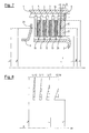
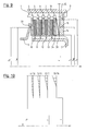
- One way to do this is the training of a z. B. conical clearance angle surface at an angle " ⁇ " outside the optimal force application radius r FA0 , as shown in Figure 1 on the back plate 14.
- the back plate 14 Under the axial force “F A ", the back plate 14 will deflect slightly, so that its ring tip 15 formed by the clearance angle surface acts as a force application line at the radius r FR .
- an additional outer plate 16 which acts as a counter plate used.
- the back plate can also be provided with a stepped clearance angle surface. Stepped clearance surfaces are easier to manufacture than tapered clearance surfaces.
- FIG. For ease of reference, like reference numerals are used as in the embodiment of FIG. 1 for like parts.
- a step-shaped back plate 32 is arranged on the outer disk carrier 1. The back plate 32 is supported via the retaining ring 9 against the outer disk carrier 1 to receive the force F A of the axially movable actuator 3. In this case, a ring crest 15 formed by the step acts as a force application radius.
- the additional outer plate 16 is used in this embodiment, which acts as a counter-plate.
- FIG. 4 shows the surface pressure distribution for that shown in FIG 3 illustrated embodiment of the multi-plate clutch with the step-shaped back plate 32. Also in this design one obtains a symmetrical pressure distribution over the whole Coupling length, d. H. the pressure between lamellas 13 and 16 is identical to the pressure between blades 4 and 10th
- the back plate may also be attached to the inner disk carrier 2.
- the plate pack of the illustrated multi-plate clutch is formed from outer plates 104, 105, 106 and 107 and inner plates 110, 111, 112 and 113.
- the outer plates 104, 105, 106 and 107 are coated with a friction lining.
- a back plate 114 with a free angle surface formed at an angle " ⁇ " is secured to the inner disk carrier 2 and is supported via a locking ring 135 against the inner disk carrier 2 to receive the force F A of the axially movable actuator 3.
- a ring tip 115 formed by the clearance angle surface acts as a force application line.
- an additional inner fin 133 is inserted between the outer fin 107 and the back plate 114.
- the surface pressure distributions of the two in FIGS. 5 and 6 illustrated embodiment corresponds to high Axial force of the surface pressure distribution according to Figure 2 or FIG. 4.
- a back plate 17 receives in this embodiment, two clearance angle surfaces under the clearance angles " ⁇ " and " ⁇ ".
- F A "F AN the contact with additional outer lamella 16 acts predominantly at the inner radius r i , with larger contact forces at the radius r FR ⁇ r 0 .
- F A ⁇ 5-15% x F AN a surface pressure p (r) will thus be formed, as shown in FIG.
- the multi-plate clutch shown in Figure 9 is constructed analogously to the multi-plate clutch shown in Figure 1, so that the same parts are provided with the same reference numerals.
- this embodiment of the multi-plate clutch on a resilient element 34 for example a plate spring, which is arranged between the counter-plate acting as additional inner plate 16 and the back plate 14 with a clearance angle surface.
- the resilient element 34 is located on the inner radius r i of the friction surfaces on the back plate 14, while it bears against the outer radius r a of the friction surfaces on the counter-plate 16.
- the resilient member 34 may jointly- r i of the friction surfaces and extend into the teeth of the inner disc carrier (not shown) in an alternative embodiment also the inner radius.
- Such a configuration has the advantage that a spring element formed as a plate spring can not move in the circumferential direction when the coupling is open, so that harmful wear on the surrounding components is avoided.
- the embodiment shown in Figure 13 corresponds a kinematic reversal of the embodiment shown in Figure 9.
- the multi-plate clutch is like the multi-plate clutch constructed of the embodiment in Figure 5, so that for simplified reference the same components with the same reference numerals are provided.
- the back plate 114 with a clearance angle surface is fixed to the inner disk carrier 2 and is supported on the inner disk carrier 2 via the securing ring 135.
- the counter-plate 133 is also arranged on the inner disk carrier 2.
- a resilient element 134 is arranged, which is realized for example by a plate spring.
- the resilient element 134 lies on the outer radius r a of the friction surfaces on the back plate 114, while it rests on the inner surface of the friction surfaces r i on the back plate 133.
- a surface pressure distribution according to FIG. 14 results, in which at small contact forces F A "F AN the contact with lamella 133 acts predominantly on the inner radius r i .
- Figure 21 is constructed substantially analogous to the embodiment of Figure 6, in addition between the stepped back plate 132 which is disposed on the inner plate carrier 2, and the Additional inner fin 133 a resilient element 134, for example, a plate spring disposed.
- the additional lamella 133 is followed by the outer lamella 107, which in this embodiment is equipped with a friction lining.
- the resilient member 134 may alternatively be configured such that it r at the inner radius i of the friction surfaces on the counter plate 133 is applied, while it extends radially outwardly extending and only up to about to the radius r 0 is resting on the step of the stepped back plate 132nd
- FIG. 23 shows a development of the exemplary embodiment according to FIG. 9, in which instead of the back plate 14 with a clearance angle surface, the stepped back plate 32 is arranged on the outer disk carrier 1, while between the counter plate 16 and the stepped back plate 32 the resilient element 34 is again arranged such that it rests on the inner radius r i of the friction surfaces on the back plate 32, while it rests against the outer radius r a of the friction surfaces on the counter plate 16.
- a friction disc designed as a resilient element 134 (see. Figure 24).
- the acting as a resilient element 134 inner plate is in the example equipped with a friction lining, of course the friction lining may also be arranged on the outer disks can.
- the situation can be further improved even if the actuator or pressing piston 23 on the left side receives a variable force application radius.
- This is outlined in FIG. 15, wherein the disk set of this multi-disk clutch is constructed analogously to the multi-disk clutch according to the exemplary embodiment shown in FIG.
- the piston 23 receives an additional resilient element 21, which transmits small axial forces F A "F AN also at the inner radius r i at the edge 22, but at large forces F A ⁇ F AN springs so far that the force radius r FA ⁇ r 0 comes to bear on the annular tip 20 of the piston 23.
- the back plate 18 was here a deep-drawn part made of sheet metal, which in principle has the same functionality has like the back plate 17 in the embodiment according to FIG. 7.
- the U-shaped free end of the back plate first lies with the free finger 28 on the counter plate 16th on. After a first deflection around the travel of the amount "f" knee 19 comes to fruition and takes over the ring crest 29 the essential part of high axial forces. To ensure this again a clearance angle " ⁇ " is provided.
- Figure 17 shows the embodiment of Figure 15 in kinematic reversal.
- the piston 123 receives an additional resilient element 121, which transmits small axial forces F A "F AN at the outer radius r a at the edge 122, but at large forces F A ⁇ F AN , it is deflected so far that the force radius r FA ⁇ r 0 at the annular tip 120 of the piston 123 comes to bear.
- the back plate 118 is also in this embodiment formed as a deep-drawn part of sheet metal, which in principle has the same functionality as the back plate 18 in Embodiment according to Figure 15, except that in this case the back plate 118 is arranged on the inner disk carrier 2 is and is supported on the support plate 135 on the inner plate carrier. After a first deflection by the amount "f" Knee 119 comes to fruition and takes over the top of the ring 129 of the back plate 118 the essential part of high Axial forces. To ensure this is again a clearance angle " ⁇ " provided.
- FIG. 24 Another variant of a piston 24 with variable force application radius is shown in FIG.
- the piston 24 is designed so that its "natural deformation" under axial force F A leads to the desired change in the force application radius r FA .
- F A F AN
- An increase in the contact pressure leads to a bending of the lower leg 31 of the L-shape.
- the knee 25 of the L-shape thereby pushes in the axial direction to the pressure plate 4, where it finally rests.
- a further increase of the contact pressure F A to F AN has the consequence that the force application radius r FA is essentially predetermined by the attachment point of the knee 25.
- the average force application radius r FA thus substantially coincides with the position of the knee 25.
- Figure 20 shows another embodiment of a piston 27 with variable force application radius.
- the actuator 27 is designed in a conventional manner and has a ring tip 20 which is disposed substantially at the optimum force application radius r FA0 for high contact forces , in addition a resilient element, for example.
- the plate spring 21 is located on the inner radius r i on the pressure plate 4 and extends radially outward from the pressure plate 4 away. Radial approximately centrally, the plate spring 21 is supported against the annular tip 20 of the actuator 27, at the inner radius against the pressure plate. 4
- the elasticity of the disc spring 21 is chosen so that the force entry at low contact forces F A «F AN on the inner edge 22 of the plate spring 21 at the inner radius r i of the pressure plate 4 takes place.
- the spring 21 lies essentially flat on the pressure plate 4, so that a force input originating from the ring tip 20 is transmitted essentially over the entire area to the pressure plate 4.
- the mean force application radius r FA is also r FA ⁇ r FA0 .
- the plate spring 21 may also be inclined so that it rests on the outer radius r a of the pressure plate 4 on the pressure plate 4 and extends radially inwardly away from the pressure plate 4 (not shown).
- the plate spring 21 may also be inclined so that it rests on the outer radius r a of the pressure plate 4 on the pressure plate 4 and extends radially inwardly away from the pressure plate 4 (not shown).
- variable force application radii can be found other ways, such. B. arched instead of kinked surfaces for a smooth transition or similar.
Landscapes
- Engineering & Computer Science (AREA)
- General Engineering & Computer Science (AREA)
- Mechanical Engineering (AREA)
- Mechanical Operated Clutches (AREA)
Abstract
Description
- Figur 1
- ein erstes Ausführungsbeispiel einer erfindungsgemäßen Lamellenkupplung mit Rückenplatte mit einer Freiwinkelfläche,
- Figur 2
- eine Flächenpressungsverteilung in der Lamellenkupplung mit Rückenplatte mit einer Freiwinkelfläche entsprechend der Figur 1 bei hoher Axialkraft,
- Figur 3
- ein zweites Ausführungsbeispiel einer erfindungsgemäßen Lamellenkupplung mit einer stufigen Rückenplatte,
- Figur 4
- eine Flächenpressungsverteilung in der Lamellenkupplung mit stufiger Rückenplatte entsprechend der Figur 3 bei hoher Axialkraft,
- Figur 5
- ein drittes Ausführungsbeispiel einer erfindungsgemäßen Lamellenkupplung mit Rückenplatte mit einer Freiwinkelfläche,
- Figur 6
- ein viertes Ausführungsbeispiel einer erfindungsgemäßen Lamellenkupplung mit einer stufigen Rückenplatte,
- Figur 7
- ein fünftes Ausführungsbeispiel einer erfindungsgemäßen Lamellenkupplung mit Rückenplatte mit zwei Freiwinkelflächen,
- Figur 8
- eine Flächenpressungsverteilung in der Lamellenkupplung mit Rückenplatte mit zwei Freiwinkelflächen entsprechend der Figur 7 bei kleiner Axialkraft,
- Figur 9
- ein sechstes Ausführungsbeispiel einer erfindungsgemäßen Lamellenkupplung mit Rückenplatte mit einer Freiwinkelfläche und einem federnden Element,
- Figur 10
- eine Flächenpressungsverteilung in der Lamellenkupplung mit Rückenplatte mit einer Freiwinkelfläche und einem federnden Element entsprechend der Figur 9 bei kleiner Axialkraft,
- Figur 11
- ein siebentes Ausführungsbeispiel einer erfindungsgemäßen Lamellenkupplung mit Rückenplatte mit zwei Freiwinkelflächen,
- Figur 12
- eine Flächenpressungsverteilung in der Lamellenkupplung mit Rückenplatte mit zwei Freiwinkelflächen entsprechend der Figur 11 bei kleiner Axialkraft,
- Figur 13
- ein achtes Ausführungsbeispiel einer erfindungsgemäßen Lamellenkupplung mit Rückenplatte mit einer Freiwinkelfläche und einem federnden Element,
- Figur 14
- eine Flächenpressungsverteilung in der Lamellenkupplung mit Rückenplatte mit einer Freiwinkelfläche und einem federnden Element entsprechend der Figur 13 bei kleiner Axialkraft,
- Figur 15
- ein neuntes Ausführungsbeispiel einer erfindungsgemäßen Lamellenkupplung mit Rückenplatte in Hakenform mit zwei Kraftangriffsradien sowie Aktuator mit variablem Kraftangriffsradius,
- Figur 16
- eine Flächenpressungsverteilung in einer Lamellenkupplung mit Rückenplatte in Hakenform mit zwei Kraftangriffsradien sowie Aktuator mit variablem Kraftangriffsradius entsprechend der Figur 15 bei kleiner Axialkraft,
- Figur 17
- ein zehntes Ausführungsbeispiel einer erfindungsgemäßen Lamellenkupplung mit Rückenplatte in Hakenform mit zwei Kraftangriffsradien sowie Aktuator mit variablem Kraftangriffsradius,
- Figur 18
- eine Flächenpressungsverteilung in einer Lamellenkupplung mit Rückenplatte in Hakenform mit zwei Kraftangriffsradien sowie Aktuator mit variablem Kraftangriffsradius entsprechend der Figur 17 bei kleiner Axialkraft,
- Figur 19
- ein elftes Ausführungsbeispiel einer Lamellenkupplung mit anteiligem Aktuator mit variablem Kraftangriffsradius,
- Figur 20
- ein zwölftes Ausführungsbeispiel einer erfindungsgemäßen Lamellenkupplung mit Aktuator mit variablem Kraftangriffsradius,
- Figur 21
- ein dreizehntes Ausführungsbeispiel einer erfindungsgemäßen Lamellenkupplung mit Rückenplatte in Stufenform und einem federnden Element,
- Figur 22
- eine Flächenpressungsverteilung ein der Lamellenkupplung mit Rückenplatte in Stufenform und einem federnden Element entsprechend Figur 21 bei kleiner Axialkraft,
- Figur 23
- ein vierzehntes Ausführungsbeispiel einer erfindungsgemäßen Lamellenkupplung mit Rückenplatte in Stufenform und einem federnden Element,
- Figur 24
- ein fünfzehntes Ausführungsbeispiel einer erfindungsgemäßen Lamellenkupplung mit Rückenplatte in Stufenform und einer Lamelle als federndem Element,
- Figur 25
- eine Lamellenkupplung entsprechend dem Stand der Technik,
- Figur 26
- eine Flächenpressungsverteilung in einer Lamellenkupplung gemäß dem Stand der Technik entsprechend der Figur 25.
- 1
- Außenlamellenträger
- 2
- Innenlamellenträger
- 3
- Aktuator
- 4
- Außenlamelle (Andrucklamelle/Andruckplatte)
- 5
- Außenlamelle
- 6
- Außenlamelle
- 7
- Außenlamelle
- 8
- Rückenplatte
- 9
- Sicherungsring
- 10
- Innenlamelle (mit Reibbelag)
- 11
- Innenlamelle (mit Reibbelag)
- 12
- Innenlamelle (mit Reibbelag)
- 13
- Innenlamelle (mit Reibbelag)
- 14
- Rückenplatte
- 15
- Ringkuppe
- 16
- Zusatzaußenlamelle (Gegenplatte)
- 17
- Rückenplatte
- 18
- Rückenplatte
- 19
- Knie
- 20
- Ringkuppe
- 21
- federndes Element
- 22
- Kante
- 23
- Kolben
- 24
- Kolben
- 25
- Knie
- 26
- Innenkante
- 27
- Aktuator
- 28
- Finger
- 29
- Ringkuppe
- 30
- Ringkuppe
- 31
- Schenkel
- 32
- Rückenplatte
- 34
- federndes Element
- 104
- Außenlamelle (Andrucklamelle/Andruckplatte)
- 105
- Außenlamelle
- 106
- Außenlamelle
- 107
- Außenlamelle
- 110
- Innenlamelle
- 111
- Innenlamelle
- 112
- Innenlamelle
- 113
- Innenlamelle
- 114
- Rückenplatte
- 115
- Ringkuppe
- 117
- Rückenplatte
- 118
- Rückenplatte
- 119
- Knie
- 120
- Ringkuppe
- 121
- Federndes Element
- 122
- Kante
- 123
- Kolben
- 128
- Finger
- 129
- Ringkuppe
- 130
- Ringkuppe
- 132
- Rückenplatte
- 133
- Zusatzinnenlamelle (Gegenplatte)
- 134
- federndes Element
- 135
- Sicherungsring
- rm
- mittlerer Reibradius
- ri
- Innenradius der Reibfläche
- ra
- Außenradius der Reibfläche
- rFA
- mittlerer Kraftangriffsradius des Aktuators
- rFR
- mittlerer Kraftangriffsradius der Rückenplatte
- FA
- Anpresskraft des Aktuators
- FAN
- Nennanpresskraft
- FR
- Gegenkraft der Rückenplatte
- r
- Radius
- rFA0
- optimaler Kraftangriffsradius
- ax
- Drehachse
- p
- Flächenpressung
- α
- Freiwinkel
- β
- Freiwinkel
- f
- Federweg
- pi
- Flächenpressung am Innenradius
- pa
- Flächenpressung am Außenradius
- T
- Drehmoment
- TN
- Nenndrehmoment
Claims (43)
- Lamellenkupplungdadurch gekennzeichnet, dassmit von einem um eine Drehachse (ax) drehbaren Außenlamellenträger (1) getragenen Außenlamellen (4, 5, 6, 7, 16, 104, 105, 106, 107) und mit von einem um die Drehachse (ax) drehbaren Innenlamellenträger (2) getragenen Innenlamellen (10, 11, 12, 13, 110, 111, 112, 113, 133), wobei die Außenlamellen (4, 5, 6, 7, 16, 104, 105, 106, 107) und die Innenlamellen (10, 11, 12, 13, 110, 111, 112, 113, 133) ein Lamellenpaket bildenmit einem axial beweglichen Aktuator (3, 23, 24, 27, 123), welcher beim Betätigen auf einem mittleren Kraftangriffsradius (rFA) bezüglich der Drehachse (ax) eine Anpresskraft (FA) auf eine eine Andruckplatte (4, 104) bildende Lamelle des Lamellenpakets überträgt.mit einer Rückenplatte (8, 14, 17, 18, 32, 114, 117, 118, 132), welche beim Betätigen des Aktuators (3, 23, 24, 27, 123) auf einem mittleren Kraftangriffsradius (rFR) bezüglich der Drehachse (ax) eine Gegenkraft (FR) auf eine eine Gegenplatte (16, 133) bildende Lamelle des Lamellenpakets überträgt, wobeidie Lamellen (4, 5, 6, 7, 16, 10, 11, 12, 13, 104, 105, 106, 107, 108, 110, 111, 112, 113, 133) in reibschlüssigen Kontakt mit einem mittleren Reibradius (rm) verbracht werden und ein Drehmoment (T) übertragen,das Verhältnis der mittleren Kraftangriffsradien (rFA, rFR) zum mittleren Reibradius (rm) bei einer Anpresskraft (FA), welche in etwa der zu einer Übertragung des Nenndrehmoments (TN) notwendigen Nennanpresskraft (FAN) entspricht, kleiner oder gleich eins und größer als 0,97 ist.
- Lamellenkupplung nach Anspruch 1,
dadurch gekennzeichnet, dass das Verhältnis der mittleren Kraftangriffsradien (rFA, rFR) zum mittleren Reibradius (rm) bei einer Anpresskraft (FA), welche in etwa der Nennanpresskraft (FAN) entspricht, größer als 0,99, vorzugsweise 0,997 ist. - Lamellenkupplung nach Anspruch 1 oder 2,
dadurch gekennzeichnet, dass die mittleren Kraftangriffsradien (rFA, rFR) bei einer Anpresskraft (FA), welche in etwa der Nennanpresskraft (FAN) entspricht, identisch oder nahezu identisch sind. - Lamellenkupplung nach einem der Ansprüche 1 bis 3,
dadurch gekennzeichnet, dass die Rückenplatte (14, 17, 18, 32, 114, 117, 118, 132) radial außerhalb des mittleren Reibradius (rm) eine Freiwinkelfläche aufweist, wenn sie axial an dem Außenlamellenträger abgestützt ist bzw. dass die Rückenplatte radial innerhalb des mittleren Reibradius eine Freiwinkelfläche aufweist, wenn sie axial am Innenlamellenträger abgestützt ist. - Lamellenkupplung nach Anspruch 4,
dadurch gekennzeichnet, dass die Freiwinkelfläche kegelförmig oder stufenförmig ausgebildet ist. - Lamellenkupplung nach einem der vorangegangenen Ansprüche,
dadurch gekennzeichnet, dass die Rückenplatte (14, 17, 18, 32, 114, 117, 118, 132) und/oder der Aktuator (3, 23, 24, 27, 123) eine mit der Andruckplatte (4, 104) bzw. der Gegenplatte (16, 133) beim Betätigen in Wirkverbindung tretende Ringkuppe (15, 20, 22, 26, 28, 29, 30, 115, 120, 122, 128, 129, 130) aufweist bzw. Ringkuppen (15, 20, 22, 26, 28, 29, 30, 115, 120, 122, 128, 129, 130) aufweisen. - Lamellenkupplung nach Anspruch 6,
dadurch gekennzeichnet, dass die Ringkuppe (15, 20, 29, 115, 120, 129) bzw. die Ringkuppen (15, 20, 29, 115, 120, 129) radial am Ort des entsprechenden mittleren Kraftangriffsradius (rFA, rFR) bei einer Anpresskraft (FA), welche in etwa der Nennanpresskraft (FAN) entspricht, angeordnet ist bzw. sind. - Lamellenkupplung nach einem der vorangegangenen Ansprüche,
dadurch gekennzeichnet, dass der mittlere Kraftangriffsradius (rFA) des Aktuators (3, 23, 24, 27, 123) und/oder der mittlere Kraftangriffsradius (rFR) der Rückenplatte (14, 17, 18, 32, 114, 132) bei einer Anpresskraft (FA), welche in etwa bis zu 30 %, vorzugsweise bis zu 5 % bis 15 % der Nennanpresskraft (FAN) entspricht, zwischen dem mittleren Reibradius (rm) und einem inneren Radius (ri) der Reibflächen der Lamellen liegt bzw. liegen. - Lamellenkupplung - mit von einem um eine Drehachse (ax) drehbaren Außenlamellenträger (1) getragenen Außenlamellen (4, 5, 6, 7, 16, 104, 105, 106, 107) und mit von einem um die Drehachse (ax) drehbaren Innenlamellenträger (2) getragenen Innenlamellen (10, 11, 12, 13, 110, 111, 112, 113, 133), wobei die Außenlamellen (4, 5, 6, 7, 16, 104, 105, 106, 107) und die Innenlamellen (10, 11, 12, 13, 110, 111, 112, 113, 133) ein Lamellenpaket bildendadurch gekennzeichnet, dass der mittlere Kraftangriffsradius (rFA) des Aktuators (3, 23, 24, 27, 123) und/oder der mittlere Kraftangriffsradius (rFR) der Rückenplatte (14, 17, 18, 32, 114, 132) bei einer Anpresskraft (FA), welche in etwa bis zu 30 %, vorzugsweise bis zu 5 % bis 15 % der Nennanpresskraft (FAN) entspricht, zwischen dem mittleren Reibradius (rm) und einem inneren Radius (ri) der Reibflächen der Lamellen liegt bzw. liegen.mit einem axial beweglichen Aktuator (3, 23, 24, 27, 123), welcher beim Betätigen auf einem mittleren Kraftangriffsradius (rFA) bezüglich der Drehachse (ax) eine Anpresskraft (FA) auf eine eine Andruckplatte (4, 104) bildende Lamelle des Lamellenpakets überträgt.mit einer Rückenplatte (8, 14, 17, 18, 32, 114, 117, 118, 132), welche beim Betätigen des Aktuators (3, 23, 24, 27, 123) auf einem mittleren Kraftangriffsradius (rFR) bezüglich der Drehachse (ax) eine Gegenkraft (FR) auf eine eine Gegenplatte (16, 133) bildende Lamelle des Lamellenpakets überträgt, wobeidie Lamellen (4, 5, 6, 7, 16, 10, 11, 12, 13, 104, 105, 106, 107, 110, 111, 112, 113, 133) in reibschlüssigen Kontakt mit einem mittleren Reibradius (rm) verbracht werden und ein Drehmoment (T) übertragen,
- Lamellenkupplung nach Anspruch 8 oder 9,
dadurch gekennzeichnet, dass der mittlere Kraftangriffsradius (rFA) des Aktuators (3, 23, 24, 27, 123) und/oder der mittlere Kraftangriffsradius (rFR) der Rückenplatte (14, 17, 18, 32, 114, 132) bei einer Anpresskraft (FA), welche in etwa bis zu 30 %, vorzugsweise bis zu 5 % bis 15 % der Nennanpresskraft (FAN) entspricht im inneren Fünftel zwischen dem mittleren Reibradius und dem inneren Radius (ri) der Reibflächen der Lamellen liegt bzw. liegen. - Lamellenkupplung nach Anspruch 10,
dadurch gekennzeichnet, dass der mittlere Kraftangriffsradius (rFA) des Aktuators (3, 23, 24, 27) und/oder der mittlere Kraftangriffsradius (rFR) der Rückenplatte (14, 17, 18, 32, 114, 132) bei einer Anpresskraft (FA), welche bis zu in etwa 30 %, vorzugsweise etwa 5 % bis 15 % der Nennanpresskraft (FAN) entspricht, am inneren Radius (ri) der Reibflächen der Lamellen liegt bzw. liegen. - Lamellenkupplung nach einem der Ansprüche 8 bis 11,
dadurch gekennzeichnet, dass die mittleren Kraftangriffsradien (rFA, rFR) des Aktuators (3, 23, 24, 27) und der Rückenplatte (14, 17, 18, 32, 114, 132) bei einer Anpresskraft (FA), welche in etwa bis zu 30 %, vorzugsweise etwa bis zu 5 % bis 15 % der Nennanpresskraft (FAN) entspricht, identisch sind. - Lamellenkupplung nach einem der Ansprüche 8 bis 12,
dadurch gekennzeichnet, dass die Rückenplatte (14, 17, 18, 32) radial außerhalb des inneren Radius (ri) wenigstens eine Freiwinkelfläche aufweist, wenn die Rückenplatte axial am Außenlamellenträger abgestützt ist. - Lamellenkupplung nach Anspruch 13,
dadurch gekennzeichnet, dass die wenigstens eine Freiwinkelfläche kegelförmig oder stufenförmig ausgebildet ist. - Lamellenkupplung nach einem der Ansprüche 8 bis 14,
dadurch gekennzeichnet, dass die Rückenplatte (14, 17, 18, 32, 114, 132) und/oder der Aktuator (3, 23, 24, 27) eine mit der Andruckplatte (4, 104) bzw. der Gegenplatte (16, 133) beim Betätigen in Wirkverbindung tretende Ringkuppe (15, 20, 22, 26, 28, 29, 30, 115, 130) aufweist bzw. Ringkuppen (15, 20, 22, 26, 28, 29, 30, 115, 130) aufweisen. - Lamellenkupplung nach Anspruch 15,
dadurch gekennzeichnet, dass die Ringkuppe (15, 20, 22, 26, 28, 29, 30, 115, 130) bzw. die Ringkuppen (15, 20, 22, 26, 28, 29, 30, 115, 130) am Ort des entsprechenden mittleren Kraftangriffsradius (rFA, rFR) bei einer Anpresskraft (FA), welche in etwa bis zu 30 %, vorzugsweise etwa bis zu 5 % bis 15 % der Nennanpresskraft (FAN) entspricht, angeordnet ist. - Lamellenkupplung nach einem der Ansprüche 8 bis 16,
dadurch gekennzeichnet, dass der Aktuator (3, 23, 24, 27, 123) und/oder die Rückenplatte (14, 18, 32, 114, 132) ein federndes Element (18, 21, 134) aufweist bzw. aufweisen, welches bzw. welche bei einer Anpresskraft (FA), welche in etwa bis zu 30 %, vorzugsweise etwa bis zu 5 % bis 15 % der Nennanpresskraft (FAN) entspricht, die Anpresskraft (FA) am inneren Radius (ri) oder nahe am inneren Radius (ri) überträgt bzw. übertragen. - Lamellenkupplung nach Anspruch 17,
dadurch gekennzeichnet, dass das federnde Element eine Tellerfeder (21, 134) ist bzw. dass die federnden Elemente Tellerfedern (21, 134) sind. - Lamellenkupplung nach Anspruch 17,
dadurch gekennzeichnet, dass das federnde Element bzw. die federnden Elemente durch eine entsprechende Formgebung des Aktuators (24) und/oder der Rückenplatte (18) gebildet ist bzw. sind. - Lamellenkupplung nach Anspruch 19,
dadurch gekennzeichnet, dass die Rückenplatte (18) im Axialhalbschnitt hakenförmig ausgebildet ist mit einem radial im Bereich des inneren Radius (ri) angeordneten Finger (28) und einem radial im Bereich des mittleren Reibradius (rm) angeordneten Knie (19). - Lamellenkupplung nach Anspruch 20,
dadurch gekennzeichnet, dass das Knie (19) bis zu einer Anpresskraft (FA) von etwa 30 %, vorzugsweise etwa 5 % bis 15 % der Nennanpresskraft (FAN) von der Gegenplatte (16) beabstandet ist. - Lamellenkupplung nach einem der Ansprüche 19 bis 21,
dadurch gekennzeichnet, dass der Aktuator (24) im Axialhalbschnitt L-förmig ausgebildet ist mit einem inneren Schenkel (31), welcher sich im Bereich des inneren Radius (ri) befindet und mit einem radial im Bereich des mittleren Reibradius (rm) angeordneten Knie (25). - Lamellenkupplung nach Anspruch 22,
dadurch gekennzeichnet, dass das Knie (25) bis zu einer Anpresskraft (FA) von bis zu etwa 30 %, vorzugsweise etwa 5 % bis 15 % der Nennanpresskraft (FAN) von der Anpressplatte (4) beabstandet ist. - Lamellenkupplung nach einem der vorangegangenen Ansprüche,
dadurch gekennzeichnet, dass die Rückenplatte (14, 17, 18, 32, 114, 117, 118, 132) drehfest mit dem Außenlamellenträger (1) oder dem Innenlamellenträger (2) verbunden ist und dass die Gegenplatte (16, 133) mit demselben Lamellenträger (1, 2) verbunden ist wie die Rückenplatte (14, 17, 18, 32, 114, 117, 118, 132). - Lamellenkupplung nach Anspruch 24,
dadurch gekennzeichnet, dass sich die Rückenplatte (14, 17, 18, 32, 114, 117, 118, 132) über einen Sicherungsring (9, 135) gegen den Lamellenträger (1, 2) abstützt, mit dem die Rückenplatte (14, 17, 18, 32, 114, 117, 118, 132) drehfest verbunden ist. - Lamellenkupplung nach einem der Ansprüche 1 bis 7,
dadurch gekennzeichnet, dass der mittlere Kraftangriffsradius (rFA) des Aktuators (3, 23, 123) und/oder der mittlere Kraftangriffsradius (rFR) der Rückenplatte (14, 32, 114, 117, 118, 132) bei einer Anpresskraft (FA), welche in etwa bis zu 30 %, vorzugsweise bis zu 5 % bis 15 % der Nennanpresskraft (FAN) entspricht, zwischen dem mittleren Reibradius (rm) und einem äußeren Radius (ra) der Reibflächen der Lamellen liegt bzw. liegen. - Lamellenkupplungdadurch gekennzeichnet, dass der mittlere Kraftangriffsradius (rFA) des Aktuators (3, 23, 123) und/oder der mittlere Kraftangriffsradius (rFR) der Rückenplatte (14, 32, 114, 117, 118, 132) bei einer Anpresskraft (FA), welche in etwa bis zu 30 %, vorzugsweise bis zu 5 % bis 15 % der Nennanpresskraft (FAN) entspricht, zwischen dem mittleren Reibradius (rm) und einem äußeren Radius (ra) der Reibflächen der Lamellen liegt bzw. liegen.mit von einem um eine Drehachse (ax) drehbaren Außenlamellenträger (1) getragenen Außenlamellen (4, 5, 6, 7, 16, 104, 105, 106, 107) und mit von einem um die Drehachse (ax) drehbaren Innenlamellenträger (2) getragenen Innenlamellen (10, 11, 12, 13, 110, 111, 112, 113, 133), wobei die Außenlamellen (4, 5, 6, 7, 16, 104, 105, 106, 107) und die Innenlamellen (10, 11, 12, 13, 110, 111, 112, 113, 133) ein Lamellenpaket bildenmit einem axial beweglichen Aktuator (3, 23, 123), welcher beim Betätigen auf einem mittleren Kraftangriffsradius (rFA) bezüglich der Drehachse (ax) eine Anpresskraft (FA) auf eine eine Andruckplatte (4, 104) bildende Lamelle des Lamellenpakets überträgt.mit einer Rückenplatte (8, 14, 17, 18, 32, 114, 117, 118, 132), welche beim Betätigen des Aktuators (3, 23, 123) auf einem mittleren Kraftangriffsradius (rFR) bezüglich der Drehachse (ax) eine Gegenkraft (FR) auf eine eine Gegenplatte (16, 133) bildende Lamelle des Lamellenpakets überträgt, wobeidie Lamellen (4, 5, 6, 7, 16, 10, 11, 12, 13, 104, 105, 106, 107, 110, 111, 112, 113, 133) in reibschlüssigen Kontakt mit einem mittleren Reibradius (rm) verbracht werden und ein Drehmoment (T) übertragen,
- Lamellenkupplung nach Anspruch 26 oder 27,
dadurch gekennzeichnet, dass der mittlere Kraftangriffsradius (rFA) des Aktuators (3, 23, 123) und/oder dermittlere Kraftangriffsradius (rFR) der Rückenplatte (14, 32, 114, 117, 118, 132) bei einer Anpresskraft (FA), welche in etwa bis zu 30 %, vorzugsweise bis zu 5 % bis 15 % der Nennanpresskraft (FAN) entspricht im äußeren Fünftel zwischen dem mittleren Reibradius und dem äußeren Radius (ra) der Reibflächen der Lamellen liegt bzw. liegen. - Lamellenkupplung nach Anspruch 28,
dadurch gekennzeichnet, dass der mittlere Kraftangriffsradius (rFA) des Aktuators (3, 23, 123) und/oder der mittlere Kraftangriffsradius (rFR) der Rückenplatte (14, 32, 114, 117, 118, 132) bei einer Anpresskraft (FA), welche bis zu in etwa 30 %, vorzugsweise etwa 5 % bis 15 % der Nennanpresskraft (FAN) entspricht, am äußeren Radius (ra) der Reibflächen der Lamellen liegt bzw. liegen. - Lamellenkupplung nach einem der Ansprüche 26 bis 29,
dadurch gekennzeichnet, dass die mittleren Kraftangriffsradien (rFA, rFR) des Aktuators (3, 23, 123) und der Rückenplatte (14, 32, 114, 117, 118, 132) bei einer Anpresskraft (FA), welche in etwa bis zu 30 %, vorzugsweise etwa bis zu 5 % bis 15 % der Nennanpresskraft (FAN) entspricht, identisch sind. - Lamellenkupplung nach einem der Ansprüche 26 bis 30,
dadurch gekennzeichnet, dass die Rückenplatte (114, 117, 118, 132) radial innerhalb des äußeren Radius (ra) wenigstens eine Freiwinkelfläche aufweist, wenn die Rückenplatte axial am Innenlamellenträger abgestützt ist. - Lamellenkupplung nach Anspruch 31,
dadurch gekennzeichnet, dass die wenigstens eine Freiwinkelfläche kegelförmig oder stufenförmig ausgebildet ist. - Lamellenkupplung nach einem der Ansprüche 26 bis 32,
dadurch gekennzeichnet, dass die Rückenplatte (14, 32, 114, 117, 118, 132) und/oder der Aktuator (3, 23, 24, 27, 123) eine mit der Andruckplatte (4, 104) bzw. der Gegenplatte (16, 33) beim Betätigen in Wirkverbindung tretende Ringkuppe (15, 20, 30, 115, 120, 122, 129, 130) aufweist bzw. Ringkuppen (15, 20, 30, 115, 120, 122, 129, 130) aufweisen. - Lamellenkupplung nach Anspruch 33,
dadurch gekennzeichnet, dass die Ringkuppe (15, 20, 30, 115, 120, 122, 129, 130) bzw. die Ringkuppen (15, 20, 30, 115, 120, 122, 129, 130) am Ort des entsprechenden mittleren Kraftangriffsradius (rFA, rFR) bei einer Anpresskraft (FA), welche in etwa bis zu 30 %, vorzugsweise etwa bis zu 5 % bis 15 % der Nennanpresskraft (FAN) entspricht, angeordnet ist. - Lamellenkupplung nach einem der Ansprüche 26 bis 34,
dadurch gekennzeichnet, dass der Aktuator (3, 23, 123) und/oder die Rückenplatte (14, 32, 118) ein federndes Element (34, 118, 121) aufweist bzw. aufweisen, welches bzw. welche bei einer Anpresskraft (FA), welche in etwa bis zu 30 %, vorzugsweise etwa bis zu 5 % bis 15 % der Nennanpresskraft (FAN) entspricht, die Anpresskraft (FA) am äußeren Radius (ra) oder nahe am äußeren Radius (ra) überträgt bzw. übertragen. - Lamellenkupplung nach Anspruch 35,
dadurch gekennzeichnet, dass das federnde Element eine Tellerfeder (34, 121) ist bzw. dass die federnden Elemente Tellerfedern (34, 121) sind. - Lamellenkupplung nach Anspruch 35,
dadurch gekennzeichnet, dass das federnde Element bzw. die federnden Elemente durch eine entsprechende Formgebung des Aktuators und/oder der Rückenplatte (118) gebildet ist bzw. sind. - Lamellenkupplung nach Anspruch 37,
dadurch gekennzeichnet, dass die Rückenplatte (118) im Axialhalbschnitt hakenförmig ausgebildet ist mit einem radial im Bereich des äußeren Radius (ra) angeordneten Finger (128) und einem radial im Bereich des mittleren Reibradius (rm) angeordneten Knie (119), wenn die Rückenplatte (118) axial am Innenlamellenträger (2) abgestützt ist. - Lamellenkupplung nach Anspruch 38,
dadurch gekennzeichnet, dass das Knie (119) bis zu einer Anpresskraft (FA) von etwa 30 %, vorzugsweise etwa 5 % bis 15 % der Nennanpresskraft (FAN) von der Gegenplatte (133) beabstandet ist. - Lamellenkupplung nach einem der Ansprüche 37 bis 39,
dadurch gekennzeichnet, dass der Aktuator (3, 123) im Axialhalbschnitt L-förmig ausgebildet ist mit einem äußeren Schenkel, welcher sich im Bereich des äußeren Radius (ra) befindet und mit einem radial im Bereich des mittleren Reibradius (rm) angeordneten Knie. - Lamellenkupplung nach Anspruch 40,
dadurch gekennzeichnet, dass das Knie bis zu einer Anpresskraft (FA) von bis zu etwa 30 %, vorzugsweise etwa 5 % bis 15 % der Nennanpresskraft (FAN) von der Anpressplatte (4) beabstandet ist. - Lamellenkupplung nach einem der vorangegangenen Ansprüche,
dadurch gekennzeichnet, dass die Rückenplatte (14, 17, 18, 32, 114, 117, 118, 132) drehfest mit dem Außenlamellenträger (1) oder dem Innenlamellenträger (2) verbunden ist und dass die Gegenplatte (16, 133) mit demselben Lamellenträger (1, 2) verbunden ist wie die Rückenplatte (14, 17, 18, 32, 114, 117, 118, 132). - Lamellenkupplung nach Anspruch 42,
dadurch gekennzeichnet, dass sich die Rückenplatte (14, 17, 18, 32, 114, 117, 118, 132) über einen Sicherungsring (9, 135) gegen den Lamellenträger (1, 2) abstützt, mit dem die Rückenplatte (14, 17, 18, 32, 114, 117, 118, 132) drehfest verbunden ist.
Priority Applications (1)
| Application Number | Priority Date | Filing Date | Title |
|---|---|---|---|
| EP04006276A EP1577575B1 (de) | 2004-03-17 | 2004-03-17 | Lamellenkupplung |
Applications Claiming Priority (1)
| Application Number | Priority Date | Filing Date | Title |
|---|---|---|---|
| EP04006276A EP1577575B1 (de) | 2004-03-17 | 2004-03-17 | Lamellenkupplung |
Publications (2)
| Publication Number | Publication Date |
|---|---|
| EP1577575A1 true EP1577575A1 (de) | 2005-09-21 |
| EP1577575B1 EP1577575B1 (de) | 2012-04-18 |
Family
ID=34833615
Family Applications (1)
| Application Number | Title | Priority Date | Filing Date |
|---|---|---|---|
| EP04006276A Revoked EP1577575B1 (de) | 2004-03-17 | 2004-03-17 | Lamellenkupplung |
Country Status (1)
| Country | Link |
|---|---|
| EP (1) | EP1577575B1 (de) |
Cited By (15)
| Publication number | Priority date | Publication date | Assignee | Title |
|---|---|---|---|---|
| EP2299140A1 (de) | 2009-09-16 | 2011-03-23 | ZF Friedrichshafen AG | Lamellenkupplung mit elastischem Element |
| WO2013113527A1 (de) * | 2012-02-02 | 2013-08-08 | Zf Friedrichshafen Ag | Kupplungsanordnung |
| DE102014213626A1 (de) * | 2014-07-14 | 2016-01-14 | Zf Friedrichshafen Ag | Anfahrelement, Getriebe und Antriebsstrang mit dem Anfahrelement |
| DE102016220572A1 (de) | 2015-10-21 | 2017-04-27 | Schaeffler Technologies AG & Co. KG | Drucktopf für eine Lamellenkupplung, zugehörige Kupplungseinrichtung und Doppelkupplung |
| DE102016213218A1 (de) * | 2016-07-20 | 2018-01-25 | Schaeffler Technologies AG & Co. KG | Kupplungseinrichtung |
| DE102016215234A1 (de) * | 2016-08-16 | 2018-02-22 | Zf Friedrichshafen Ag | Kolben zur Betätigung eines kraftschlüssigen Schaltelements, sowie Getriebe mit einem solchen Kolben |
| WO2018059617A1 (de) * | 2016-09-27 | 2018-04-05 | Schaeffler Technologies AG & Co. KG | Mehrscheiben- / lamellenkupplung für momentenmodulation |
| DE102016014724A1 (de) * | 2016-12-09 | 2018-06-14 | Daimler Ag | Lamellenkupplung für ein Kraftfahrzeug |
| DE102016014723A1 (de) * | 2016-12-09 | 2018-06-14 | Daimler Ag | Lamellenkupplung für ein Kraftfahrzeug |
| CN110809524A (zh) * | 2017-07-17 | 2020-02-18 | 舍弗勒技术股份两合公司 | 混合动力模块 |
| CN110914089A (zh) * | 2017-07-17 | 2020-03-24 | 舍弗勒技术股份两合公司 | 混合动力模块 |
| DE102020200437B3 (de) * | 2020-01-15 | 2020-10-29 | Zf Friedrichshafen Ag | Lamellenkupplung |
| KR20210079295A (ko) * | 2018-10-29 | 2021-06-29 | 섀플러 테크놀로지스 아게 운트 코. 카게 | 마찰 클러치 |
| DE102006035649B4 (de) | 2006-07-31 | 2022-03-10 | Zf Friedrichshafen Ag | Kupplungsanordnung für ein Fahrzeug |
| DE102012008779B4 (de) | 2012-04-28 | 2025-02-20 | Volkswagen Aktiengesellschaft | Kupplung |
Citations (5)
| Publication number | Priority date | Publication date | Assignee | Title |
|---|---|---|---|---|
| US5305943A (en) * | 1992-02-20 | 1994-04-26 | Koppy Corporation | Splined assembly |
| DE19530443A1 (de) * | 1995-08-18 | 1996-10-10 | Daimler Benz Ag | Formschluß-Kupplung mit axialen Mitnahmeverzahnungen |
| US6116398A (en) * | 1996-03-19 | 2000-09-12 | Exedy Corporation | Multi-plate dry clutch having hub movement limiting means |
| US20040035666A1 (en) * | 2000-12-07 | 2004-02-26 | Wolfgang Grosspietsch | Double or multiple disk coupling device and disk arrangement therefor |
| EP1411256A1 (de) * | 2002-10-18 | 2004-04-21 | BorgWarner, Inc. | Abschlussscheibe für eine Lamellenanordnung |
Family Cites Families (3)
| Publication number | Priority date | Publication date | Assignee | Title |
|---|---|---|---|---|
| JP3537597B2 (ja) * | 1996-07-05 | 2004-06-14 | ジヤトコ株式会社 | 動力伝達部のスプライン結合構造 |
| JPH1078051A (ja) * | 1996-09-04 | 1998-03-24 | Dainatsukusu:Kk | 偏当たりによる熱変形を防止した片貼り式摩擦係合装置 |
| DE10255537B4 (de) * | 2002-11-28 | 2007-09-13 | Audi Ag | Hydraulisch betätigte Lamellenkupplung |
-
2004
- 2004-03-17 EP EP04006276A patent/EP1577575B1/de not_active Revoked
Patent Citations (5)
| Publication number | Priority date | Publication date | Assignee | Title |
|---|---|---|---|---|
| US5305943A (en) * | 1992-02-20 | 1994-04-26 | Koppy Corporation | Splined assembly |
| DE19530443A1 (de) * | 1995-08-18 | 1996-10-10 | Daimler Benz Ag | Formschluß-Kupplung mit axialen Mitnahmeverzahnungen |
| US6116398A (en) * | 1996-03-19 | 2000-09-12 | Exedy Corporation | Multi-plate dry clutch having hub movement limiting means |
| US20040035666A1 (en) * | 2000-12-07 | 2004-02-26 | Wolfgang Grosspietsch | Double or multiple disk coupling device and disk arrangement therefor |
| EP1411256A1 (de) * | 2002-10-18 | 2004-04-21 | BorgWarner, Inc. | Abschlussscheibe für eine Lamellenanordnung |
Non-Patent Citations (1)
| Title |
|---|
| PROF. DR. -ING. B.SAUER: "Tutorium Kupplungen - Einführung", INERNET ARTICLE, XP002295532, Retrieved from the Internet <URL:http://megt.mv.uni-kl.de/downloads/me2/tutorium2_1.pdf> [retrieved on 20040908] * |
Cited By (26)
| Publication number | Priority date | Publication date | Assignee | Title |
|---|---|---|---|---|
| DE102006035649B4 (de) | 2006-07-31 | 2022-03-10 | Zf Friedrichshafen Ag | Kupplungsanordnung für ein Fahrzeug |
| EP2299140A1 (de) | 2009-09-16 | 2011-03-23 | ZF Friedrichshafen AG | Lamellenkupplung mit elastischem Element |
| US8602192B2 (en) | 2009-09-16 | 2013-12-10 | Zf Friedrichshafen Ag | Multiple-disk clutch with resilient element |
| WO2013113527A1 (de) * | 2012-02-02 | 2013-08-08 | Zf Friedrichshafen Ag | Kupplungsanordnung |
| DE102012201507A1 (de) * | 2012-02-02 | 2013-08-08 | Zf Friedrichshafen Ag | Kupplungsanordnung |
| CN104081078A (zh) * | 2012-02-02 | 2014-10-01 | Zf腓特烈斯哈芬股份公司 | 离合器组件 |
| JP2015509173A (ja) * | 2012-02-02 | 2015-03-26 | ツェットエフ、フリードリッヒスハーフェン、アクチエンゲゼルシャフトZf Friedrichshafen Ag | クラッチ装置 |
| US9140308B2 (en) | 2012-02-02 | 2015-09-22 | Zf Friedrichshafen Ag | Clutch arrangement |
| CN104081078B (zh) * | 2012-02-02 | 2017-03-29 | Zf腓特烈斯哈芬股份公司 | 离合器组件 |
| DE102012008779B4 (de) | 2012-04-28 | 2025-02-20 | Volkswagen Aktiengesellschaft | Kupplung |
| DE102014213626A1 (de) * | 2014-07-14 | 2016-01-14 | Zf Friedrichshafen Ag | Anfahrelement, Getriebe und Antriebsstrang mit dem Anfahrelement |
| DE102016220572A1 (de) | 2015-10-21 | 2017-04-27 | Schaeffler Technologies AG & Co. KG | Drucktopf für eine Lamellenkupplung, zugehörige Kupplungseinrichtung und Doppelkupplung |
| DE102016213218B4 (de) * | 2016-07-20 | 2020-10-22 | Schaeffler Technologies AG & Co. KG | Kupplungseinrichtung |
| DE102016213218A1 (de) * | 2016-07-20 | 2018-01-25 | Schaeffler Technologies AG & Co. KG | Kupplungseinrichtung |
| DE102016215234A1 (de) * | 2016-08-16 | 2018-02-22 | Zf Friedrichshafen Ag | Kolben zur Betätigung eines kraftschlüssigen Schaltelements, sowie Getriebe mit einem solchen Kolben |
| WO2018059617A1 (de) * | 2016-09-27 | 2018-04-05 | Schaeffler Technologies AG & Co. KG | Mehrscheiben- / lamellenkupplung für momentenmodulation |
| DE102016014723A1 (de) * | 2016-12-09 | 2018-06-14 | Daimler Ag | Lamellenkupplung für ein Kraftfahrzeug |
| WO2018103877A1 (de) | 2016-12-09 | 2018-06-14 | Daimler Ag | Lamellenkupplung für ein kraftfahrzeug |
| DE102016014724A1 (de) * | 2016-12-09 | 2018-06-14 | Daimler Ag | Lamellenkupplung für ein Kraftfahrzeug |
| CN110809524A (zh) * | 2017-07-17 | 2020-02-18 | 舍弗勒技术股份两合公司 | 混合动力模块 |
| CN110914089B (zh) * | 2017-07-17 | 2023-11-07 | 舍弗勒技术股份两合公司 | 混合动力模块 |
| CN110914089A (zh) * | 2017-07-17 | 2020-03-24 | 舍弗勒技术股份两合公司 | 混合动力模块 |
| KR20210079295A (ko) * | 2018-10-29 | 2021-06-29 | 섀플러 테크놀로지스 아게 운트 코. 카게 | 마찰 클러치 |
| CN113348312A (zh) * | 2018-10-29 | 2021-09-03 | 舍弗勒技术股份两合公司 | 摩擦式离合器 |
| KR102723382B1 (ko) | 2018-10-29 | 2024-10-30 | 섀플러 테크놀로지스 아게 운트 코. 카게 | 마찰 클러치 |
| DE102020200437B3 (de) * | 2020-01-15 | 2020-10-29 | Zf Friedrichshafen Ag | Lamellenkupplung |
Also Published As
| Publication number | Publication date |
|---|---|
| EP1577575B1 (de) | 2012-04-18 |
Similar Documents
| Publication | Publication Date | Title |
|---|---|---|
| EP1577575B1 (de) | Lamellenkupplung | |
| DE112008001561B4 (de) | Kupplungsanordnung, insbesondere nasslaufende Doppelkupplungsanordnung | |
| DE3720885C2 (de) | Kupplung mit gedämpfter Schwungscheibe, insbesondere für Kraftfahrzeuge | |
| DE19524827B4 (de) | Reibungskupplung | |
| DE19911667A1 (de) | Reibungskupplung | |
| DE102010036169B4 (de) | Kupplungsscheibe | |
| DE10025850B4 (de) | Reibungskupplung | |
| DE102006037023A1 (de) | Reibungskupplung | |
| AT391171B (de) | Reibungskupplung | |
| DE102009005741B4 (de) | Reibungskupplung mit Hebelfeder | |
| DE10013857B4 (de) | Doppelkupplung | |
| DE60320467T2 (de) | Reibscheibe einer reibungskupplung und kupplung mit einer solchen scheibe | |
| DE3940218A1 (de) | Ausrueck-kupplung | |
| DE19725109B4 (de) | Kupplungsdeckelanordnung | |
| EP1388680A2 (de) | Anpresskraftübertragungsplatte für eine Reibungskupplung | |
| DE102004029881A1 (de) | Elastische Anpresskraftübertragungsplatte und Herstellungsverfahren | |
| DE3234212A1 (de) | Tellerfeder sowie mit solchen tellerfedern ausgeruestete kupplungen | |
| DE102009034810A1 (de) | Drehmomentübertragungseinrichtung | |
| DE102012224001A1 (de) | Kupplungsvorrichtung | |
| DE69303480T2 (de) | Durch druck betätigter kupplungsmechanismus mit einer tellerfeder insbesondre für krfatfahrzeuge | |
| DE3204614A1 (de) | Reibungskupplung | |
| EP3874174B1 (de) | Reibungskupplung | |
| EP2041444B1 (de) | Druckölkupplung | |
| DE102014218664A1 (de) | Reibungskupplung | |
| DE102021205655B3 (de) | Kupplungsanordnung |
Legal Events
| Date | Code | Title | Description |
|---|---|---|---|
| PUAI | Public reference made under article 153(3) epc to a published international application that has entered the european phase |
Free format text: ORIGINAL CODE: 0009012 |
|
| AK | Designated contracting states |
Kind code of ref document: A1 Designated state(s): AT BE BG CH CY CZ DE DK EE ES FI FR GB GR HU IE IT LI LU MC NL PL PT RO SE SI SK TR |
|
| AX | Request for extension of the european patent |
Extension state: AL LT LV MK |
|
| RAP1 | Party data changed (applicant data changed or rights of an application transferred) |
Owner name: BORGWARNER INC. |
|
| 17P | Request for examination filed |
Effective date: 20051015 |
|
| AKX | Designation fees paid |
Designated state(s): DE FR GB IT |
|
| GRAP | Despatch of communication of intention to grant a patent |
Free format text: ORIGINAL CODE: EPIDOSNIGR1 |
|
| GRAS | Grant fee paid |
Free format text: ORIGINAL CODE: EPIDOSNIGR3 |
|
| GRAA | (expected) grant |
Free format text: ORIGINAL CODE: 0009210 |
|
| AK | Designated contracting states |
Kind code of ref document: B1 Designated state(s): DE FR GB IT |
|
| REG | Reference to a national code |
Ref country code: GB Ref legal event code: FG4D Free format text: NOT ENGLISH |
|
| REG | Reference to a national code |
Ref country code: DE Ref legal event code: R096 Ref document number: 502004013448 Country of ref document: DE Effective date: 20120621 |
|
| PLBI | Opposition filed |
Free format text: ORIGINAL CODE: 0009260 |
|
| PLAX | Notice of opposition and request to file observation + time limit sent |
Free format text: ORIGINAL CODE: EPIDOSNOBS2 |
|
| 26 | Opposition filed |
Opponent name: SCHAEFFLER TECHNOLOGIES AG & CO. KG Effective date: 20130118 |
|
| PG25 | Lapsed in a contracting state [announced via postgrant information from national office to epo] |
Ref country code: IT Free format text: LAPSE BECAUSE OF FAILURE TO SUBMIT A TRANSLATION OF THE DESCRIPTION OR TO PAY THE FEE WITHIN THE PRESCRIBED TIME-LIMIT Effective date: 20120418 |
|
| REG | Reference to a national code |
Ref country code: DE Ref legal event code: R026 Ref document number: 502004013448 Country of ref document: DE Effective date: 20130118 |
|
| PLAF | Information modified related to communication of a notice of opposition and request to file observations + time limit |
Free format text: ORIGINAL CODE: EPIDOSCOBS2 |
|
| PLBB | Reply of patent proprietor to notice(s) of opposition received |
Free format text: ORIGINAL CODE: EPIDOSNOBS3 |
|
| PLAB | Opposition data, opponent's data or that of the opponent's representative modified |
Free format text: ORIGINAL CODE: 0009299OPPO |
|
| R26 | Opposition filed (corrected) |
Opponent name: SCHAEFFLER TECHNOLOGIES GMBH & CO. KG Effective date: 20130118 |
|
| PLAB | Opposition data, opponent's data or that of the opponent's representative modified |
Free format text: ORIGINAL CODE: 0009299OPPO |
|
| R26 | Opposition filed (corrected) |
Opponent name: SCHAEFFLER TECHNOLOGIES AG & CO. KG Effective date: 20130118 |
|
| APBM | Appeal reference recorded |
Free format text: ORIGINAL CODE: EPIDOSNREFNO |
|
| APBP | Date of receipt of notice of appeal recorded |
Free format text: ORIGINAL CODE: EPIDOSNNOA2O |
|
| APAH | Appeal reference modified |
Free format text: ORIGINAL CODE: EPIDOSCREFNO |
|
| REG | Reference to a national code |
Ref country code: FR Ref legal event code: PLFP Year of fee payment: 13 |
|
| APBQ | Date of receipt of statement of grounds of appeal recorded |
Free format text: ORIGINAL CODE: EPIDOSNNOA3O |
|
| REG | Reference to a national code |
Ref country code: FR Ref legal event code: PLFP Year of fee payment: 14 |
|
| REG | Reference to a national code |
Ref country code: FR Ref legal event code: PLFP Year of fee payment: 15 |
|
| PGFP | Annual fee paid to national office [announced via postgrant information from national office to epo] |
Ref country code: DE Payment date: 20180308 Year of fee payment: 15 |
|
| REG | Reference to a national code |
Ref country code: DE Ref legal event code: R064 Ref document number: 502004013448 Country of ref document: DE Ref country code: DE Ref legal event code: R103 Ref document number: 502004013448 Country of ref document: DE |
|
| APBU | Appeal procedure closed |
Free format text: ORIGINAL CODE: EPIDOSNNOA9O |
|
| RDAF | Communication despatched that patent is revoked |
Free format text: ORIGINAL CODE: EPIDOSNREV1 |
|
| STAA | Information on the status of an ep patent application or granted ep patent |
Free format text: STATUS: PATENT REVOKED |
|
| RDAG | Patent revoked |
Free format text: ORIGINAL CODE: 0009271 |
|
| 27W | Patent revoked |
Effective date: 20181212 |
|
| GBPR | Gb: patent revoked under art. 102 of the ep convention designating the uk as contracting state |
Effective date: 20181212 |
|
| PGFP | Annual fee paid to national office [announced via postgrant information from national office to epo] |
Ref country code: GB Payment date: 20190227 Year of fee payment: 16 |
|
| PGFP | Annual fee paid to national office [announced via postgrant information from national office to epo] |
Ref country code: FR Payment date: 20190220 Year of fee payment: 16 |