EP1578680B1 - Method and apparatus for arranging and orienting packages - Google Patents
Method and apparatus for arranging and orienting packages Download PDFInfo
- Publication number
- EP1578680B1 EP1578680B1 EP03809834A EP03809834A EP1578680B1 EP 1578680 B1 EP1578680 B1 EP 1578680B1 EP 03809834 A EP03809834 A EP 03809834A EP 03809834 A EP03809834 A EP 03809834A EP 1578680 B1 EP1578680 B1 EP 1578680B1
- Authority
- EP
- European Patent Office
- Prior art keywords
- packages
- belt
- counter
- conveyor belt
- rpm
- Prior art date
- Legal status (The legal status is an assumption and is not a legal conclusion. Google has not performed a legal analysis and makes no representation as to the accuracy of the status listed.)
- Expired - Lifetime
Links
Images


Classifications
-
- B—PERFORMING OPERATIONS; TRANSPORTING
- B65—CONVEYING; PACKING; STORING; HANDLING THIN OR FILAMENTARY MATERIAL
- B65G—TRANSPORT OR STORAGE DEVICES, e.g. CONVEYORS FOR LOADING OR TIPPING, SHOP CONVEYOR SYSTEMS OR PNEUMATIC TUBE CONVEYORS
- B65G47/00—Article or material-handling devices associated with conveyors; Methods employing such devices
- B65G47/22—Devices influencing the relative position or the attitude of articles during transit by conveyors
- B65G47/26—Devices influencing the relative position or the attitude of articles during transit by conveyors arranging the articles, e.g. varying spacing between individual articles
-
- B—PERFORMING OPERATIONS; TRANSPORTING
- B65—CONVEYING; PACKING; STORING; HANDLING THIN OR FILAMENTARY MATERIAL
- B65G—TRANSPORT OR STORAGE DEVICES, e.g. CONVEYORS FOR LOADING OR TIPPING, SHOP CONVEYOR SYSTEMS OR PNEUMATIC TUBE CONVEYORS
- B65G47/00—Article or material-handling devices associated with conveyors; Methods employing such devices
- B65G47/02—Devices for feeding articles or materials to conveyors
- B65G47/04—Devices for feeding articles or materials to conveyors for feeding articles
- B65G47/06—Devices for feeding articles or materials to conveyors for feeding articles from a single group of articles arranged in orderly pattern, e.g. workpieces in magazines
- B65G47/08—Devices for feeding articles or materials to conveyors for feeding articles from a single group of articles arranged in orderly pattern, e.g. workpieces in magazines spacing or grouping the articles during feeding
- B65G47/084—Devices for feeding articles or materials to conveyors for feeding articles from a single group of articles arranged in orderly pattern, e.g. workpieces in magazines spacing or grouping the articles during feeding grouping articles in a predetermined 2-dimensional pattern
-
- B—PERFORMING OPERATIONS; TRANSPORTING
- B65—CONVEYING; PACKING; STORING; HANDLING THIN OR FILAMENTARY MATERIAL
- B65G—TRANSPORT OR STORAGE DEVICES, e.g. CONVEYORS FOR LOADING OR TIPPING, SHOP CONVEYOR SYSTEMS OR PNEUMATIC TUBE CONVEYORS
- B65G2203/00—Indexing code relating to control or detection of the articles or the load carriers during conveying
- B65G2203/02—Control or detection
- B65G2203/0208—Control or detection relating to the transported articles
- B65G2203/025—Speed of the article
Definitions
- the present invention relates to an apparatus for arranging and orienting packages, of the type comprising means for supplying the packages to a manipulation and orientation station.
- the present invention further relates to a method for arranging packages.
- Said requirement is particularly acute in plants for treating containers for drinks, for instance cans and bottles, made of glass or plastic, for containing water, beer or wine.
- the packages in question may be crates, cartons, bundles or clusters.
- the patent EP 1046598 discloses an apparatus for manipulating packages of containers, typically bottles or cans, in order to arrange them according to a predefined configuration to allow them to be transported on pallets.
- This apparatus is provided with a station for aligning and separating the packages, provided with a plurality of parallel and diagonal guides, on each of which slides a grip element. Each grip element takes a package and orients it according to the final configuration to be obtained.
- the packages are supplied to the aforesaid station in one or more rows, by means of a conveyor belt.
- the velocity of sliding of the grip elements on the diagonal guides is controlled by a processor and it may vary according to the velocity of advance of the conveyor belt, in order to enable the grip elements to follow the various packages and to manipulate them in such a way as to make them assume a correct positioning angle relative to the direction of motion of the belt.
- the apparatus described above has the important drawback of requiring as many grip elements are there are rows of packages on the conveyor belt.
- the grip elements are constrained to move diagonally and therefore they cannot follow packages which simultaneously reach the alignment and separation station.
- said drawback is due to the fact that the grip element have a single actual degree of freedom of motion which corresponds to the diagonal motion along the guide.
- An aim of the present invention is to eliminate the aforesaid drawbacks, making available an apparatus for arranging and orienting packages and a method which allow to arrange the packages according to a wide range of configurations, in order to meet any possible palletisation requirement.
- a further aim is to obtain the results expressed above, within the context of a rational, reliable constructive solution.
- the apparatus is globally indicated with the number 1 and comprises means 2 for supplying the packages to at least a station 3 for manipulating and orienting the packages themselves.
- the means 2 for supplying the packages comprise a pair of conveyor belts 4, 5 movable with variable and independent speeds, in order to allow putting the packages in step before their entry into the manipulating station 3.
- the conveyor belts 4, 5 are positioned externally to the manipulating station 3 and they unload the packages on a subsequent conveyor belt 6 associated with the manipulating station 3 and positioned on an ideal extension of the conveyor belts 4,5.
- the manipulating station 3 originally comprises at least a manipulator head 7 having at least two degrees of freedom of motion. Specifically, in Figure 1 the manipulator head is illustrated in two different operative positions: in a first operative position the head was distinguished with the number 7, whilst in a second operative position the head was distinguished with the number 77.
- said head 7 is movable by translation according to the axes of an orthogonal Cartesian triad. Specifically, the head 7 translates in a plane that is parallel to an upper surface 6a of the conveyor belt 6, according to two directions X and Y (not shown); moreover, the head 7 moves along a direction Z (not shown) that is substantially vertical and perpendicular to said plane lying parallel to the upper surface 6a of the belt 6.
- the head 7 is also movable by rotation about a substantially vertical axis, to enable the packages to rotate by predefined angular quantities according to the final configuration to be obtained.
- the head 7 is movable by sliding on a guide 7a, transverse relative to the direction of advance of the conveyor belt 6.
- the guide 7a in turn translates on rails 7b, according to a direction that is substantially parallel to the direction of advance of the conveyor belt 6.
- the manipulator head 7 comprises grip means 8 to move the packages, driving them on the surface of the conveyor belt 6.
- said grip means are preferably grippers constituted by a pair of gripping appendages 8a, 8b, which can vary their relative distance to adapt the gripper to the dimensions of the packages.
- a first appendage 8a is integral with the structure of the manipulator head 7, whilst a second appendage 8b is integral with a rod 9 able to slide within a corresponding cylinder 10.
- the apparatus 1 is preferably provided with a pair of manipulating stations 3, positioned one immediately after the other and each fitted with its own conveyor belt.
- the apparatus 1 is also provided with a station 11 for accumulating the packages, said station also being provided with its own conveyor belt, independent of the conveyor belts described above.
- all conveyor belts described are independent and provided with a dedicated motorisation.
- a station 12 Downstream of the accumulation station 11, there is a station 12, provided with means 13 for thrusting the packages onto a palletiser.
- the belts 4,5 supply the packages to the manipulating station 3, making the pass on the conveyor belt 6 associated to said station.
- the packages are put in step by means of a pair of photocells facing each other (designated by B4 and B5 in the figure); a pair of sensors (designated by SQ4 and SQ5 in the figure) for counting the RPM of the motors (designated by M4 and M5 in the figure) of each conveyor belt 4,5; a counter (called Z for the sake of simplicity) to calculate the operating velocity of the belts.
- the counter Z is internal to a processor (PC).
- the arrow marked with the number 100 indicates the direction of supply of the packages.
- the sensor SQ4 checks the RPM of the motor M4, in order to increase the counter Z.
- the speed decrease to be attributed to the motor M4 in order to slow the advance of the belt 4 is calculated. Specifically, the velocity of the belt 4 is obtained by subtracting the velocity of the belt 5 by a quantity that is proportional to the quantity Z.
- the sensor SQ5 checks the RPM of the motor M5, in order to decrease Z, in such a way as to increase the velocity of the belt 5.
- the apparatus has to work with the package travelling on the two belts at the same time, the velocity of the two belts must be mutually synchronised.
- the operation is as follows.
- a master belt is selected, for instance the belt 4, and the velocity of the motor M4 is set.
- the counter Z is increased by means of the sensor SQ4 and it is simultaneously decreased by means of the sensor SQ5.
- the absolute value obtained from said algebraic sum allows to synchronise the velocities of advance of the belts.
- the motor M4 is rotating more rapidly than the motor M5 and therefore the RPM of M5 is increased relative to M4 by a percentage calculated on the basis of the counter Z; if the value is negative, then the motor M5 is rotating more rapidly than the motor M4 and thus the RPM of M5 is decreased relative to M4 by a percentage calculated on the basis of the counter Z.
- the packages are followed by the manipulator head 7 which, if necessary, grips them and orients them according to the final configuration to be obtained.
- the invention achieves important advantages.
Landscapes
- Engineering & Computer Science (AREA)
- Mechanical Engineering (AREA)
- Specific Conveyance Elements (AREA)
- Attitude Control For Articles On Conveyors (AREA)
- Auxiliary Devices For And Details Of Packaging Control (AREA)
- Container Filling Or Packaging Operations (AREA)
- Supplying Of Containers To The Packaging Station (AREA)
Abstract
Description
- The present invention relates to an apparatus for arranging and orienting packages, of the type comprising means for supplying the packages to a manipulation and orientation station.
- The present invention further relates to a method for arranging packages.
- In the sector of packaging and palletising plants, a well known need is that of manipulating and/or orienting packages containing products treated on lines for their transfer and/or processing, usually positioned upstream of said manipulating station.
- Said requirement is particularly acute in plants for treating containers for drinks, for instance cans and bottles, made of glass or plastic, for containing water, beer or wine.
- In particular, the packages in question may be crates, cartons, bundles or clusters.
- The patent EP 1046598 discloses an apparatus for manipulating packages of containers, typically bottles or cans, in order to arrange them according to a predefined configuration to allow them to be transported on pallets.
- This apparatus is provided with a station for aligning and separating the packages, provided with a plurality of parallel and diagonal guides, on each of which slides a grip element. Each grip element takes a package and orients it according to the final configuration to be obtained.
- The packages are supplied to the aforesaid station in one or more rows, by means of a conveyor belt.
- The velocity of sliding of the grip elements on the diagonal guides is controlled by a processor and it may vary according to the velocity of advance of the conveyor belt, in order to enable the grip elements to follow the various packages and to manipulate them in such a way as to make them assume a correct positioning angle relative to the direction of motion of the belt.
- The apparatus described above has the important drawback of requiring as many grip elements are there are rows of packages on the conveyor belt. The grip elements are constrained to move diagonally and therefore they cannot follow packages which simultaneously reach the alignment and separation station. Precisely, said drawback is due to the fact that the grip element have a single actual degree of freedom of motion which corresponds to the diagonal motion along the guide.
- An aim of the present invention is to eliminate the aforesaid drawbacks, making available an apparatus for arranging and orienting packages and a method which allow to arrange the packages according to a wide range of configurations, in order to meet any possible palletisation requirement.
- A further aim is to obtain the results expressed above, within the context of a rational, reliable constructive solution.
- Said aims are fully achieved by the apparatus for arranging and orienting packages and by the method of the present invention, which are characterised by the content of the claims set out below and in particular by
- detecting a package that is ahead;
- measuring the RPM of an actuating motor of a first belt whereon the package positioned ahead is located;
- increasing a counter according to the RPM of the motor of the first belt;
- decreasing the velocity of advance of the first belt according to the value assumed by the counter;
- detecting a package positioned behind;
- measuring the RPM of an actuating motor of a second conveyor belt whereon the package that is behind is located;
- decreasing the counter according to the RPM of the motor of the second belt;
- increasing the velocity of advance of the second conveyor belt according to the value assumed by the counter.
- These and other characteristics shall become more readily apparent from the following description of a preferred embodiment illustrated, purely by way of non limiting example, in the accompanying drawing tables, in which.
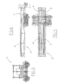
- Figure 1 shows a side view of a sorting apparatus according to the present invention;
- Figure 2 shows a top view of the apparatus of Figure 1;
- Figure 3 shows a front view of an operative component associated with the apparatus of Figure 1;
- Figures 4 and 5 respectively show a side and top view of the operative component of Figure 3;
- Figures 6 and 7 respectively show a side and front view of a construction detail of the apparatus of Figure 1;
- Figure 8 shows a schematic view of the operation of the operative component shown in Figures 3, 4 and 5.
- With particular reference to Figures 1 and 2, the apparatus is globally indicated with the number 1 and comprises
means 2 for supplying the packages to at least astation 3 for manipulating and orienting the packages themselves. - In the illustrated example, the
means 2 for supplying the packages comprise a pair ofconveyor belts station 3. - The presence of a pair of conveyor belts allows to supply the packages on two rows, thereby optimising plant productivity. However, by synchronising the speeds of advance of the conveyor belt, it is also possible to place each package on both belts, in such a way as to supply a single row of packages to the manipulating station.
- The
conveyor belts station 3 and they unload the packages on a subsequent conveyor belt 6 associated with the manipulatingstation 3 and positioned on an ideal extension of theconveyor belts - The manipulating
station 3 originally comprises at least amanipulator head 7 having at least two degrees of freedom of motion. Specifically, in Figure 1 the manipulator head is illustrated in two different operative positions: in a first operative position the head was distinguished with thenumber 7, whilst in a second operative position the head was distinguished with thenumber 77. - In the illustrated embodiment, said
head 7 is movable by translation according to the axes of an orthogonal Cartesian triad. Specifically, thehead 7 translates in a plane that is parallel to an upper surface 6a of the conveyor belt 6, according to two directions X and Y (not shown); moreover, thehead 7 moves along a direction Z (not shown) that is substantially vertical and perpendicular to said plane lying parallel to the upper surface 6a of the belt 6. - The
head 7 is also movable by rotation about a substantially vertical axis, to enable the packages to rotate by predefined angular quantities according to the final configuration to be obtained. - Specifically, the
head 7 is movable by sliding on a guide 7a, transverse relative to the direction of advance of the conveyor belt 6. The guide 7a in turn translates on rails 7b, according to a direction that is substantially parallel to the direction of advance of the conveyor belt 6. - With reference to Figures 6 and 7, the
manipulator head 7 comprises grip means 8 to move the packages, driving them on the surface of the conveyor belt 6. In the illustrated example, said grip means are preferably grippers constituted by a pair ofgripping appendages 8a, 8b, which can vary their relative distance to adapt the gripper to the dimensions of the packages. In particular, a first appendage 8a is integral with the structure of themanipulator head 7, whilst asecond appendage 8b is integral with a rod 9 able to slide within acorresponding cylinder 10. - In the illustrated example, the apparatus 1 is preferably provided with a pair of manipulating
stations 3, positioned one immediately after the other and each fitted with its own conveyor belt. - The apparatus 1 is also provided with a
station 11 for accumulating the packages, said station also being provided with its own conveyor belt, independent of the conveyor belts described above. - In the preferred embodiment, all conveyor belts described are independent and provided with a dedicated motorisation.
- Downstream of the
accumulation station 11, there is astation 12, provided withmeans 13 for thrusting the packages onto a palletiser. - The operation of the invention is as follows:
- The
belts station 3, making the pass on the conveyor belt 6 associated to said station. - With reference to Figure 8, the packages are put in step by means of a pair of photocells facing each other (designated by B4 and B5 in the figure); a pair of sensors (designated by SQ4 and SQ5 in the figure) for counting the RPM of the motors (designated by M4 and M5 in the figure) of each
conveyor belt number 100 indicates the direction of supply of the packages. - Assuming that the package moved by the
belt 4 is ahead of the package moved by thebelt 5, as soon as the package ahead arrives in front of the photocell B4, the sensor SQ4 checks the RPM of the motor M4, in order to increase the counter Z. - Evaluating the value assumed by the counter, the speed decrease to be attributed to the motor M4 in order to slow the advance of the
belt 4 is calculated. Specifically, the velocity of thebelt 4 is obtained by subtracting the velocity of thebelt 5 by a quantity that is proportional to the quantity Z. - When a package positioned too far behind arrives in correspondence with the photocell B5, the sensor SQ5 checks the RPM of the motor M5, in order to decrease Z, in such a way as to increase the velocity of the
belt 5. - If the value of the counter Z becomes too high (i.e. the packages to be put in step are very distant from each other), the motor M4 will stop operating.
- When the counter Z reaches zero, the packages moved by the
belts - If the apparatus has to work with the package travelling on the two belts at the same time, the velocity of the two belts must be mutually synchronised.
- The operation is as follows.
- First of all, a master belt is selected, for instance the
belt 4, and the velocity of the motor M4 is set. - The counter Z is increased by means of the sensor SQ4 and it is simultaneously decreased by means of the sensor SQ5. The absolute value obtained from said algebraic sum allows to synchronise the velocities of advance of the belts.
- Specifically, if the value of Z is positive, then the motor M4 is rotating more rapidly than the motor M5 and therefore the RPM of M5 is increased relative to M4 by a percentage calculated on the basis of the counter Z; if the value is negative, then the motor M5 is rotating more rapidly than the motor M4 and thus the RPM of M5 is decreased relative to M4 by a percentage calculated on the basis of the counter Z.
- When the counter Z reaches a value of zero, the belts are travelling as the same velocity.
- During the movement of the conveyor 6, the packages are followed by the
manipulator head 7 which, if necessary, grips them and orients them according to the final configuration to be obtained. - The invention achieves important advantages.
- First of all, such an apparatus allows to obtain a very high number of final configurations of the packages, since the
manipulator head 7 has one more degree of freedom of motion than the aforementioned prior art. Secondly, the presence of multiple manipulating stations allows to vary the productivity of the apparatus in extremely effective and flexible fashion.
Claims (7)
- An apparatus (1) for arranging and orienting packages, comprising means (2) for supplying the packages to at least a station (3) for their manipulation and orientation, said manipulating station (3) comprising at least a manipulator head (7), at least a belt conveyor (6) associated with the manipulating station (3), the manipulator head (7) being movable by rotating about a substantially vertical axis, for orienting the packages on an upper surface (6a) of the conveyor belt (6) contemporaneusly to the movement of the packages caused by the advancing of said conveyor belt (6), characterised in that the manipulator head (7) is movable by translation according to the axes of an orthogonal Cartesian triad and
said means (2) for supplying the packages comprise a pair of conveyor belts (4,5) movable with variable and independent speeds in order to put the packages in step before their supply to the manipulating station (3), and
each conveyor belt is associated with:at least an actuating motor (M4, M5);at least a photocell (B4, B5) for detecting the presence of a package on a belt;at least a sensor (SQ4, SQ5) cooperating with a correspondent actuating motor (M4, M5) for counting the RPM of said motor, and at least a processor for increasing a counter as a function of the RPM of the motor of a first belt (4) whereon a package positioned ahead is detected;decreasing the velocity of advance of the first belt as a function of the value assumed by the counter;decreasing the counter according to the RPM of the motor of a second conveyor belt (5) whereon a package positioned behind is detected; andincreasing the velocity of advance of the second conveyor belt as a function of the value assumed by the counter. - An apparatus as claimed in claim 1, characterised in that the manipulator head (7) comprises gripping means to displace the packages.
- An apparatus as claimed in claim 2, characterised in that the gripping means are grippers provided with gripping appendages (8a;8b), a first appendage (8a) being integral with the structure of the manipulator head (7) and a second appendage (8b) being integral with a rod (9) which can slide inside a corresponding cylinder (10) obtained in the structure of the head (7).
- An apparatus as claimed in claim 1, characterised in that it further comprises a guide (7A) transverse relative to a direction of advance of the conveyor belt (6), said guide (7a) translating on rails (7b) according to a direction that is substantially parallel to the direction of advance of the conveyor belt (6), said manipulatir head (7) being movable by sliding on said guide (7a).
- An apparatus as claimed 1, characterised in that the upper surface (6a) of the conveyor belt (6) is flat and defines a single substantially horizontal plane.
- An apparatus as claimed in any of the preceeding claims, characterised in that said pair of conveyor belts (4, 5) are positioned externally to the manipulating station (3) and they unload the packages on the belt conveyor (6) associated with the manipulating station (3).
- A method for putting in step packages conveyed by conveyor belts set side by side, comprising the following steps:- detecting the package positioned ahead;- measuring the RPM of an actuating motor (M4) of a first belt (4) whereon the package positioned ahead is located;- increasing a counter as a function of the RPM of the motor of the first belt;- decreasing the velocity of advance of the first belt as a function of the value assumed by the counter;- detecting the package positioned behind;- measuring the RPM of an actuating motor (M5) of a second conveyor belt (5) whereon the package positioned behind is located;- decreasing the counter according to the RPM of the motor of the second belt;increasing the velocity of advance of the second conveyor belt as a function of the value assumed by the counter.
Applications Claiming Priority (3)
| Application Number | Priority Date | Filing Date | Title |
|---|---|---|---|
| ITPR20020062 | 2002-10-31 | ||
| IT000062A ITPR20020062A1 (en) | 2002-10-31 | 2002-10-31 | APPARATUS OF PACKAGING AND PROCEDURE. |
| PCT/IT2003/000452 WO2004039705A1 (en) | 2002-10-31 | 2003-07-23 | Method and apparatus for arranging and orienting packages |
Publications (2)
| Publication Number | Publication Date |
|---|---|
| EP1578680A1 EP1578680A1 (en) | 2005-09-28 |
| EP1578680B1 true EP1578680B1 (en) | 2007-04-04 |
Family
ID=32211410
Family Applications (1)
| Application Number | Title | Priority Date | Filing Date |
|---|---|---|---|
| EP03809834A Expired - Lifetime EP1578680B1 (en) | 2002-10-31 | 2003-07-23 | Method and apparatus for arranging and orienting packages |
Country Status (11)
| Country | Link |
|---|---|
| US (1) | US7422097B2 (en) |
| EP (1) | EP1578680B1 (en) |
| AT (1) | ATE358644T1 (en) |
| AU (1) | AU2003253264A1 (en) |
| BR (1) | BR0315930B1 (en) |
| DE (1) | DE60313039T2 (en) |
| EA (1) | EA007237B1 (en) |
| ES (1) | ES2285260T3 (en) |
| IT (1) | ITPR20020062A1 (en) |
| MX (1) | MXPA05004718A (en) |
| WO (1) | WO2004039705A1 (en) |
Cited By (6)
| Publication number | Priority date | Publication date | Assignee | Title |
|---|---|---|---|---|
| EP2107018A1 (en) | 2008-04-04 | 2009-10-07 | Krones AG | Method and device for compiling and aligning container groups |
| DE102008055471A1 (en) | 2008-04-04 | 2009-10-08 | Krones Ag | Method and device for assembling and aligning container groups |
| DE102008026243A1 (en) | 2008-05-30 | 2009-12-03 | Krones Ag | Drive e.g. direct drive, for endless belt in foodstuffs or semi-luxury products industry, has stator and rotor with rotation axis, which is directly connected with shaft of roller, where drive is designed as electric motor |
| FR2971182A1 (en) * | 2011-02-08 | 2012-08-10 | Promalyon | Gripping device for multi-axis robot utilized for e.g. automatic conveying of box, has jaw moved between retracted and extended positions and controlled by control unit, and connection interface connecting servo motor to control unit |
| EP2749512B1 (en) | 2012-12-28 | 2015-11-25 | Gebo Packaging Solutions Italy SRL | Unit and method for forming a layer of batches of groups of articles |
| WO2017054979A1 (en) | 2015-10-02 | 2017-04-06 | Krones Aktiengesellschaft | Device for transporting articles, and method for arranging articles |
Families Citing this family (10)
| Publication number | Priority date | Publication date | Assignee | Title |
|---|---|---|---|---|
| DE102008020622A1 (en) | 2008-04-24 | 2009-10-29 | Krones Ag | Device and method for re-sorting piece goods compilations |
| WO2010089783A1 (en) * | 2009-02-06 | 2010-08-12 | Sidel S.P.A. Con Socio Unico | Sorting apparatus and method for sorting groups of containers |
| DE102009003845A1 (en) | 2009-04-29 | 2010-11-04 | Krones Ag | Device and method for the defined merging of containers and / or container groups |
| ES2375893B1 (en) * | 2010-07-29 | 2013-02-01 | Computel Informática Y Telefonía, S.L. | SYSTEM FOR THE ANALYSIS AND SALE OF TABLES, BLOCKS, Slabs AND OTHER PRODUCTS OF NATURAL STONE. |
| DE102011076864B4 (en) | 2011-06-01 | 2023-07-27 | Krones Aktiengesellschaft | Device and method for picking up, transporting and delivering containers |
| DE102011080812A1 (en) | 2011-08-11 | 2013-02-14 | Krones Aktiengesellschaft | Method and device for forming layers of articles, piece goods or containers |
| ITPR20120027A1 (en) * | 2012-05-07 | 2013-11-08 | Gea Procomac Spa | METHOD AND FORMATION SYSTEM OF A LAYER OF PACKAGING PACKAGES |
| DE102014223319A1 (en) | 2014-11-14 | 2016-05-19 | Krones Aktiengesellschaft | Method and arrangement for transporting articles, piece goods and / or containers within at least two conveyor sections |
| CN104843472B (en) * | 2015-04-27 | 2017-03-01 | 深圳山源电器股份有限公司 | A kind of automatic screening let-off gear(stand) |
| CN114234760B (en) * | 2021-12-15 | 2024-03-19 | 苏州博众智能机器人有限公司 | Positioning structure |
Citations (1)
| Publication number | Priority date | Publication date | Assignee | Title |
|---|---|---|---|---|
| EP1046598A1 (en) * | 1999-04-20 | 2000-10-25 | Kisters, Inc | Apparatus for making palletizable layers of packaging units |
Family Cites Families (14)
| Publication number | Priority date | Publication date | Assignee | Title |
|---|---|---|---|---|
| US634984A (en) * | 1897-12-31 | 1899-10-17 | Chem Fab Von Max Jasper | Manufacturing durable incandescent bodies. |
| GB1516303A (en) * | 1974-07-19 | 1978-07-05 | Metal Box Co Ltd | Conveyor apparatus |
| GB1510785A (en) * | 1974-07-19 | 1978-05-17 | Metal Box Co Ltd | Conveyor apparatus for handling articles |
| US4016788A (en) * | 1974-07-19 | 1977-04-12 | The Metal Box Company Limited | Conveyor systems |
| FR2396709A1 (en) * | 1977-07-08 | 1979-02-02 | Thibault Jacques | PALLETISING EQUIPMENT |
| US4247025A (en) * | 1979-08-06 | 1981-01-27 | Summit Packaging Systems, Inc. | Aerosol valve having liquid-phase/vapor-phase mixer-homogenizer |
| DE3630791C1 (en) * | 1986-09-10 | 1987-10-22 | Bahlsens Keksfabrik | Method and device for conveying piece goods and for organizing their situation |
| JPH01216788A (en) | 1988-02-23 | 1989-08-30 | Toshiba Corp | Device for confirming molding |
| EP0377399B1 (en) * | 1988-12-31 | 1992-12-02 | System Gmbh | Gripping device |
| US5475449A (en) * | 1993-09-22 | 1995-12-12 | Pyle; Nigel | Safety glass/ear plug combination |
| US5687831A (en) * | 1995-04-25 | 1997-11-18 | Adept Technology, Inc. | Flexible parts feeder |
| DE19752908A1 (en) | 1997-11-28 | 1999-06-02 | Peter Nagler | Process for automated grouping of objects |
| NL1014063C2 (en) * | 2000-01-14 | 2001-07-17 | Food Processing Systems | Device for repositioning products while maintaining forward transport speed. |
| US6540063B1 (en) * | 2000-06-14 | 2003-04-01 | David M. Fallas | Conveyor assembly for providing selectively spaced products |
-
2002
- 2002-10-31 IT IT000062A patent/ITPR20020062A1/en unknown
-
2003
- 2003-07-23 AT AT03809834T patent/ATE358644T1/en not_active IP Right Cessation
- 2003-07-23 EA EA200500689A patent/EA007237B1/en unknown
- 2003-07-23 MX MXPA05004718A patent/MXPA05004718A/en active IP Right Grant
- 2003-07-23 EP EP03809834A patent/EP1578680B1/en not_active Expired - Lifetime
- 2003-07-23 AU AU2003253264A patent/AU2003253264A1/en not_active Abandoned
- 2003-07-23 DE DE60313039T patent/DE60313039T2/en not_active Expired - Lifetime
- 2003-07-23 US US10/533,367 patent/US7422097B2/en not_active Expired - Lifetime
- 2003-07-23 BR BRPI0315930-2A patent/BR0315930B1/en active IP Right Grant
- 2003-07-23 WO PCT/IT2003/000452 patent/WO2004039705A1/en not_active Ceased
- 2003-07-23 ES ES03809834T patent/ES2285260T3/en not_active Expired - Lifetime
Patent Citations (1)
| Publication number | Priority date | Publication date | Assignee | Title |
|---|---|---|---|---|
| EP1046598A1 (en) * | 1999-04-20 | 2000-10-25 | Kisters, Inc | Apparatus for making palletizable layers of packaging units |
Cited By (8)
| Publication number | Priority date | Publication date | Assignee | Title |
|---|---|---|---|---|
| EP2107018A1 (en) | 2008-04-04 | 2009-10-07 | Krones AG | Method and device for compiling and aligning container groups |
| DE102008055471A1 (en) | 2008-04-04 | 2009-10-08 | Krones Ag | Method and device for assembling and aligning container groups |
| DE102008026243A1 (en) | 2008-05-30 | 2009-12-03 | Krones Ag | Drive e.g. direct drive, for endless belt in foodstuffs or semi-luxury products industry, has stator and rotor with rotation axis, which is directly connected with shaft of roller, where drive is designed as electric motor |
| FR2971182A1 (en) * | 2011-02-08 | 2012-08-10 | Promalyon | Gripping device for multi-axis robot utilized for e.g. automatic conveying of box, has jaw moved between retracted and extended positions and controlled by control unit, and connection interface connecting servo motor to control unit |
| EP2749512B1 (en) | 2012-12-28 | 2015-11-25 | Gebo Packaging Solutions Italy SRL | Unit and method for forming a layer of batches of groups of articles |
| WO2017054979A1 (en) | 2015-10-02 | 2017-04-06 | Krones Aktiengesellschaft | Device for transporting articles, and method for arranging articles |
| DE102015116785A1 (en) | 2015-10-02 | 2017-04-06 | Krones Aktiengesellschaft | Device for transporting articles and method for arranging articles |
| DE102015116785B4 (en) * | 2015-10-02 | 2025-06-26 | Krones Aktiengesellschaft | Device for transporting articles and method for arranging articles |
Also Published As
| Publication number | Publication date |
|---|---|
| BR0315930B1 (en) | 2014-06-03 |
| US20060151293A1 (en) | 2006-07-13 |
| AU2003253264A1 (en) | 2004-05-25 |
| WO2004039705A1 (en) | 2004-05-13 |
| ES2285260T3 (en) | 2007-11-16 |
| MXPA05004718A (en) | 2006-02-17 |
| EA200500689A1 (en) | 2006-04-28 |
| DE60313039T2 (en) | 2007-12-13 |
| US7422097B2 (en) | 2008-09-09 |
| EA007237B1 (en) | 2006-08-25 |
| EP1578680A1 (en) | 2005-09-28 |
| BR0315930A (en) | 2005-09-13 |
| ITPR20020062A1 (en) | 2004-05-01 |
| ATE358644T1 (en) | 2007-04-15 |
| DE60313039D1 (en) | 2007-05-16 |
Similar Documents
| Publication | Publication Date | Title |
|---|---|---|
| EP1578680B1 (en) | Method and apparatus for arranging and orienting packages | |
| US7896151B2 (en) | Method and apparatus for combining and aligning packing unit groups | |
| US11034534B2 (en) | Apparatus and method for handling moving piece goods, and a conveying, processing and/or packaging plant with an apparatus for handling moving piece goods | |
| EP2252532B1 (en) | System for processing articles | |
| US11485586B2 (en) | Apparatus and method for handling piece goods moved one after another | |
| US11535458B2 (en) | Apparatus, system and method for orientating articles | |
| EP2723660B1 (en) | Robotic unscrambler and method | |
| CN110431095B (en) | Device for producing batches of products from a plurality of products | |
| CN111051225B (en) | Apparatus and method for orienting a cluster | |
| US11377306B2 (en) | Device for grouping containers | |
| US10207876B2 (en) | Transport device for trays | |
| US4227606A (en) | Apparatus for spacing articles moving in a line | |
| US11053082B2 (en) | Method and apparatus for handling piece goods moved one after the other in at least one row | |
| US20200189776A1 (en) | Handling apparatus and/or packaging apparatus and method used to package article groups in outer packaging | |
| CN114502471A (en) | Item Picking and Handling Equipment | |
| US11932495B2 (en) | Robotic unscrambler | |
| CN114450227A (en) | Packaging equipment | |
| US11299354B2 (en) | Orienting device and a method for orienting an object | |
| CN114007965A (en) | Device and method for handling and/or transporting piece goods moving in at least one row | |
| CA1082636A (en) | Apparatus for spacing articles moving in a line | |
| US20210216947A1 (en) | Production of batches of products for palletizing in layers | |
| CN216836079U (en) | High-speed case marshalling device | |
| US12595139B1 (en) | High-speed array former and methods thereof | |
| WO2018089729A1 (en) | Method and device for stacking products |
Legal Events
| Date | Code | Title | Description |
|---|---|---|---|
| PUAI | Public reference made under article 153(3) epc to a published international application that has entered the european phase |
Free format text: ORIGINAL CODE: 0009012 |
|
| 17P | Request for examination filed |
Effective date: 20050429 |
|
| AK | Designated contracting states |
Kind code of ref document: A1 Designated state(s): AT BE BG CH CY CZ DE DK EE ES FI FR GB GR HU IE IT LI LU MC NL PT RO SE SI SK TR |
|
| AX | Request for extension of the european patent |
Extension state: AL LT LV MK |
|
| DAX | Request for extension of the european patent (deleted) | ||
| GRAP | Despatch of communication of intention to grant a patent |
Free format text: ORIGINAL CODE: EPIDOSNIGR1 |
|
| GRAS | Grant fee paid |
Free format text: ORIGINAL CODE: EPIDOSNIGR3 |
|
| GRAA | (expected) grant |
Free format text: ORIGINAL CODE: 0009210 |
|
| AK | Designated contracting states |
Kind code of ref document: B1 Designated state(s): AT BE BG CH CY CZ DE DK EE ES FI FR GB GR HU IE IT LI LU MC NL PT RO SE SI SK TR |
|
| PG25 | Lapsed in a contracting state [announced via postgrant information from national office to epo] |
Ref country code: CH Free format text: LAPSE BECAUSE OF FAILURE TO SUBMIT A TRANSLATION OF THE DESCRIPTION OR TO PAY THE FEE WITHIN THE PRESCRIBED TIME-LIMIT Effective date: 20070404 Ref country code: FI Free format text: LAPSE BECAUSE OF FAILURE TO SUBMIT A TRANSLATION OF THE DESCRIPTION OR TO PAY THE FEE WITHIN THE PRESCRIBED TIME-LIMIT Effective date: 20070404 Ref country code: SI Free format text: LAPSE BECAUSE OF FAILURE TO SUBMIT A TRANSLATION OF THE DESCRIPTION OR TO PAY THE FEE WITHIN THE PRESCRIBED TIME-LIMIT Effective date: 20070404 Ref country code: LI Free format text: LAPSE BECAUSE OF FAILURE TO SUBMIT A TRANSLATION OF THE DESCRIPTION OR TO PAY THE FEE WITHIN THE PRESCRIBED TIME-LIMIT Effective date: 20070404 |
|
| REG | Reference to a national code |
Ref country code: GB Ref legal event code: FG4D |
|
| REG | Reference to a national code |
Ref country code: CH Ref legal event code: EP |
|
| REF | Corresponds to: |
Ref document number: 60313039 Country of ref document: DE Date of ref document: 20070516 Kind code of ref document: P |
|
| REG | Reference to a national code |
Ref country code: IE Ref legal event code: FG4D |
|
| PG25 | Lapsed in a contracting state [announced via postgrant information from national office to epo] |
Ref country code: SE Free format text: LAPSE BECAUSE OF FAILURE TO SUBMIT A TRANSLATION OF THE DESCRIPTION OR TO PAY THE FEE WITHIN THE PRESCRIBED TIME-LIMIT Effective date: 20070704 |
|
| PG25 | Lapsed in a contracting state [announced via postgrant information from national office to epo] |
Ref country code: PT Free format text: LAPSE BECAUSE OF FAILURE TO SUBMIT A TRANSLATION OF THE DESCRIPTION OR TO PAY THE FEE WITHIN THE PRESCRIBED TIME-LIMIT Effective date: 20070904 |
|
| NLV1 | Nl: lapsed or annulled due to failure to fulfill the requirements of art. 29p and 29m of the patents act | ||
| ET | Fr: translation filed | ||
| REG | Reference to a national code |
Ref country code: CH Ref legal event code: PL |
|
| REG | Reference to a national code |
Ref country code: ES Ref legal event code: FG2A Ref document number: 2285260 Country of ref document: ES Kind code of ref document: T3 |
|
| PG25 | Lapsed in a contracting state [announced via postgrant information from national office to epo] |
Ref country code: AT Free format text: LAPSE BECAUSE OF FAILURE TO SUBMIT A TRANSLATION OF THE DESCRIPTION OR TO PAY THE FEE WITHIN THE PRESCRIBED TIME-LIMIT Effective date: 20070404 |
|
| PG25 | Lapsed in a contracting state [announced via postgrant information from national office to epo] |
Ref country code: BE Free format text: LAPSE BECAUSE OF FAILURE TO SUBMIT A TRANSLATION OF THE DESCRIPTION OR TO PAY THE FEE WITHIN THE PRESCRIBED TIME-LIMIT Effective date: 20070404 |
|
| PG25 | Lapsed in a contracting state [announced via postgrant information from national office to epo] |
Ref country code: CZ Free format text: LAPSE BECAUSE OF FAILURE TO SUBMIT A TRANSLATION OF THE DESCRIPTION OR TO PAY THE FEE WITHIN THE PRESCRIBED TIME-LIMIT Effective date: 20070404 Ref country code: BG Free format text: LAPSE BECAUSE OF FAILURE TO SUBMIT A TRANSLATION OF THE DESCRIPTION OR TO PAY THE FEE WITHIN THE PRESCRIBED TIME-LIMIT Effective date: 20070704 Ref country code: NL Free format text: LAPSE BECAUSE OF FAILURE TO SUBMIT A TRANSLATION OF THE DESCRIPTION OR TO PAY THE FEE WITHIN THE PRESCRIBED TIME-LIMIT Effective date: 20070404 Ref country code: DK Free format text: LAPSE BECAUSE OF FAILURE TO SUBMIT A TRANSLATION OF THE DESCRIPTION OR TO PAY THE FEE WITHIN THE PRESCRIBED TIME-LIMIT Effective date: 20070404 |
|
| PLBE | No opposition filed within time limit |
Free format text: ORIGINAL CODE: 0009261 |
|
| STAA | Information on the status of an ep patent application or granted ep patent |
Free format text: STATUS: NO OPPOSITION FILED WITHIN TIME LIMIT |
|
| PG25 | Lapsed in a contracting state [announced via postgrant information from national office to epo] |
Ref country code: SK Free format text: LAPSE BECAUSE OF FAILURE TO SUBMIT A TRANSLATION OF THE DESCRIPTION OR TO PAY THE FEE WITHIN THE PRESCRIBED TIME-LIMIT Effective date: 20070404 |
|
| 26N | No opposition filed |
Effective date: 20080107 |
|
| PG25 | Lapsed in a contracting state [announced via postgrant information from national office to epo] |
Ref country code: GR Free format text: LAPSE BECAUSE OF FAILURE TO SUBMIT A TRANSLATION OF THE DESCRIPTION OR TO PAY THE FEE WITHIN THE PRESCRIBED TIME-LIMIT Effective date: 20070705 Ref country code: MC Free format text: LAPSE BECAUSE OF NON-PAYMENT OF DUE FEES Effective date: 20070731 |
|
| PG25 | Lapsed in a contracting state [announced via postgrant information from national office to epo] |
Ref country code: RO Free format text: LAPSE BECAUSE OF FAILURE TO SUBMIT A TRANSLATION OF THE DESCRIPTION OR TO PAY THE FEE WITHIN THE PRESCRIBED TIME-LIMIT Effective date: 20070404 |
|
| PG25 | Lapsed in a contracting state [announced via postgrant information from national office to epo] |
Ref country code: IE Free format text: LAPSE BECAUSE OF NON-PAYMENT OF DUE FEES Effective date: 20070723 |
|
| PG25 | Lapsed in a contracting state [announced via postgrant information from national office to epo] |
Ref country code: EE Free format text: LAPSE BECAUSE OF FAILURE TO SUBMIT A TRANSLATION OF THE DESCRIPTION OR TO PAY THE FEE WITHIN THE PRESCRIBED TIME-LIMIT Effective date: 20070404 |
|
| PG25 | Lapsed in a contracting state [announced via postgrant information from national office to epo] |
Ref country code: CY Free format text: LAPSE BECAUSE OF FAILURE TO SUBMIT A TRANSLATION OF THE DESCRIPTION OR TO PAY THE FEE WITHIN THE PRESCRIBED TIME-LIMIT Effective date: 20070404 |
|
| PG25 | Lapsed in a contracting state [announced via postgrant information from national office to epo] |
Ref country code: LU Free format text: LAPSE BECAUSE OF NON-PAYMENT OF DUE FEES Effective date: 20070723 |
|
| PG25 | Lapsed in a contracting state [announced via postgrant information from national office to epo] |
Ref country code: TR Free format text: LAPSE BECAUSE OF FAILURE TO SUBMIT A TRANSLATION OF THE DESCRIPTION OR TO PAY THE FEE WITHIN THE PRESCRIBED TIME-LIMIT Effective date: 20070404 Ref country code: HU Free format text: LAPSE BECAUSE OF FAILURE TO SUBMIT A TRANSLATION OF THE DESCRIPTION OR TO PAY THE FEE WITHIN THE PRESCRIBED TIME-LIMIT Effective date: 20071005 |
|
| REG | Reference to a national code |
Ref country code: FR Ref legal event code: PLFP Year of fee payment: 14 |
|
| REG | Reference to a national code |
Ref country code: FR Ref legal event code: PLFP Year of fee payment: 15 |
|
| REG | Reference to a national code |
Ref country code: FR Ref legal event code: PLFP Year of fee payment: 16 |
|
| PGFP | Annual fee paid to national office [announced via postgrant information from national office to epo] |
Ref country code: IT Payment date: 20220718 Year of fee payment: 20 Ref country code: GB Payment date: 20220719 Year of fee payment: 20 Ref country code: ES Payment date: 20220817 Year of fee payment: 20 Ref country code: DE Payment date: 20220727 Year of fee payment: 20 |
|
| PGFP | Annual fee paid to national office [announced via postgrant information from national office to epo] |
Ref country code: FR Payment date: 20220725 Year of fee payment: 20 |
|
| REG | Reference to a national code |
Ref country code: DE Ref legal event code: R071 Ref document number: 60313039 Country of ref document: DE |
|
| REG | Reference to a national code |
Ref country code: ES Ref legal event code: FD2A Effective date: 20230728 |
|
| REG | Reference to a national code |
Ref country code: GB Ref legal event code: PE20 Expiry date: 20230722 |
|
| PG25 | Lapsed in a contracting state [announced via postgrant information from national office to epo] |
Ref country code: GB Free format text: LAPSE BECAUSE OF EXPIRATION OF PROTECTION Effective date: 20230722 Ref country code: ES Free format text: LAPSE BECAUSE OF EXPIRATION OF PROTECTION Effective date: 20230724 |