EP1584887A1 - Verfahren zur Herstellung eines segmentierten Treibkäfigs für ein unterkalibriges Wuchtgeschoss - Google Patents
Verfahren zur Herstellung eines segmentierten Treibkäfigs für ein unterkalibriges Wuchtgeschoss Download PDFInfo
- Publication number
- EP1584887A1 EP1584887A1 EP05004235A EP05004235A EP1584887A1 EP 1584887 A1 EP1584887 A1 EP 1584887A1 EP 05004235 A EP05004235 A EP 05004235A EP 05004235 A EP05004235 A EP 05004235A EP 1584887 A1 EP1584887 A1 EP 1584887A1
- Authority
- EP
- European Patent Office
- Prior art keywords
- guide part
- base body
- webs
- front support
- ring
- Prior art date
- Legal status (The legal status is an assumption and is not a legal conclusion. Google has not performed a legal analysis and makes no representation as to the accuracy of the status listed.)
- Granted
Links
- 238000004519 manufacturing process Methods 0.000 title claims abstract description 8
- 238000000034 method Methods 0.000 title claims description 11
- 229910052751 metal Inorganic materials 0.000 claims abstract description 5
- 239000002184 metal Substances 0.000 claims abstract description 5
- 229910001092 metal group alloy Inorganic materials 0.000 claims abstract description 5
- 239000004918 carbon fiber reinforced polymer Substances 0.000 claims description 3
- 238000001746 injection moulding Methods 0.000 claims description 2
- 238000002347 injection Methods 0.000 abstract 1
- 239000007924 injection Substances 0.000 abstract 1
- 239000002991 molded plastic Substances 0.000 abstract 1
- 239000003380 propellant Substances 0.000 abstract 1
- 239000004033 plastic Substances 0.000 description 6
- 229920003023 plastic Polymers 0.000 description 6
- 238000010304 firing Methods 0.000 description 2
- 229920000049 Carbon (fiber) Polymers 0.000 description 1
- 229920000299 Nylon 12 Polymers 0.000 description 1
- 229920006099 Vestamid® Polymers 0.000 description 1
- 238000010521 absorption reaction Methods 0.000 description 1
- 239000000853 adhesive Substances 0.000 description 1
- 230000001070 adhesive effect Effects 0.000 description 1
- 230000002411 adverse Effects 0.000 description 1
- 229910045601 alloy Inorganic materials 0.000 description 1
- 239000000956 alloy Substances 0.000 description 1
- 229910052782 aluminium Inorganic materials 0.000 description 1
- XAGFODPZIPBFFR-UHFFFAOYSA-N aluminium Chemical compound [Al] XAGFODPZIPBFFR-UHFFFAOYSA-N 0.000 description 1
- 239000004917 carbon fiber Substances 0.000 description 1
- 230000001419 dependent effect Effects 0.000 description 1
- 238000007373 indentation Methods 0.000 description 1
- 238000003780 insertion Methods 0.000 description 1
- 230000037431 insertion Effects 0.000 description 1
- 238000009434 installation Methods 0.000 description 1
- 239000000463 material Substances 0.000 description 1
- 238000000926 separation method Methods 0.000 description 1
- 229920001169 thermoplastic Polymers 0.000 description 1
- 239000004416 thermosoftening plastic Substances 0.000 description 1
Images


Classifications
-
- F—MECHANICAL ENGINEERING; LIGHTING; HEATING; WEAPONS; BLASTING
- F42—AMMUNITION; BLASTING
- F42B—EXPLOSIVE CHARGES, e.g. FOR BLASTING, FIREWORKS, AMMUNITION
- F42B14/00—Projectiles or missiles characterised by arrangements for guiding or sealing them inside barrels, or for lubricating or cleaning barrels
- F42B14/06—Sub-calibre projectiles having sabots; Sabots therefor
- F42B14/061—Sabots for long rod fin stabilised kinetic energy projectiles, i.e. multisegment sabots attached midway on the projectile
Definitions
- the invention relates to a method for producing a segmented sabot for a preferably large caliber subcaliber mass projectile according to the preamble of Claim 1.
- Such a sabot is known from DE 199 44 376 A1. It consists essentially from a correspondingly segmented basic body of a light metal as well a rear and a front support. While the rear support is formed as a closed flange, the front-side support for Reduce the weight of the sabot more evenly over the circumference of the sabot Sabotage distributed distributed, separated by air flow openings radial Webs of plastic, the outside on a provided with predetermined breaking points, also made of plastic, surrounding ring are connected together. About the kind the attachment of the webs of the front support of the sabot to the body makes the above-mentioned document no further details. Rather, it only becomes mentioned that the ring with the webs are also sprayed onto the body can.
- a sabot for subcaliber projectiles which on the front also one of several evenly over the circumference of the sabot comprises distributed, separated by air flow openings radial webs.
- the radial webs can be connected either in one piece with the base body be made or as separate plastic parts, which are in the circumferential direction extending, dovetail-like grooves of the individual segments of the body be inserted.
- the sliding of the guide parts in the circumferentially extending groove-shaped recesses of the base body has proven to be relatively time-consuming because either only a segment-wise insertion or an indentation from above the individual dovetail-shaped areas of the guide parts in the corresponding groove-shaped recesses of the body is possible.
- the invention is based on the object, a method for producing a segmented Specify sabot of the type mentioned, in which a lower installation costs is required as in known comparable methods, without thereby the accuracy of the corresponding projectile is adversely affected.
- the invention is based on the idea that Front support of the sabot to produce separately and then with the body connect to.
- the support is designed in contrast to DE 33 14 749 A1 in such a way that they are in the direction of the longitudinal axis of the body on the front area can be deferred. This makes it possible, among other things, the front support the sabot in a simple way only after the pre-assembly of the body postpone this and connect with this positive and / or non-positive.
- the inventive method as simple and inexpensive as possible can, it has proved to be advantageous if at least the webs and one of the webs supporting annular foot part is produced as a one-piece guide part, wherein the foot part is formed so that it is either pushed onto the main body or in a central recess of the body can be inserted.
- the front wall portions of the body with slit-shaped recesses to provide, in the connecting the guide member to the body the webs are inserted.
- the one-piece guide part of the front support in addition to the webs and the Foot also includes the outside of the webs adjacent ring.
- predetermined breaking points ring also separately manufacture and then attach to the outer ends of the webs.
- the sabot according to the invention by injection molding made of a suitable plastic, for reasons of sufficient Strength preferably carbon fiber reinforced plastic should be used.
- the guide part but also made of light metal or a light metal alloy.
- the guide member (in the circumferential direction) with respect to the main body on the Foot part of the guide part profilings are arranged, which profiled in accordance, engage in the axial direction extending recesses of the body. So for example, in the case that the foot part of the guide part on the front area the body is to be postponed, this with an inwardly projecting be provided dovetailed or T-shaped profiling, which then into a corresponding dovetailed or T-shaped, in axial Direction of the body extending groove-shaped recess is inserted.
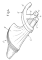
- FIGS. 1-3 1 is an inventive sabot consisting of three segments 2-4 for a subcaliber mass projectile (not shown).
- the sabot 1 comprises a correspondingly segmented and made of aluminum body 5, with a front support 6 and a rear, an air pocket 7 having Support 8.
- the front support 6 is produced separately (FIG. 1) and then axially pushed the main body 5 and with this positive and / or non-positive (e.g. by an adhesive connection) (Fig.2).
- the front support 6 consists of a guide part 9, the six uniformly distributed over the circumference of the sabot 1 arranged webs 10, connected to a foot part 11 and a webs 10 connecting the outside ring 12 are.
- the main body 5 is inside in its front area with an axially extending cylindrical recess 13 and in his laterally adjoining the recess 13 wall portion 14 with one of Number of webs 10 of the guide member 9 corresponding number slot-shaped recesses 15 provided, so that for connecting the base body 5 with the guide member 9 whose foot part 11 axially in the recess 13 and the webs 10 in the slot-shaped Recesses 15 are inserted (Fig.2).
- Fig.2 To secure the guide member 9
- the base body these parts can then be glued together, for example.
- the foot part 11 and the ring 12 comprehensive guide part 9 can be any injection-moldable plastic high strength and low moisture absorption be used.
- the commercially available Vestamid L-CF15 has (Thermoplastic, polyamide 12 reinforced with 15% carbon fibers) proven.
- FIG. 4 shows a further embodiment of the invention is shown. It is for reasons of clarity only a single 2 'designated segment of the sabot reproduced in perspective. With 5 'are the main body and with 8' the rear support designated.
- the foot part 11' on the front portion of the main body 5 ' postponed.
- the invention is not limited to the methods described above.
- the ring provided with predetermined breaking points can also be separated produced and only then molded with the molded-on webs on the body or non-positively connected.
- the ring instead of a carbon fiber reinforced Plastic also consist of a light metal or a light metal alloy, wherein preferably in the region of the separation points of adjacent segments of the base body Predetermined breaking points are provided.
- the guide part instead of plastic also from Alloy or a light metal alloy can be produced.
- the profiling of the guide member for example, a dovetail-shaped Have shape.
- the slot-shaped Recesses not necessarily a radial course with respect to the projectile axis exhibit. Rather, both in terms of angle and in terms the position of the slot-shaped recesses largely arbitrary deviations in be authorized to the projectile axis.
Landscapes
- Engineering & Computer Science (AREA)
- General Engineering & Computer Science (AREA)
- Aiming, Guidance, Guns With A Light Source, Armor, Camouflage, And Targets (AREA)
- Investigating Strength Of Materials By Application Of Mechanical Stress (AREA)
- Toys (AREA)
- Aerodynamic Tests, Hydrodynamic Tests, Wind Tunnels, And Water Tanks (AREA)
Abstract
Description
- 1
- Treibkäfig
- 2, 2', 3, 4
- Segmente
- 5,5'
- Grundkörper
- 6
- (vordere) Abstützung
- 7
- Lufttasche
- 8,8'
- hintere Abstützung
- 9,9'
- Führungsteile
- 10,10'
- Stege
- 11,11'
- Fußteile
- 12,12'
- Ringe
- 13
- Eindrehung
- 14
- Wandbereich
- 15
- schlitzförmige Ausnehmung
- 16-18
- Trennebenen
- 19
- Profilierung
- 20
- nutenförmige Ausnehmung
Claims (8)
- Verfahren zur Herstellung eines segmentierten Treibkäfigs (1) für ein unterkalibriges Wuchtgeschoss, der einen entsprechend segmentierten Grundkörper (5; 5') und eine vordere an dem Grundkörper (5; 5') befestigte Abstützung (6) aufweist, die gleichmäßig über den Umfang des Treibkäfigs (1) verteilt angeordnete Stege (10; 10') umfaßt, welche außenseitig über einen umlaufenden Ring (12; 12') miteinander verbunden sind, dadurch gekennzeichnet, dass die Stege (10; 10') der vorderen Abstützung (6) und ein die Stege (10; 10') tragendes ringförmiges Fußteil (11; 11') als separates einteiliges Führungsteil (9; 9') hergestellt wird, und dass das Fußteil (11') des Führungsteiles (9') in axialer Richtung auf den Grundkörper (5') aufgeschoben oder dass das Fußteil (11) des Führungsteiles (9) in eine zylinderförmige zentrale Eindrehung (13) des Grundkörpers (5) eingeschoben wird, wobei die Stege (10) in entsprechenden schlitzförmigen Ausnehmungen (15) des vorderen Wandbereiches (14) des Grundkörpers (5) eingeführt werden.
- Verfahren nach Anspruch 1, dadurch gekennzeichnet, dass das separate einteilige Führungsteil (9; 9') auch den außenseitig an die Stege (10; 10') angrenzenden Ring (12; 12') umfaßt.
- Verfahren nach Anspruch 1 oder 2, dadurch gekennzeichnet, dass das Führungsteil (9; 9') aus kohlefaserverstärktem Kunststoff besteht und durch Spritzgießen hergestellt wird.
- Verfahren nach Anspruch 1 oder 2, dadurch gekennzeichnet, dass das Führungsteil (9; 9') aus Leichtmetall oder einer Leichtmetall-Legierung hergestellt wird.
- Verfahren nach einem der Ansprüche 1 bis 4, dadurch gekennzeichnet, dass das Fußteil (11; 11') des Führungsteiles (9; 9') und der sich an die Stege (10; 10') des Führungsteiles (9; 9') außenseitig anschließende Ring (12; 12') mit Sollbruchstellen versehen werden, die in der durch benachbarte Segmente (2-4; 2')) des Grundkörpers (5; 5') definierten Trennebenen (16-18) liegen.
- Verfahren nach einem der Ansprüche 1 bis 5, dadurch gekennzeichnet, dass das Führungsteil (9; 9') der vorderen Abstützung auf seiner dem Grundkörper (5; 5') zugewandten Seite mit mindestens einer Profilierung (19) versehen wird, welche zur Verbindung des Grundkörpers (5; 5') mit dem Führungsteil (9; 9') in eine entsprechende, sich in axialer Richtung des Grundkörpers (5; 5') erstreckende nutenförmige Ausnehmung (20) des Grundkörpers (5; 5') eingeschoben wird.
- Verfahren nach Anspruch 6, dadurch gekennzeichnet, dass die Profilierung (19) des Führungsteiles (9; 9') schwalbenschwanzförmig oder T-förmig ausgebildet wird.
- Verfahren nach Anspruch 1, dadurch gekennzeichnet, dass der Ring (12; 12') separat hergestellt und mit dem aus Stegen (10; 10') und Fußteil (11; 11') bestehenden Führungsteil (9; 9') form- und/oder kraftschlüssig verbunden wird.
Applications Claiming Priority (2)
| Application Number | Priority Date | Filing Date | Title |
|---|---|---|---|
| DE102004017674A DE102004017674A1 (de) | 2004-04-10 | 2004-04-10 | Verfahren zur Herstellung eines segmentierten Treibkäfigs für ein unterkalibriges Wuchtgeschoss |
| DE102004017674 | 2004-04-10 |
Publications (2)
| Publication Number | Publication Date |
|---|---|
| EP1584887A1 true EP1584887A1 (de) | 2005-10-12 |
| EP1584887B1 EP1584887B1 (de) | 2009-02-18 |
Family
ID=34895559
Family Applications (1)
| Application Number | Title | Priority Date | Filing Date |
|---|---|---|---|
| EP05004235A Expired - Lifetime EP1584887B1 (de) | 2004-04-10 | 2005-02-26 | Verfahren zur Herstellung eines segmentierten Treibkäfigs für ein unterkalibriges Wuchtgeschoss |
Country Status (4)
| Country | Link |
|---|---|
| EP (1) | EP1584887B1 (de) |
| AT (1) | ATE423301T1 (de) |
| DE (2) | DE102004017674A1 (de) |
| ES (1) | ES2320231T3 (de) |
Cited By (1)
| Publication number | Priority date | Publication date | Assignee | Title |
|---|---|---|---|---|
| WO2021052755A1 (de) * | 2019-09-18 | 2021-03-25 | Rheinmetall Waffe Munition Gmbh | Treibkäfig vom push-pull-typ mit von einander getrennten teilen für die push- und pull-funktion |
Families Citing this family (2)
| Publication number | Priority date | Publication date | Assignee | Title |
|---|---|---|---|---|
| DE102009049440A1 (de) | 2009-10-14 | 2011-07-07 | Nitrochemie Aschau GmbH, 84544 | Treibspiegel |
| DE102022118022A1 (de) | 2022-07-19 | 2024-01-25 | Rheinmetall Waffe Munition Gmbh | Treibkäfig |
Citations (3)
| Publication number | Priority date | Publication date | Assignee | Title |
|---|---|---|---|---|
| DE3314749A1 (de) | 1983-04-23 | 1984-10-25 | L'Etat Français représenté par le Délégué Général pour l'Armement, Paris | Segmentierter treibkaefig |
| US5289777A (en) * | 1992-02-28 | 1994-03-01 | Rheinmetall Gmbh | Subcaliber kinetic energy projectile |
| DE19944376A1 (de) | 1999-09-16 | 2001-03-22 | Rheinmetall W & M Gmbh | Segmentierter Treibkäfig |
-
2004
- 2004-04-10 DE DE102004017674A patent/DE102004017674A1/de not_active Withdrawn
-
2005
- 2005-02-26 ES ES05004235T patent/ES2320231T3/es not_active Expired - Lifetime
- 2005-02-26 EP EP05004235A patent/EP1584887B1/de not_active Expired - Lifetime
- 2005-02-26 AT AT05004235T patent/ATE423301T1/de not_active IP Right Cessation
- 2005-02-26 DE DE502005006631T patent/DE502005006631D1/de not_active Expired - Lifetime
Patent Citations (4)
| Publication number | Priority date | Publication date | Assignee | Title |
|---|---|---|---|---|
| DE3314749A1 (de) | 1983-04-23 | 1984-10-25 | L'Etat Français représenté par le Délégué Général pour l'Armement, Paris | Segmentierter treibkaefig |
| US4608927A (en) * | 1983-04-23 | 1986-09-02 | Rudolf Romer | Segmented sabot |
| US5289777A (en) * | 1992-02-28 | 1994-03-01 | Rheinmetall Gmbh | Subcaliber kinetic energy projectile |
| DE19944376A1 (de) | 1999-09-16 | 2001-03-22 | Rheinmetall W & M Gmbh | Segmentierter Treibkäfig |
Cited By (2)
| Publication number | Priority date | Publication date | Assignee | Title |
|---|---|---|---|---|
| WO2021052755A1 (de) * | 2019-09-18 | 2021-03-25 | Rheinmetall Waffe Munition Gmbh | Treibkäfig vom push-pull-typ mit von einander getrennten teilen für die push- und pull-funktion |
| US11754381B2 (en) | 2019-09-18 | 2023-09-12 | Rheinmetall Waffe Munition Gmbh | Sabot of the push-pull type having mutually separate parts for the push and pull function |
Also Published As
| Publication number | Publication date |
|---|---|
| DE102004017674A1 (de) | 2005-10-27 |
| EP1584887B1 (de) | 2009-02-18 |
| DE502005006631D1 (de) | 2009-04-02 |
| ATE423301T1 (de) | 2009-03-15 |
| ES2320231T3 (es) | 2009-05-20 |
Similar Documents
| Publication | Publication Date | Title |
|---|---|---|
| EP1085289B1 (de) | Hülsenboden für grosskalibrige Munition | |
| EP0853228B1 (de) | Geschoss und Verfahren zu dessen Herstellung | |
| DE2537116A1 (de) | Geschoss- oder fuehrungsring fuer ein unterkalibriges geschoss | |
| EP2179246A1 (de) | Verfahren zur herstellung eines geschosses sowie geschoss | |
| DE102009006858A1 (de) | Wälzlagerkäfig | |
| DE102011089243B4 (de) | Magnetrad | |
| EP1789697A1 (de) | Elastomerlager | |
| DE102007037700A1 (de) | Treib- oder Führungskäfig und Verfahren zur Befestigung derartiger Käfige | |
| DE19500975B4 (de) | Dämpfungslager, insbesondere für den Einbau einer zu einem Scheibenwischermechanismus gehörenden Welle | |
| DE8531659U1 (de) | Vorrichtung zur Befestigung von Lagern | |
| DE2602002A1 (de) | Sicherungs- und/oder distanzring | |
| EP1584887B1 (de) | Verfahren zur Herstellung eines segmentierten Treibkäfigs für ein unterkalibriges Wuchtgeschoss | |
| EP0288721A1 (de) | Ausbildung einer Sollbruchstelle am Heckteil eines Treibspiegels für ein Treibspiegelgeschoss | |
| CH696601A5 (de) | Geschoss und Führungsring für ein Geschoss. | |
| EP0594694B1 (de) | Unterkalibriges geschoss mit treibspiegel | |
| EP0989381B1 (de) | Unterkalibergeschoss | |
| EP3317607B1 (de) | Aus einem gezogenen waffenrohr verschiessbares, flügelstabilisiertes unterkalibergeschoss und verfahren zu seiner herstellung | |
| DE69115167T2 (de) | Vorrichtung zum Sperren der Drehbewegung zwischen Pfeilgeschoss und Treibkäfig. | |
| DE102008029397A1 (de) | Treibkäfiggeschoss | |
| DE19910308B4 (de) | Hydraulisch dämpfendes Gummilager mit Axialanschlägen sowie ein Verfahren zur Herstellung eines solchen hydraulisch dämpfenden Gummilagers mit integrierten Axialanschlägen | |
| DE69305018T2 (de) | Dichtungsband für Pfeilgeschoss | |
| DE102014002093A1 (de) | Dichtring, Lenksäulenanordnung und Kraftfahrzeug | |
| DE69802177T2 (de) | Treibladungshülse für ein jagdgewehr und kartusche, die eine solche hülse hat | |
| DE102004017675A1 (de) | Verfahren zur Herstellung eines segmentierten Treibkäfigs für ein unterkalibriges Wuchtgeschoss | |
| WO2009156031A1 (de) | Treibkäfiggeschoss |
Legal Events
| Date | Code | Title | Description |
|---|---|---|---|
| PUAI | Public reference made under article 153(3) epc to a published international application that has entered the european phase |
Free format text: ORIGINAL CODE: 0009012 |
|
| 17P | Request for examination filed |
Effective date: 20050616 |
|
| AK | Designated contracting states |
Kind code of ref document: A1 Designated state(s): AT BE BG CH CY CZ DE DK EE ES FI FR GB GR HU IE IS IT LI LT LU MC NL PL PT RO SE SI SK TR |
|
| AX | Request for extension of the european patent |
Extension state: AL BA HR LV MK YU |
|
| AKX | Designation fees paid |
Designated state(s): AT BE BG CH CY CZ DE DK EE ES FI FR GB GR HU IE IS IT LI LT LU MC NL PL PT RO SE SI SK TR |
|
| RAP1 | Party data changed (applicant data changed or rights of an application transferred) |
Owner name: RHEINMETALL WAFFE MUNITION GMBH |
|
| GRAP | Despatch of communication of intention to grant a patent |
Free format text: ORIGINAL CODE: EPIDOSNIGR1 |
|
| GRAP | Despatch of communication of intention to grant a patent |
Free format text: ORIGINAL CODE: EPIDOSNIGR1 |
|
| GRAS | Grant fee paid |
Free format text: ORIGINAL CODE: EPIDOSNIGR3 |
|
| GRAA | (expected) grant |
Free format text: ORIGINAL CODE: 0009210 |
|
| AK | Designated contracting states |
Kind code of ref document: B1 Designated state(s): AT BE BG CH CY CZ DE DK EE ES FI FR GB GR HU IE IS IT LI LT LU MC NL PL PT RO SE SI SK TR |
|
| REG | Reference to a national code |
Ref country code: GB Ref legal event code: FG4D Free format text: NOT ENGLISH |
|
| REG | Reference to a national code |
Ref country code: CH Ref legal event code: EP |
|
| REG | Reference to a national code |
Ref country code: IE Ref legal event code: FG4D Free format text: LANGUAGE OF EP DOCUMENT: GERMAN |
|
| REF | Corresponds to: |
Ref document number: 502005006631 Country of ref document: DE Date of ref document: 20090402 Kind code of ref document: P |
|
| REG | Reference to a national code |
Ref country code: ES Ref legal event code: FG2A Ref document number: 2320231 Country of ref document: ES Kind code of ref document: T3 |
|
| PG25 | Lapsed in a contracting state [announced via postgrant information from national office to epo] |
Ref country code: FI Free format text: LAPSE BECAUSE OF FAILURE TO SUBMIT A TRANSLATION OF THE DESCRIPTION OR TO PAY THE FEE WITHIN THE PRESCRIBED TIME-LIMIT Effective date: 20090218 Ref country code: SI Free format text: LAPSE BECAUSE OF FAILURE TO SUBMIT A TRANSLATION OF THE DESCRIPTION OR TO PAY THE FEE WITHIN THE PRESCRIBED TIME-LIMIT Effective date: 20090218 Ref country code: NL Free format text: LAPSE BECAUSE OF FAILURE TO SUBMIT A TRANSLATION OF THE DESCRIPTION OR TO PAY THE FEE WITHIN THE PRESCRIBED TIME-LIMIT Effective date: 20090218 Ref country code: LT Free format text: LAPSE BECAUSE OF FAILURE TO SUBMIT A TRANSLATION OF THE DESCRIPTION OR TO PAY THE FEE WITHIN THE PRESCRIBED TIME-LIMIT Effective date: 20090218 |
|
| NLV1 | Nl: lapsed or annulled due to failure to fulfill the requirements of art. 29p and 29m of the patents act | ||
| BERE | Be: lapsed |
Owner name: RHEINMETALL WAFFE MUNITION G.M.B.H. Effective date: 20090228 |
|
| PG25 | Lapsed in a contracting state [announced via postgrant information from national office to epo] |
Ref country code: IS Free format text: LAPSE BECAUSE OF FAILURE TO SUBMIT A TRANSLATION OF THE DESCRIPTION OR TO PAY THE FEE WITHIN THE PRESCRIBED TIME-LIMIT Effective date: 20090618 Ref country code: PL Free format text: LAPSE BECAUSE OF FAILURE TO SUBMIT A TRANSLATION OF THE DESCRIPTION OR TO PAY THE FEE WITHIN THE PRESCRIBED TIME-LIMIT Effective date: 20090218 Ref country code: SE Free format text: LAPSE BECAUSE OF FAILURE TO SUBMIT A TRANSLATION OF THE DESCRIPTION OR TO PAY THE FEE WITHIN THE PRESCRIBED TIME-LIMIT Effective date: 20090518 |
|
| REG | Reference to a national code |
Ref country code: IE Ref legal event code: FD4D |
|
| PG25 | Lapsed in a contracting state [announced via postgrant information from national office to epo] |
Ref country code: MC Free format text: LAPSE BECAUSE OF NON-PAYMENT OF DUE FEES Effective date: 20090228 |
|
| REG | Reference to a national code |
Ref country code: CH Ref legal event code: PL |
|
| PG25 | Lapsed in a contracting state [announced via postgrant information from national office to epo] |
Ref country code: CH Free format text: LAPSE BECAUSE OF NON-PAYMENT OF DUE FEES Effective date: 20090228 Ref country code: CZ Free format text: LAPSE BECAUSE OF FAILURE TO SUBMIT A TRANSLATION OF THE DESCRIPTION OR TO PAY THE FEE WITHIN THE PRESCRIBED TIME-LIMIT Effective date: 20090218 Ref country code: LI Free format text: LAPSE BECAUSE OF NON-PAYMENT OF DUE FEES Effective date: 20090228 Ref country code: PT Free format text: LAPSE BECAUSE OF FAILURE TO SUBMIT A TRANSLATION OF THE DESCRIPTION OR TO PAY THE FEE WITHIN THE PRESCRIBED TIME-LIMIT Effective date: 20090727 Ref country code: IE Free format text: LAPSE BECAUSE OF FAILURE TO SUBMIT A TRANSLATION OF THE DESCRIPTION OR TO PAY THE FEE WITHIN THE PRESCRIBED TIME-LIMIT Effective date: 20090218 Ref country code: DK Free format text: LAPSE BECAUSE OF FAILURE TO SUBMIT A TRANSLATION OF THE DESCRIPTION OR TO PAY THE FEE WITHIN THE PRESCRIBED TIME-LIMIT Effective date: 20090218 Ref country code: EE Free format text: LAPSE BECAUSE OF FAILURE TO SUBMIT A TRANSLATION OF THE DESCRIPTION OR TO PAY THE FEE WITHIN THE PRESCRIBED TIME-LIMIT Effective date: 20090218 |
|
| PG25 | Lapsed in a contracting state [announced via postgrant information from national office to epo] |
Ref country code: RO Free format text: LAPSE BECAUSE OF FAILURE TO SUBMIT A TRANSLATION OF THE DESCRIPTION OR TO PAY THE FEE WITHIN THE PRESCRIBED TIME-LIMIT Effective date: 20090218 Ref country code: SK Free format text: LAPSE BECAUSE OF FAILURE TO SUBMIT A TRANSLATION OF THE DESCRIPTION OR TO PAY THE FEE WITHIN THE PRESCRIBED TIME-LIMIT Effective date: 20090218 |
|
| PLBE | No opposition filed within time limit |
Free format text: ORIGINAL CODE: 0009261 |
|
| STAA | Information on the status of an ep patent application or granted ep patent |
Free format text: STATUS: NO OPPOSITION FILED WITHIN TIME LIMIT |
|
| 26N | No opposition filed |
Effective date: 20091119 |
|
| PG25 | Lapsed in a contracting state [announced via postgrant information from national office to epo] |
Ref country code: BG Free format text: LAPSE BECAUSE OF FAILURE TO SUBMIT A TRANSLATION OF THE DESCRIPTION OR TO PAY THE FEE WITHIN THE PRESCRIBED TIME-LIMIT Effective date: 20090518 |
|
| PG25 | Lapsed in a contracting state [announced via postgrant information from national office to epo] |
Ref country code: BE Free format text: LAPSE BECAUSE OF NON-PAYMENT OF DUE FEES Effective date: 20090228 |
|
| PG25 | Lapsed in a contracting state [announced via postgrant information from national office to epo] |
Ref country code: AT Free format text: LAPSE BECAUSE OF NON-PAYMENT OF DUE FEES Effective date: 20090226 |
|
| PG25 | Lapsed in a contracting state [announced via postgrant information from national office to epo] |
Ref country code: GR Free format text: LAPSE BECAUSE OF FAILURE TO SUBMIT A TRANSLATION OF THE DESCRIPTION OR TO PAY THE FEE WITHIN THE PRESCRIBED TIME-LIMIT Effective date: 20090519 |
|
| PG25 | Lapsed in a contracting state [announced via postgrant information from national office to epo] |
Ref country code: IT Free format text: LAPSE BECAUSE OF FAILURE TO SUBMIT A TRANSLATION OF THE DESCRIPTION OR TO PAY THE FEE WITHIN THE PRESCRIBED TIME-LIMIT Effective date: 20090218 |
|
| PG25 | Lapsed in a contracting state [announced via postgrant information from national office to epo] |
Ref country code: LU Free format text: LAPSE BECAUSE OF NON-PAYMENT OF DUE FEES Effective date: 20090226 |
|
| PG25 | Lapsed in a contracting state [announced via postgrant information from national office to epo] |
Ref country code: HU Free format text: LAPSE BECAUSE OF FAILURE TO SUBMIT A TRANSLATION OF THE DESCRIPTION OR TO PAY THE FEE WITHIN THE PRESCRIBED TIME-LIMIT Effective date: 20090819 |
|
| PG25 | Lapsed in a contracting state [announced via postgrant information from national office to epo] |
Ref country code: CY Free format text: LAPSE BECAUSE OF FAILURE TO SUBMIT A TRANSLATION OF THE DESCRIPTION OR TO PAY THE FEE WITHIN THE PRESCRIBED TIME-LIMIT Effective date: 20090218 |
|
| REG | Reference to a national code |
Ref country code: FR Ref legal event code: PLFP Year of fee payment: 11 |
|
| PGFP | Annual fee paid to national office [announced via postgrant information from national office to epo] |
Ref country code: DE Payment date: 20150219 Year of fee payment: 11 Ref country code: ES Payment date: 20150217 Year of fee payment: 11 |
|
| PGFP | Annual fee paid to national office [announced via postgrant information from national office to epo] |
Ref country code: FR Payment date: 20150219 Year of fee payment: 11 Ref country code: TR Payment date: 20150128 Year of fee payment: 11 Ref country code: GB Payment date: 20150218 Year of fee payment: 11 |
|
| REG | Reference to a national code |
Ref country code: DE Ref legal event code: R119 Ref document number: 502005006631 Country of ref document: DE |
|
| GBPC | Gb: european patent ceased through non-payment of renewal fee |
Effective date: 20160226 |
|
| REG | Reference to a national code |
Ref country code: FR Ref legal event code: ST Effective date: 20161028 |
|
| PG25 | Lapsed in a contracting state [announced via postgrant information from national office to epo] |
Ref country code: GB Free format text: LAPSE BECAUSE OF NON-PAYMENT OF DUE FEES Effective date: 20160226 Ref country code: DE Free format text: LAPSE BECAUSE OF NON-PAYMENT OF DUE FEES Effective date: 20160901 Ref country code: FR Free format text: LAPSE BECAUSE OF NON-PAYMENT OF DUE FEES Effective date: 20160229 |
|
| PG25 | Lapsed in a contracting state [announced via postgrant information from national office to epo] |
Ref country code: ES Free format text: LAPSE BECAUSE OF NON-PAYMENT OF DUE FEES Effective date: 20160227 |
|
| PG25 | Lapsed in a contracting state [announced via postgrant information from national office to epo] |
Ref country code: TR Free format text: LAPSE BECAUSE OF NON-PAYMENT OF DUE FEES Effective date: 20160226 |