EP1586895A1 - Automated analyser for determining nitrogen content of organic compounds - Google Patents
Automated analyser for determining nitrogen content of organic compounds Download PDFInfo
- Publication number
- EP1586895A1 EP1586895A1 EP05103013A EP05103013A EP1586895A1 EP 1586895 A1 EP1586895 A1 EP 1586895A1 EP 05103013 A EP05103013 A EP 05103013A EP 05103013 A EP05103013 A EP 05103013A EP 1586895 A1 EP1586895 A1 EP 1586895A1
- Authority
- EP
- European Patent Office
- Prior art keywords
- analyser
- combustion
- stage
- nitrogen
- washer
- Prior art date
- Legal status (The legal status is an assumption and is not a legal conclusion. Google has not performed a legal analysis and makes no representation as to the accuracy of the status listed.)
- Granted
Links
Images


Classifications
-
- G—PHYSICS
- G01—MEASURING; TESTING
- G01N—INVESTIGATING OR ANALYSING MATERIALS BY DETERMINING THEIR CHEMICAL OR PHYSICAL PROPERTIES
- G01N31/00—Investigating or analysing non-biological materials by the use of the chemical methods specified in the subgroup; Apparatus specially adapted for such methods
- G01N31/005—Investigating or analysing non-biological materials by the use of the chemical methods specified in the subgroup; Apparatus specially adapted for such methods investigating the presence of an element by oxidation
-
- Y—GENERAL TAGGING OF NEW TECHNOLOGICAL DEVELOPMENTS; GENERAL TAGGING OF CROSS-SECTIONAL TECHNOLOGIES SPANNING OVER SEVERAL SECTIONS OF THE IPC; TECHNICAL SUBJECTS COVERED BY FORMER USPC CROSS-REFERENCE ART COLLECTIONS [XRACs] AND DIGESTS
- Y10—TECHNICAL SUBJECTS COVERED BY FORMER USPC
- Y10T—TECHNICAL SUBJECTS COVERED BY FORMER US CLASSIFICATION
- Y10T436/00—Chemistry: analytical and immunological testing
- Y10T436/17—Nitrogen containing
Definitions
- the present invention relates to an automated analyser, by way of combustion, for determining nitrogen contained in organic compounds present in foods, animal feeds, polymers, fuels etc.
- This method presents a number of operative drawbacks related to the use of sulfuric acid and pollutant catalysts, with the consequent problems of disposing of toxic residues, especially in cases where the aforesaid analysis must be conducted daily on a large number of samples.
- the other method for determining nitrogen devised by Dumas is based on the technique of combustion or oxidation of the nitrogen contained in the organic compound using oxygen to form the various nitrogen oxides, which are subsequently reduced to nitrogen.
- This method is used in the food industry as it is rapid, gives accurate measurement and is also more easily automated.
- Heterogeneous phase combustion in the presence of a solid phase catalyst has the advantage of being able to accelerate combustion using a smaller amount of combustion support. Indeed, in this type of combustion 0.3 g of organic substance can be burnt using 400 ml of oxygen in 30 seconds rather than the 8 litres in over 1 minute used in homogeneous combustion.
- the sample to be analysed is dropped into the heterogeneous combustion reactor in the presence of oxygen.
- the temperature of the oxidation reactor passes from 900 to 1800°C as a consequence of oxygen intake, and the carbon and the hydrogen contained in the organic substance oxidise to carbon dioxide and water.
- the nitrogen is oxidised to N X O Y .
- the gaseous mixture containing carbon dioxide, water and N X O Y is conveyed to the reduction reactor where the aforesaid nitrogen oxides are reduced to nitrogen.
- the gases leaving the reduction reactor are conveyed to the carbon dioxide and water traps by the carrier gas helium.
- the gas leaving the water trap consisting mainly of nitrogen, is fed to the analyser itself which consists of a gas chromatography column and a thermal conductivity detector (TCD or HWD - hot wire detector).
- the detector is then connected to a logic unit for data processing.
- the carbon dioxide traps generally of zeolite, must be replaced frequently to be regenerated, as they become saturated with carbon dioxide in the long term.
- the present invention provides an automatic analyser, by way of combustion, for the determination of nitrogen in organic compounds, in particular proteins present in foods, animal feeds, polymers, fuel etc., comprising:
- a further aspect of the present invention is the aforesaid analyser, further characterised in that the catalytic combustion reactor is in three stages, of which the first stage is a combustion chamber and a collection zone for the ashes which can be easily removed by the use of a retractable quartz insert; the second stage is a catalytic bed for high temperature combustion of organic vapour; the third stage is a catalytic bed suited to oxidation at lower temperatures, enabling complete combustion of possible traces which have only partially combusted.
- a further aspect of the present invention is one of the aforesaid analysers, further characterised in that:
- a further aspect of the present invention is one of the aforesaid nitrogen analysers, characterised in that the water absorber comprises:
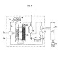
- Figure 1 shows a flow diagram of a preferred embodiment of the nitrogen analyser of the present invention.
- A indicates the gas lines through which helium and oxygen pass upstream of the heterogeneous combustion reactor, while CO 2 , N 2 , water and helium, i.e. the carrier gas, pass downstream of the reduction reactor, only nitrogen and helium passing upstream of the detector.
- B indicates an automatic sampler preferably of 120 positions, consisting of three superposed carousels each comprising 40 positions.
- the sampler is operated by a pneumatic device, which while allowing a sample to fall into the combustion reactor, simultaneously loads the next sample onto a piston-operated slide in the interior of the sampler. Oxygen and helium are also fed into the system via the sampler.
- the heterogeneous combustion reactor is indicated by C, its first stage consisting of a combustion chamber and ash accumulation zone being indicated by C1, and the extractable quartz tube contained in C1 being indicated by C1T.
- the second stage containing a suitable catalytic bed in which the fast oxidation reaction at high temperature takes place is indicated by C2.
- the third stage i.e. that of the slower oxidation reaction, is indicated by C3.
- the catalysts used for the catalytic beds of the first stage and second stage are generally those which are already known and habitually used in fast and slow heterogeneous gas phase oxidation reactions respectively.
- both stages use mixed oxide spinels (oxygen pump) preferably based on Cr/Co for the first stage and preferably based on Cr/Cu for the second stage, both supported on identical supports preferably consisting of alumina but of different surface area, preferably about 6 m 2 /g for the first stage and about 50 m 2 /g for the second stage.
- mixed oxide spinels oxygen pump
- the reduction reactor is indicated by the letter D, D1 indicating the first stage in which NO x is reduced to nitrogen, this stage being conducted in the presence of metallic copper of high surface area (about 0.4 m 2 /g) which enables both the excess oxygen and impurities consisting of S or halogens to be retained, the second stage D2 consisting of a catalytic bed of copper oxide being used for oxidising traces of CO to CO 2 .
- the water absorber is indicated by the letter E, as aforestated, and comprises a moisture exchanger towards the outside, consisting of a tube lapped in counterflow by dry gases conveyed from all the exit emissions from the instrument.
- the water adsorbing device uses moisture exchangers of the ME® series manufactured by Permapure, these being NAFION® membrane tubes.
- the microfilter of a substance capable of adsorbing any traces of unevaporated water and positioned at the exit of the water adsorber, preferably consists of magnesium perchlorate.
- F indicates the CO 2 adsorber device, which will be examined in detail in the course of the present description
- G indicates the detector, which is preferably an absolute electro-conductivity detector, which therefore does not require a flow of reference gas, but is based on the energy developed by a filament maintained at constant temperature by being lapped by a gas of constant flow rate.
- H indicates the logic unit for data processing.
- Said preferred embodiment also comprises a device for verifying the stability of the primary flow, it being indicated by I in Figure 1 and consisting of a flow sensor and a metering valve for controlling any pressure increases within the line A situated upstream of the combustion reactor while metering oxygen during the actual combustion stage.
- the same preferred embodiment also comprises a device for verifying the stability of the secondary flow, it being situated downstream of the CO 2 absorber and indicated by L in Figure 1.
- This device also consists of a flow sensor and a metering valve for controlling any pressure fall within the line A caused by the elimination of excess oxygen, carbon dioxide and finally water, in order to stabilise the detector G.
- the analyser of the present invention comprises both the device I for verifying the stability of the primary flow and the device L for verifying the stability of the secondary flow.
- FIG. 1 The preferred embodiment shown in Figure 1 also shows that a sample weighing system M is connected to the logic unit H for data processing.
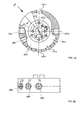
- Figure 2 shows a preferred embodiment of the CO 2 absorption device of the nitrogen analyser of the present invention, where F2 indicates the carousel consisting of a plurality of absorber elements 1008 containing an adsorbent material, and F3 indicates the degassing furnace.
- the elements 1008 are U-shaped glass tubes.
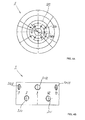
- the distributor valve indicated by F1 in Figure 2 comprises, as can be seen from Figure 3, a shaft 4, an upper body 1 and a lower body 2 both pivoted on the shaft 4.
- a compression and adjustment spring 11, a washer 6, an adjustment nut 12, a backing nut 12A and an adapting washer 5, interposed between the adjustment nut 12 and the compression spring 11, are also mounted on the shaft 4.
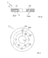
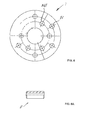
- the gasket 7 and the washer 3 are partially inserted into a seat 103 - Figure 3A - provided in the inner flat face of the upper body 1; the gasket 7 also rests against a resting surface at the circular ring 203 - Figure 4A - provided on the inner flat face of the lower body 2 and substantially concentric with the shaft 4, so that there is no direct contact between the lower body 2 and the upper body 1, and the compression force of the spring 11 is transmitted between the lower body 2 and the upper body 1 substantially only via the gasket 7 and the washer 3.
- the compression spring 11 and the washer 6 enable the lower body 2 and upper body 1 to discharge onto the washer 3 and gasket 7 the compressing force exerted by said spring 11, to pack and compress together all four said elements.
- the compression force of the spring 11 is adjusted by the nut 12, whereas the washer 5 correctly distributes the reaction force of the nut 12 on the spring 11.
- conduits 100 and 100A connected via an opening 101 and 101 a respectively, to the inlet and outlet tubes T1, T2, T3 and T4 for the carrier gas helium which at the appropriate time convey the combustion products to the detector, and the CO 2 during degassing.
- the conduits 100 also present an opening 102 and 102A in the seat 103 provided in the inner flat face of the upper body 1.
- conduits 200, 200A each present a first opening 201, 201A in the cylindrical side wall of the lower body 2.
- Each pair of conduits 200 and 200A are connected via said openings 201 and 201A to the adsorber element 1008 forming part of the carousel F2.
- the conduits 200 and 200A also present an opening 202 and 202A at the circular ring shaped resting seat 203 provided on the inner flat face 203 of the lower body 2.
- the conduits 200, 200A provided in the lower body 2 are preferably 12 in number, equidistant one to another at an angle of 30° to the axis of the shaft 4: in this manner on rotating the lower body 2 about the upper body 1 by 30°, the conduit 100 is put into communication with the conduit 200, and the conduit 100A is put into communication with the conduit 200A, as shown in Figure 3.
- Each tube 8 is inserted with slight clearance, preferably with a radial gap variable between 0.2 mm and 0.4 mm, into an opening 102 or 102A of the upper body 1 and into each hole 71, 71A of the rubber gasket 7 ( Figure 6).
- Each tube is also inserted with slight radial interference, for example 0-0.05 mm, into each hole 302, 302A of the washer 3 ( Figures 5 and 5A).
- a small shoulder 303 ( Figure 5A) on the washer 3 maintains each tube 8 separated and at a certain distance from the lower body 2, so as not to slide against it during rotation of the valve.
- the tubes 8 provide a good seal for the distributor valve against gas seepage, and in fact prevent seepage between the different gas paths defined by the different pairs of conduits 100, 200, 100A, 200A: in this respect the sufficiently soft silicone rubber gasket 7 when compressed by the spring 11 widens laterally and grips the outer surface of the tubes 8, to ensure a good seal against seepages.
Landscapes
- Health & Medical Sciences (AREA)
- Life Sciences & Earth Sciences (AREA)
- Molecular Biology (AREA)
- Physics & Mathematics (AREA)
- Chemical & Material Sciences (AREA)
- Analytical Chemistry (AREA)
- Biochemistry (AREA)
- General Health & Medical Sciences (AREA)
- General Physics & Mathematics (AREA)
- Immunology (AREA)
- Pathology (AREA)
- Investigating Or Analyzing Non-Biological Materials By The Use Of Chemical Means (AREA)
Abstract
Description
- lines for gaseous fluids
- sample holders for analysis
- catalytic combustion reactor
- reduction reactor
- water adsorber
- CO2 adsorber
- nitrogen detector
- logic unit for processing the determined data
- a distributor valve able to switch different gas circuits without contaminations and losses from one gas sample to another,
- a carousel consisting of a plurality of absorber elements inside which is placed an adsorbent material,
- a furnace suitable for said adsorbers,
- a moisture exchanger towards the outside, consisting of a tube of a suitable polymer lapped in a counter current direction by dry gases conveyed from all the emissions leaving the instrument,
- a microfilter of a substance able to adsorb possible traces of non evaporated water.
Claims (22)
- An automatic analyser, by way of combustion, for the determination of nitrogen in organic compounds, in particular proteins present in foods, animal feeds, polymers, fuel, comprising:characterised in that the device for absorption of carbon dioxide located upstream of the nitrogen detector, is self regenerating and comprises:lines for gaseous fluids (A)sample holders for analysis (B)catalytic combustion reactor (C),reduction reactor (D)water adsorber (E)CO2 adsorber (F)nitrogen detector (G)logic unit for processing the determined data (H),a distributor valve (F1) able to switch different gas circuits without contaminations and losses from one gas sample to another,a carousel (F2) consisting of a plurality of absorber elements (1008) inside which is placed an adsorbent material, each of the aforesaid elements presenting itself in turn for each analysis,a furnace (F3) able to regenerate, by means of degassing, each of the aforesaid adsorbers in turn, they being conveyed therein at the end of said analysis.
- An analyser as claimed in claim 1, characterised in that the combustion reactor (C), is in three stages, of which the first stage (C1) consists of a combustion chamber and ash accumulation zone by the use of an extractable quartz insert (C1T), the second stage (C2) consists of a catalytic bed for high temperature combustion of organic vapours, the third stage (C3) consists of a catalytic bed suitable for oxidation at lower temperature and enables the combustion of possible traces, which have only partially combusted, to be completed.
- An analyser as claimed in any one of claims 1-2, characterised in that the reduction reactor (D) is in two stages, whereby in the first stage (D1) the catalytic bed consists of metallic copper to enable reduction of NOx to nitrogen and to absorb excess oxygen, while the second stage (D2) contains a catalytic bed of copper oxide to enable the oxidation of traces of CO to CO2.
- An analyser as claimed in any one of claims 1-3, characterised in that the water adsorber (E) comprises:a moisture exchanger towards the outside consisting of a tube of suitable polymer lapped in counterflow by dry gases conveyed from all the exit emissions from the instrument.a microfilter of a substance able to adsorb any traces of unevaporated water.
- An analyser as claimed in any one of claims 1-4, characterised in that the sample holder is an automated sampler of 120 positions, consisting of three superposed carousels each comprising 40 positions and is operated by a pneumatic device, which while allowing a sample to fall into the combustion reactor, simultaneously loads the next sample onto a piston-operated slide in the interior of the sampler.
- An analyser as claimed in any one of claims 2-5, characterised in that for both heterogeneous combustion stages of the reactor (C) mixed oxide spinels based on Cr/Co are used for the first stage and based on Cr/Cu are used for the second stage, both supported on alumina with a surface area of about 6 m2/g for the first stage and about 50 m2/g for the second stage.
- An analyser as claimed in any one of claims 3-6, characterised in that the first stage (D1) of the reduction reactor (D) also enables impurities consisting of S and halogens to be retained.
- An analyser as claimed in any one of claims 1-7, characterised in that the detector (G) is of absolute electroconductivity type.
- A nitrogen analyser as claimed in any one of claims 1-8, characterised by also comprising a device (I) to verify the stability of the primary flow, consisting of a flow sensor and a metering valve for controlling any pressure increases within the line (A) situated upstream of the combustion reactor in the oxygen metering step and during the combustion step.
- An analyser as claimed in any one of claims 1-8, characterised by also comprising a device to verify the stability of the secondary flow (L) situated downstream of the CO2 absorber, consisting of a flow sensor and a metering valve for controlling any vacuum within the line (A), caused by the elimination of excess oxygen and carbon dioxide, with the aim of stabilising the detector (G).
- An analyser as claimed in claim 9, characterised by also comprising a device to verify the stability of the secondary flow (L) situated downstream of the CO2 absorber, consisting of a flow sensor and a metering valve for controlling any pressure ball within the line (A), caused by the elimination of excess oxygen and carbon dioxide, with the aim of stabilising the detector (G).
- An analyser as claimed in any one of claims 1-11, characterised in that the sample weighing system (M) is connected to the logic unit (H) for data processing.
- An analyser as claimed in any one of claims 1-12, characterised in that the elements (1008) are U-shaped glass tubes.
- An analyser as claimed in any one of claims 1-13, characterised in that the valve F1 comprises a shaft 4, an upper body (1) and a lower body (2) both pivoted on the shaft (4), with a gasket (7) and a washer (3) interposed respectively.
- An analyser as claimed in claim 14, characterised in that the washer (3) is of PTFE.
- An analyser as claimed in any one of claims 14 and 15, characterised in that the gasket (7) is of silicone rubber.
- An analyser as claimed in any one of claims 14-16, characterised in that a compression and adjustment spring (11), a washer (6), an adjustment nut (12), a backing nut (12A) and an adapting washer (5), interposed between the adjustment nut (12) and the compression spring (11), are also mounted on the shaft (4).
- An analyser as claimed in any one of claims 14-17, characterised in that inside the upper body (1) there are excavated a plurality of conduits (100) and (100A) connected via an opening (101) and (101A) respectively, to the inlet and outlet tubes (T1), (T2), (T3) and (T4) for the carrier gas helium, which at the appropriate time convey the combustion products to the detector and the CO2 during degassing, said conduits (100) and (100A) also presenting an opening (102) and (102A) in the seat (103) provided in the inner flat face of the upper body (1 ).
- An analyser as claimed in any one of claims 14-18, characterised in that inside the lower body (2) the conduits (200) and (200A) each present a first opening (201), (201A) in the cylindrical side wall of the lower body (2), each pair of conduits (200) and (200A) being connected via said openings (201) and (201A) to the adsorber element (1008) forming part of the carousel (F2), said conduits (200) and (200A) also presenting an opening (202) and (202A) at the circular ring shaped resting seat (203) provided on the inner flat face (203) of the lower body 2.
- A nitrogen analyser as claimed in claim 19 characterised in that the conduits (200) and (200A) provided in the lower body (2) are preferably 12 in number, equidistant one from another at an angle of 30° to the axis of the shaft (4): in this manner on rotating the lower body (2) about the upper body (1) by 30°, the conduit (100) is put into communication with the conduit (200), and the conduit (100A) is put into communication with the conduit (200A).
- An analyser as claimed in any one of claims 17-20, characterised in that at each opening (102), (102A), a tube (8) is interposed between the washer (3), the gasket (7) and the upper body (1).
- A nitrogen analyser as claimed in claim 20, characterised in that a small shoulder (303) on the washer (3) maintains each tube (8) separated and at a certain distance from the lower body (2), so as not to slide against it during rotation of the valve.
Applications Claiming Priority (2)
| Application Number | Priority Date | Filing Date | Title |
|---|---|---|---|
| IT000740A ITMI20040740A1 (en) | 2004-04-15 | 2004-04-15 | AUTOMATIC ANALYZER FOR NITROGEN DETECTION FROM ORGANIC COMPOUNDS |
| ITMI20040740 | 2004-04-15 |
Publications (2)
| Publication Number | Publication Date |
|---|---|
| EP1586895A1 true EP1586895A1 (en) | 2005-10-19 |
| EP1586895B1 EP1586895B1 (en) | 2012-11-07 |
Family
ID=34939315
Family Applications (1)
| Application Number | Title | Priority Date | Filing Date |
|---|---|---|---|
| EP05103013A Expired - Lifetime EP1586895B1 (en) | 2004-04-15 | 2005-04-15 | Automated analyser for determining nitrogen content of organic compounds |
Country Status (5)
| Country | Link |
|---|---|
| US (1) | US7687029B2 (en) |
| EP (1) | EP1586895B1 (en) |
| JP (1) | JP4949639B2 (en) |
| ES (1) | ES2399096T3 (en) |
| IT (1) | ITMI20040740A1 (en) |
Cited By (6)
| Publication number | Priority date | Publication date | Assignee | Title |
|---|---|---|---|---|
| WO2007122448A1 (en) * | 2006-04-21 | 2007-11-01 | Thermo Electron S.P.A. | Co2 absorption device for elemental analysis instruments |
| DE202015004524U1 (en) | 2015-06-24 | 2016-09-29 | C. Gerhardt GmbH & Co. KG | Analysis device for elemental analysis |
| IT201800001354A1 (en) * | 2018-01-19 | 2019-07-19 | Ecoenergetics S R L In Liquidazione | AUTOMATIC ANALYZER FOR THE DETECTION OF CHEMICAL ELEMENTS IN ORGANIC COMPOUNDS |
| CN112391190A (en) * | 2020-11-17 | 2021-02-23 | 西南石油大学 | CO2/N2Switch type double-circulation extraction process and application thereof |
| CN113406297A (en) * | 2021-06-28 | 2021-09-17 | 哈尔滨工业大学 | Gasification/combustion performance testing device under solid fuel pressurized oxygen-water vapor condition and using method thereof |
| EP4276458A1 (en) | 2022-05-12 | 2023-11-15 | C. Gerhardt GmbH & Co. KG | Analytic device for elementary analysis |
Families Citing this family (13)
| Publication number | Priority date | Publication date | Assignee | Title |
|---|---|---|---|---|
| EP1775356A3 (en) | 2005-10-14 | 2009-12-16 | Ricoh Company, Ltd. | Crystal growth apparatus and manufacturing method of group III nitride crystal |
| US7497991B2 (en) * | 2006-01-24 | 2009-03-03 | Leco Corporation | Reagent tube for top loading analyzer |
| DE102008016583A1 (en) * | 2008-03-31 | 2009-10-01 | Thermo Fisher Scientific (Bremen) Gmbh | Apparatus and method for forming CO2, N2 and / or SO2 from a sample |
| JP5505293B2 (en) * | 2010-12-27 | 2014-05-28 | 株式会社三菱化学アナリテック | Nitrogen analysis sample processing method and processing apparatus |
| JP6260433B2 (en) * | 2014-04-24 | 2018-01-17 | 株式会社三菱ケミカルアナリテック | Nitrogen analysis method |
| EP3193165A1 (en) * | 2016-01-18 | 2017-07-19 | C. Gerhardt GmbH & Co. KG | Method for elementary analysis |
| CN106053457A (en) * | 2016-06-29 | 2016-10-26 | 浙江省海洋水产研究所 | Detection apparatus for volatile basic nitrogen in aquatic product |
| CN111536274B (en) * | 2020-05-06 | 2024-11-01 | 北京中杉金桥生物技术有限公司 | Multi-liquid path direction selecting valve and integrated multi-channel liquid path module |
| CN112717309B (en) * | 2020-12-18 | 2021-10-08 | 郑州大学 | A fan blade type turbulent fire extinguishing device |
| KR102577385B1 (en) * | 2021-09-03 | 2023-09-12 | 주식회사 그린시티솔루션 | Carrier gas production device and carrier gas production method and total organic carbon analysis device with this |
| US11733218B2 (en) * | 2021-09-08 | 2023-08-22 | Dionex Corporation | Automated valve switching setup for ion chromatography (IC) that facilitates equilibration of consumables or allows for normal IC operation |
| EP4300097A1 (en) * | 2022-06-27 | 2024-01-03 | C. Gerhardt GmbH & Co. KG | Valve device, adsorption device and method for operating an adsorption device |
| US12607610B2 (en) * | 2023-10-12 | 2026-04-21 | Halliburton Energy Services, Inc. | Monitoring the efficiency of catalytic oxidation for isotopic detection |
Citations (3)
| Publication number | Priority date | Publication date | Assignee | Title |
|---|---|---|---|---|
| US4285699A (en) | 1979-05-23 | 1981-08-25 | Sumitomo Chemical Company, Limited | Analytical method and apparatus for the determination of total nitrogen contents in samples |
| US5612225A (en) | 1992-08-31 | 1997-03-18 | Fisons Instruments S.P.A. | Process and apparatus for determining total nitrogen content by elemental analysis |
| EP1202054A1 (en) * | 2000-10-25 | 2002-05-02 | Bruker BioSpin GmbH | Device for trapping at least one component of a chromatography flow |
Family Cites Families (2)
| Publication number | Priority date | Publication date | Assignee | Title |
|---|---|---|---|---|
| US5866072A (en) * | 1996-02-26 | 1999-02-02 | Cds Analytical, Inc. | Analytical pyrolysis autosampler |
| US6272937B1 (en) * | 1998-10-26 | 2001-08-14 | Eai Corporation | Gas sampling system |
-
2004
- 2004-04-15 IT IT000740A patent/ITMI20040740A1/en unknown
-
2005
- 2005-04-15 US US11/106,996 patent/US7687029B2/en active Active
- 2005-04-15 JP JP2005117752A patent/JP4949639B2/en not_active Expired - Lifetime
- 2005-04-15 ES ES05103013T patent/ES2399096T3/en not_active Expired - Lifetime
- 2005-04-15 EP EP05103013A patent/EP1586895B1/en not_active Expired - Lifetime
Patent Citations (3)
| Publication number | Priority date | Publication date | Assignee | Title |
|---|---|---|---|---|
| US4285699A (en) | 1979-05-23 | 1981-08-25 | Sumitomo Chemical Company, Limited | Analytical method and apparatus for the determination of total nitrogen contents in samples |
| US5612225A (en) | 1992-08-31 | 1997-03-18 | Fisons Instruments S.P.A. | Process and apparatus for determining total nitrogen content by elemental analysis |
| EP1202054A1 (en) * | 2000-10-25 | 2002-05-02 | Bruker BioSpin GmbH | Device for trapping at least one component of a chromatography flow |
Non-Patent Citations (1)
| Title |
|---|
| KROCK K A ET AL: "RECENT ADVANCES IN MULTIDIMENSIONAL GAS CHROMATOGRAPHY", TRAC, TRENDS IN ANALYTICAL CHEMISTRY, ANALYTICAL CHEMISTRY. CAMBRIDGE, GB, vol. 13, no. 1, January 1994 (1994-01-01), pages 13 - 17, XP000417702, ISSN: 0165-9936 * |
Cited By (10)
| Publication number | Priority date | Publication date | Assignee | Title |
|---|---|---|---|---|
| WO2007122448A1 (en) * | 2006-04-21 | 2007-11-01 | Thermo Electron S.P.A. | Co2 absorption device for elemental analysis instruments |
| DE202015004524U1 (en) | 2015-06-24 | 2016-09-29 | C. Gerhardt GmbH & Co. KG | Analysis device for elemental analysis |
| EP3112859A1 (en) | 2015-06-24 | 2017-01-04 | C. Gerhardt GmbH & Co. KG | Analytic device for elementary analysis |
| US10274442B2 (en) | 2015-06-24 | 2019-04-30 | C. Gerhardt GmbH & Co. KG | Analytical device for the elementary analysis |
| IT201800001354A1 (en) * | 2018-01-19 | 2019-07-19 | Ecoenergetics S R L In Liquidazione | AUTOMATIC ANALYZER FOR THE DETECTION OF CHEMICAL ELEMENTS IN ORGANIC COMPOUNDS |
| EP3575786A1 (en) * | 2018-01-19 | 2019-12-04 | Ecoenergetics S.R.L. in Liquidazione | Automatic analyzer for detecting chemical elements in organic compounds |
| CN112391190A (en) * | 2020-11-17 | 2021-02-23 | 西南石油大学 | CO2/N2Switch type double-circulation extraction process and application thereof |
| CN112391190B (en) * | 2020-11-17 | 2022-02-25 | 西南石油大学 | CO2/N2 switch-type double-cycle extraction process and its application |
| CN113406297A (en) * | 2021-06-28 | 2021-09-17 | 哈尔滨工业大学 | Gasification/combustion performance testing device under solid fuel pressurized oxygen-water vapor condition and using method thereof |
| EP4276458A1 (en) | 2022-05-12 | 2023-11-15 | C. Gerhardt GmbH & Co. KG | Analytic device for elementary analysis |
Also Published As
| Publication number | Publication date |
|---|---|
| US7687029B2 (en) | 2010-03-30 |
| EP1586895B1 (en) | 2012-11-07 |
| JP2005300550A (en) | 2005-10-27 |
| ES2399096T3 (en) | 2013-03-25 |
| ITMI20040740A1 (en) | 2004-07-15 |
| US20050266580A1 (en) | 2005-12-01 |
| JP4949639B2 (en) | 2012-06-13 |
Similar Documents
| Publication | Publication Date | Title |
|---|---|---|
| EP1586895B1 (en) | Automated analyser for determining nitrogen content of organic compounds | |
| US8999590B2 (en) | On-line monitoring assembly for detection of sulfur breakthrough in a desulfurizer assembly and sulfur breakthrough detection method | |
| ES2611930T3 (en) | Gas analysis method | |
| JP4278390B2 (en) | Gas detection method and gas detector | |
| JPH03170861A (en) | Method and apparatus for weighing impurity in gas by vapor phase chromatography | |
| US5661038A (en) | Interface system for isotopic analysis of hydrogen | |
| JP2006513438A (en) | Removal of inorganic carbon | |
| EP1595132B1 (en) | Method for analysis of contaminants in a process fluid stream | |
| CN109115919B (en) | Gas chromatographic analysis device and analysis method for trace hydrogen, oxygen and nitrogen in gas | |
| EP0020072A1 (en) | Analytical method and apparatus for the determination of the total nitrogen content in a sample | |
| KR102768860B1 (en) | Trace gas analyzing apparatus and gas analyzing method of the same with safety function | |
| US20130000485A1 (en) | Flow Control System, Device and Method for Thermal Desorption | |
| US20190380810A1 (en) | Automatic analyzer for the detection of chemical elements in organic compounds | |
| CN110895266A (en) | A kind of analysis device and method for measuring hydrogen sulfide and phosphine content | |
| CN118409032A (en) | A fully automatic online carbon monoxide gas carbon and oxygen isotope detection device and method | |
| CN109270183B (en) | Gas chromatography non-methane total hydrocarbon detection device | |
| JP2013007636A (en) | Combustible gas measurement method and device | |
| US20240399285A1 (en) | Process and equipment for conducting research on adsorption of compounds to solids | |
| JP2004195386A (en) | Catalyst activity test device, catalyst activity test method | |
| JPH04110768A (en) | Hydrocarbon analysis method and analysis device | |
| KR200287303Y1 (en) | Multiple Measuring apparatus for Adsorption Properties of Gas | |
| JP4614237B2 (en) | Sample gas analyzer | |
| CN221993390U (en) | A gas chromatograph | |
| CN115902016A (en) | A chromatography-mass spectrometry system and method for detecting impurities in polymerized olefin raw materials | |
| JPH04291151A (en) | Analysis method of carbon monoxide and/or carbon dioxide |
Legal Events
| Date | Code | Title | Description |
|---|---|---|---|
| PUAI | Public reference made under article 153(3) epc to a published international application that has entered the european phase |
Free format text: ORIGINAL CODE: 0009012 |
|
| AK | Designated contracting states |
Kind code of ref document: A1 Designated state(s): AT BE BG CH CY CZ DE DK EE ES FI FR GB GR HU IE IS IT LI LT LU MC NL PL PT RO SE SI SK TR |
|
| AX | Request for extension of the european patent |
Extension state: AL BA HR LV MK YU |
|
| 17P | Request for examination filed |
Effective date: 20060414 |
|
| AKX | Designation fees paid |
Designated state(s): AT BE BG CH CY CZ DE DK EE ES FI FR GB GR HU IE IS IT LI LT LU MC NL PL PT RO SE SI SK TR |
|
| 17Q | First examination report despatched |
Effective date: 20111024 |
|
| GRAP | Despatch of communication of intention to grant a patent |
Free format text: ORIGINAL CODE: EPIDOSNIGR1 |
|
| GRAS | Grant fee paid |
Free format text: ORIGINAL CODE: EPIDOSNIGR3 |
|
| GRAA | (expected) grant |
Free format text: ORIGINAL CODE: 0009210 |
|
| AK | Designated contracting states |
Kind code of ref document: B1 Designated state(s): AT BE BG CH CY CZ DE DK EE ES FI FR GB GR HU IE IS IT LI LT LU MC NL PL PT RO SE SI SK TR |
|
| REG | Reference to a national code |
Ref country code: GB Ref legal event code: FG4D |
|
| REG | Reference to a national code |
Ref country code: CH Ref legal event code: EP Ref country code: AT Ref legal event code: REF Ref document number: 583206 Country of ref document: AT Kind code of ref document: T Effective date: 20121115 |
|
| REG | Reference to a national code |
Ref country code: IE Ref legal event code: FG4D |
|
| REG | Reference to a national code |
Ref country code: DE Ref legal event code: R096 Ref document number: 602005036858 Country of ref document: DE Effective date: 20130103 |
|
| REG | Reference to a national code |
Ref country code: CH Ref legal event code: PUE Owner name: FOSS ANALYTICAL A/S, DK Free format text: FORMER OWNER: ECOENERGETICS S.R.L., IT Ref country code: CH Ref legal event code: NV Representative=s name: MURGITROYD AND COMPANY, CH |
|
| REG | Reference to a national code |
Ref country code: CH Ref legal event code: PUE Owner name: FOSS ANALYTICAL A/S, DK Free format text: FORMER OWNER: ECOENERGETICS S.R.L., IT Ref country code: CH Ref legal event code: NV Representative=s name: MURGITROYD AND COMPANY, CH |
|
| RAP2 | Party data changed (patent owner data changed or rights of a patent transferred) |
Owner name: FOSS ANALYTICAL A/S |
|
| REG | Reference to a national code |
Ref country code: AT Ref legal event code: MK05 Ref document number: 583206 Country of ref document: AT Kind code of ref document: T Effective date: 20121107 |
|
| REG | Reference to a national code |
Ref country code: ES Ref legal event code: FG2A Ref document number: 2399096 Country of ref document: ES Kind code of ref document: T3 Effective date: 20130325 |
|
| REG | Reference to a national code |
Ref country code: DE Ref legal event code: R081 Ref document number: 602005036858 Country of ref document: DE Owner name: FOSS ANALYTICAL A/S, DK Free format text: FORMER OWNER: ECOENERGETICS S.R.L., MILANO, IT Effective date: 20121031 Ref country code: DE Ref legal event code: R081 Ref document number: 602005036858 Country of ref document: DE Owner name: FOSS ANALYTICAL A/S, DK Free format text: FORMER OWNER: ECOENERGETICS S.R.L., MILANO, IT Effective date: 20130207 |
|
| REG | Reference to a national code |
Ref country code: NL Ref legal event code: VDEP Effective date: 20121107 |
|
| REG | Reference to a national code |
Ref country code: LT Ref legal event code: MG4D |
|
| PG25 | Lapsed in a contracting state [announced via postgrant information from national office to epo] |
Ref country code: SE Free format text: LAPSE BECAUSE OF FAILURE TO SUBMIT A TRANSLATION OF THE DESCRIPTION OR TO PAY THE FEE WITHIN THE PRESCRIBED TIME-LIMIT Effective date: 20121107 Ref country code: FI Free format text: LAPSE BECAUSE OF FAILURE TO SUBMIT A TRANSLATION OF THE DESCRIPTION OR TO PAY THE FEE WITHIN THE PRESCRIBED TIME-LIMIT Effective date: 20121107 Ref country code: NL Free format text: LAPSE BECAUSE OF FAILURE TO SUBMIT A TRANSLATION OF THE DESCRIPTION OR TO PAY THE FEE WITHIN THE PRESCRIBED TIME-LIMIT Effective date: 20121107 Ref country code: IS Free format text: LAPSE BECAUSE OF FAILURE TO SUBMIT A TRANSLATION OF THE DESCRIPTION OR TO PAY THE FEE WITHIN THE PRESCRIBED TIME-LIMIT Effective date: 20130307 Ref country code: LT Free format text: LAPSE BECAUSE OF FAILURE TO SUBMIT A TRANSLATION OF THE DESCRIPTION OR TO PAY THE FEE WITHIN THE PRESCRIBED TIME-LIMIT Effective date: 20121107 |
|
| PG25 | Lapsed in a contracting state [announced via postgrant information from national office to epo] |
Ref country code: CY Free format text: LAPSE BECAUSE OF FAILURE TO SUBMIT A TRANSLATION OF THE DESCRIPTION OR TO PAY THE FEE WITHIN THE PRESCRIBED TIME-LIMIT Effective date: 20121107 Ref country code: BE Free format text: LAPSE BECAUSE OF FAILURE TO SUBMIT A TRANSLATION OF THE DESCRIPTION OR TO PAY THE FEE WITHIN THE PRESCRIBED TIME-LIMIT Effective date: 20121107 Ref country code: PL Free format text: LAPSE BECAUSE OF FAILURE TO SUBMIT A TRANSLATION OF THE DESCRIPTION OR TO PAY THE FEE WITHIN THE PRESCRIBED TIME-LIMIT Effective date: 20121107 Ref country code: PT Free format text: LAPSE BECAUSE OF FAILURE TO SUBMIT A TRANSLATION OF THE DESCRIPTION OR TO PAY THE FEE WITHIN THE PRESCRIBED TIME-LIMIT Effective date: 20130307 Ref country code: SI Free format text: LAPSE BECAUSE OF FAILURE TO SUBMIT A TRANSLATION OF THE DESCRIPTION OR TO PAY THE FEE WITHIN THE PRESCRIBED TIME-LIMIT Effective date: 20121107 Ref country code: GR Free format text: LAPSE BECAUSE OF FAILURE TO SUBMIT A TRANSLATION OF THE DESCRIPTION OR TO PAY THE FEE WITHIN THE PRESCRIBED TIME-LIMIT Effective date: 20130208 |
|
| PG25 | Lapsed in a contracting state [announced via postgrant information from national office to epo] |
Ref country code: AT Free format text: LAPSE BECAUSE OF FAILURE TO SUBMIT A TRANSLATION OF THE DESCRIPTION OR TO PAY THE FEE WITHIN THE PRESCRIBED TIME-LIMIT Effective date: 20121107 |
|
| PG25 | Lapsed in a contracting state [announced via postgrant information from national office to epo] |
Ref country code: SK Free format text: LAPSE BECAUSE OF FAILURE TO SUBMIT A TRANSLATION OF THE DESCRIPTION OR TO PAY THE FEE WITHIN THE PRESCRIBED TIME-LIMIT Effective date: 20121107 Ref country code: EE Free format text: LAPSE BECAUSE OF FAILURE TO SUBMIT A TRANSLATION OF THE DESCRIPTION OR TO PAY THE FEE WITHIN THE PRESCRIBED TIME-LIMIT Effective date: 20121107 Ref country code: DK Free format text: LAPSE BECAUSE OF FAILURE TO SUBMIT A TRANSLATION OF THE DESCRIPTION OR TO PAY THE FEE WITHIN THE PRESCRIBED TIME-LIMIT Effective date: 20121107 Ref country code: BG Free format text: LAPSE BECAUSE OF FAILURE TO SUBMIT A TRANSLATION OF THE DESCRIPTION OR TO PAY THE FEE WITHIN THE PRESCRIBED TIME-LIMIT Effective date: 20130207 Ref country code: CZ Free format text: LAPSE BECAUSE OF FAILURE TO SUBMIT A TRANSLATION OF THE DESCRIPTION OR TO PAY THE FEE WITHIN THE PRESCRIBED TIME-LIMIT Effective date: 20121107 |
|
| PLBI | Opposition filed |
Free format text: ORIGINAL CODE: 0009260 |
|
| PG25 | Lapsed in a contracting state [announced via postgrant information from national office to epo] |
Ref country code: RO Free format text: LAPSE BECAUSE OF FAILURE TO SUBMIT A TRANSLATION OF THE DESCRIPTION OR TO PAY THE FEE WITHIN THE PRESCRIBED TIME-LIMIT Effective date: 20121107 |
|
| PLAX | Notice of opposition and request to file observation + time limit sent |
Free format text: ORIGINAL CODE: EPIDOSNOBS2 |
|
| 26 | Opposition filed |
Opponent name: C. GERHARDT GMBH & CO. KG Effective date: 20130807 |
|
| REG | Reference to a national code |
Ref country code: GB Ref legal event code: 732E Free format text: REGISTERED BETWEEN 20130905 AND 20130911 |
|
| REG | Reference to a national code |
Ref country code: DE Ref legal event code: R026 Ref document number: 602005036858 Country of ref document: DE Effective date: 20130807 |
|
| PG25 | Lapsed in a contracting state [announced via postgrant information from national office to epo] |
Ref country code: MC Free format text: LAPSE BECAUSE OF FAILURE TO SUBMIT A TRANSLATION OF THE DESCRIPTION OR TO PAY THE FEE WITHIN THE PRESCRIBED TIME-LIMIT Effective date: 20121107 |
|
| PLBB | Reply of patent proprietor to notice(s) of opposition received |
Free format text: ORIGINAL CODE: EPIDOSNOBS3 |
|
| REG | Reference to a national code |
Ref country code: IE Ref legal event code: MM4A |
|
| PG25 | Lapsed in a contracting state [announced via postgrant information from national office to epo] |
Ref country code: IE Free format text: LAPSE BECAUSE OF NON-PAYMENT OF DUE FEES Effective date: 20130415 |
|
| PLAY | Examination report in opposition despatched + time limit |
Free format text: ORIGINAL CODE: EPIDOSNORE2 |
|
| PLBC | Reply to examination report in opposition received |
Free format text: ORIGINAL CODE: EPIDOSNORE3 |
|
| PG25 | Lapsed in a contracting state [announced via postgrant information from national office to epo] |
Ref country code: TR Free format text: LAPSE BECAUSE OF FAILURE TO SUBMIT A TRANSLATION OF THE DESCRIPTION OR TO PAY THE FEE WITHIN THE PRESCRIBED TIME-LIMIT Effective date: 20121107 |
|
| PG25 | Lapsed in a contracting state [announced via postgrant information from national office to epo] |
Ref country code: HU Free format text: LAPSE BECAUSE OF FAILURE TO SUBMIT A TRANSLATION OF THE DESCRIPTION OR TO PAY THE FEE WITHIN THE PRESCRIBED TIME-LIMIT; INVALID AB INITIO Effective date: 20050415 Ref country code: LU Free format text: LAPSE BECAUSE OF NON-PAYMENT OF DUE FEES Effective date: 20130415 |
|
| REG | Reference to a national code |
Ref country code: DE Ref legal event code: R100 Ref document number: 602005036858 Country of ref document: DE |
|
| REG | Reference to a national code |
Ref country code: FR Ref legal event code: PLFP Year of fee payment: 12 |
|
| PLCK | Communication despatched that opposition was rejected |
Free format text: ORIGINAL CODE: EPIDOSNREJ1 |
|
| PLBN | Opposition rejected |
Free format text: ORIGINAL CODE: 0009273 |
|
| STAA | Information on the status of an ep patent application or granted ep patent |
Free format text: STATUS: OPPOSITION REJECTED |
|
| 27O | Opposition rejected |
Effective date: 20160405 |
|
| REG | Reference to a national code |
Ref country code: FR Ref legal event code: PLFP Year of fee payment: 13 |
|
| REG | Reference to a national code |
Ref country code: FR Ref legal event code: PLFP Year of fee payment: 14 |
|
| PGFP | Annual fee paid to national office [announced via postgrant information from national office to epo] |
Ref country code: GB Payment date: 20240429 Year of fee payment: 20 |
|
| PGFP | Annual fee paid to national office [announced via postgrant information from national office to epo] |
Ref country code: DE Payment date: 20240429 Year of fee payment: 20 |
|
| PGFP | Annual fee paid to national office [announced via postgrant information from national office to epo] |
Ref country code: CH Payment date: 20240501 Year of fee payment: 20 |
|
| PGFP | Annual fee paid to national office [announced via postgrant information from national office to epo] |
Ref country code: ES Payment date: 20240503 Year of fee payment: 20 |
|
| PGFP | Annual fee paid to national office [announced via postgrant information from national office to epo] |
Ref country code: IT Payment date: 20240422 Year of fee payment: 20 Ref country code: FR Payment date: 20240425 Year of fee payment: 20 |
|
| REG | Reference to a national code |
Ref country code: CH Ref legal event code: PL Ref country code: DE Ref legal event code: R071 Ref document number: 602005036858 Country of ref document: DE |
|
| REG | Reference to a national code |
Ref country code: ES Ref legal event code: FD2A Effective date: 20250425 |
|
| REG | Reference to a national code |
Ref country code: GB Ref legal event code: PE20 Expiry date: 20250414 |
|
| PG25 | Lapsed in a contracting state [announced via postgrant information from national office to epo] |
Ref country code: GB Free format text: LAPSE BECAUSE OF EXPIRATION OF PROTECTION Effective date: 20250414 Ref country code: ES Free format text: LAPSE BECAUSE OF EXPIRATION OF PROTECTION Effective date: 20250416 |