EP1591608A1 - A furniture door with an opening mechanism and a touch latch device - Google Patents
A furniture door with an opening mechanism and a touch latch device Download PDFInfo
- Publication number
- EP1591608A1 EP1591608A1 EP05075931A EP05075931A EP1591608A1 EP 1591608 A1 EP1591608 A1 EP 1591608A1 EP 05075931 A EP05075931 A EP 05075931A EP 05075931 A EP05075931 A EP 05075931A EP 1591608 A1 EP1591608 A1 EP 1591608A1
- Authority
- EP
- European Patent Office
- Prior art keywords
- door
- connecting rod
- spring
- wing
- pull
- Prior art date
- Legal status (The legal status is an assumption and is not a legal conclusion. Google has not performed a legal analysis and makes no representation as to the accuracy of the status listed.)
- Granted
Links
Images
Classifications
-
- E—FIXED CONSTRUCTIONS
- E05—LOCKS; KEYS; WINDOW OR DOOR FITTINGS; SAFES
- E05F—DEVICES FOR MOVING WINGS INTO OPEN OR CLOSED POSITION; CHECKS FOR WINGS; WING FITTINGS NOT OTHERWISE PROVIDED FOR, CONCERNED WITH THE FUNCTIONING OF THE WING
- E05F1/00—Closers or openers for wings, not otherwise provided for in this subclass
- E05F1/08—Closers or openers for wings, not otherwise provided for in this subclass spring-actuated, e.g. for horizontally sliding wings
- E05F1/10—Closers or openers for wings, not otherwise provided for in this subclass spring-actuated, e.g. for horizontally sliding wings for swinging wings, e.g. counterbalance
- E05F1/12—Mechanisms in the shape of hinges or pivots, operated by springs
- E05F1/1207—Mechanisms in the shape of hinges or pivots, operated by springs with a coil spring parallel with the pivot axis
- E05F1/1215—Mechanisms in the shape of hinges or pivots, operated by springs with a coil spring parallel with the pivot axis with a canted-coil torsion spring
-
- E—FIXED CONSTRUCTIONS
- E05—LOCKS; KEYS; WINDOW OR DOOR FITTINGS; SAFES
- E05C—BOLTS OR FASTENING DEVICES FOR WINGS, SPECIALLY FOR DOORS OR WINDOWS
- E05C19/00—Other devices specially designed for securing wings, e.g. with suction cups
- E05C19/02—Automatic catches, i.e. released by pull or pressure on the wing
- E05C19/022—Released by pushing in the closing direction
-
- E—FIXED CONSTRUCTIONS
- E05—LOCKS; KEYS; WINDOW OR DOOR FITTINGS; SAFES
- E05D—HINGES OR SUSPENSION DEVICES FOR DOORS, WINDOWS OR WINGS
- E05D5/00—Construction of single parts, e.g. the parts for attachment
- E05D5/02—Parts for attachment, e.g. flaps
- E05D5/08—Parts for attachment, e.g. flaps of cylindrical shape
-
- E—FIXED CONSTRUCTIONS
- E05—LOCKS; KEYS; WINDOW OR DOOR FITTINGS; SAFES
- E05F—DEVICES FOR MOVING WINGS INTO OPEN OR CLOSED POSITION; CHECKS FOR WINGS; WING FITTINGS NOT OTHERWISE PROVIDED FOR, CONCERNED WITH THE FUNCTIONING OF THE WING
- E05F5/00—Braking devices, e.g. checks; Stops; Buffers
- E05F5/02—Braking devices, e.g. checks; Stops; Buffers specially for preventing the slamming of swinging wings during final closing movement, e.g. jamb stops
- E05F5/027—Braking devices, e.g. checks; Stops; Buffers specially for preventing the slamming of swinging wings during final closing movement, e.g. jamb stops with closing action
-
- E—FIXED CONSTRUCTIONS
- E05—LOCKS; KEYS; WINDOW OR DOOR FITTINGS; SAFES
- E05Y—INDEXING SCHEME ASSOCIATED WITH SUBCLASSES E05D AND E05F, RELATING TO CONSTRUCTION ELEMENTS, ELECTRIC CONTROL, POWER SUPPLY, POWER SIGNAL OR TRANSMISSION, USER INTERFACES, MOUNTING OR COUPLING, DETAILS, ACCESSORIES, AUXILIARY OPERATIONS NOT OTHERWISE PROVIDED FOR, APPLICATION THEREOF
- E05Y2900/00—Application of doors, windows, wings or fittings thereof
- E05Y2900/20—Application of doors, windows, wings or fittings thereof for furniture, e.g. cabinets
-
- Y—GENERAL TAGGING OF NEW TECHNOLOGICAL DEVELOPMENTS; GENERAL TAGGING OF CROSS-SECTIONAL TECHNOLOGIES SPANNING OVER SEVERAL SECTIONS OF THE IPC; TECHNICAL SUBJECTS COVERED BY FORMER USPC CROSS-REFERENCE ART COLLECTIONS [XRACs] AND DIGESTS
- Y10—TECHNICAL SUBJECTS COVERED BY FORMER USPC
- Y10S—TECHNICAL SUBJECTS COVERED BY FORMER USPC CROSS-REFERENCE ART COLLECTIONS [XRACs] AND DIGESTS
- Y10S292/00—Closure fasteners
- Y10S292/04—Automatic release latches
-
- Y—GENERAL TAGGING OF NEW TECHNOLOGICAL DEVELOPMENTS; GENERAL TAGGING OF CROSS-SECTIONAL TECHNOLOGIES SPANNING OVER SEVERAL SECTIONS OF THE IPC; TECHNICAL SUBJECTS COVERED BY FORMER USPC CROSS-REFERENCE ART COLLECTIONS [XRACs] AND DIGESTS
- Y10—TECHNICAL SUBJECTS COVERED BY FORMER USPC
- Y10S—TECHNICAL SUBJECTS COVERED BY FORMER USPC CROSS-REFERENCE ART COLLECTIONS [XRACs] AND DIGESTS
- Y10S292/00—Closure fasteners
- Y10S292/17—Hinge edge latches
-
- Y—GENERAL TAGGING OF NEW TECHNOLOGICAL DEVELOPMENTS; GENERAL TAGGING OF CROSS-SECTIONAL TECHNOLOGIES SPANNING OVER SEVERAL SECTIONS OF THE IPC; TECHNICAL SUBJECTS COVERED BY FORMER USPC CROSS-REFERENCE ART COLLECTIONS [XRACs] AND DIGESTS
- Y10—TECHNICAL SUBJECTS COVERED BY FORMER USPC
- Y10T—TECHNICAL SUBJECTS COVERED BY FORMER US CLASSIFICATION
- Y10T292/00—Closure fasteners
- Y10T292/08—Bolts
- Y10T292/0876—Double acting
- Y10T292/0883—Swinging
- Y10T292/0884—Roller
-
- Y—GENERAL TAGGING OF NEW TECHNOLOGICAL DEVELOPMENTS; GENERAL TAGGING OF CROSS-SECTIONAL TECHNOLOGIES SPANNING OVER SEVERAL SECTIONS OF THE IPC; TECHNICAL SUBJECTS COVERED BY FORMER USPC CROSS-REFERENCE ART COLLECTIONS [XRACs] AND DIGESTS
- Y10—TECHNICAL SUBJECTS COVERED BY FORMER USPC
- Y10T—TECHNICAL SUBJECTS COVERED BY FORMER US CLASSIFICATION
- Y10T292/00—Closure fasteners
- Y10T292/08—Bolts
- Y10T292/1043—Swinging
- Y10T292/1051—Spring projected
- Y10T292/1052—Operating means
Definitions
- the present invention relates to a door, in particular for furniture, of the type provided with a pressure opening system.
- ratchets are mounted that are known as "pull-push" devices and that, by pushing the door against the ledge, alternatively retain the door in a closed position or release it to enable opening of same.
- a door with a pressure opening which comprises articulated hinges for hinging to the piece of furniture and a "pull-push” closing device to be released by manual thrust of the door towards the inside, characterized in that at least one articulated hinge comprises a spring acting for its movement from the closed position to the open position, in the way of pushing the door to the open position against the retaining action in the closed position performed by the pull-push device in order to help in opening the door upon release of the pull-push device.
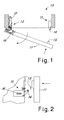
- a door for furniture generally denoted at 10, with a pressure opening.
- the door is hinged to the piece of furniture to be movable between a closed position and an open position by means of articulated hinges 12 and is also provided with a "pull-push" closing device 13 of known type, with release by manual thrust of the door towards the inside.
- the device 13 comprises one portion that is fixed to the piece of furniture and is provided with a coupling element 14 to be fitted into a complementary hooking element 15 fastened to the door.
- the mechanism hooks and unhooks the coupling element 14 to and from the hooking element 15 (in Fig. 2 the hooked position is shown in chain line).
- This mechanism usually provided with a release spring 16, is well known to a person skilled in the art and will not be further described or shown, as it can be easily imagined.
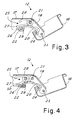
- hinges 12 are advantageously of the quadrilateral type comprising a wing 17 for fastening to the piece of furniture and a bowl 18 for fastening to the inside of the door.
- the quadrilateral hinge comprises an outer connecting rod 19 and a more internal connecting rod 20 the ends 21, 22 and 23, 24 of which are pivotally mounted to the wing and the bowl, respectively.
- At least one of the hinges 12 comprises a spring 25 acting for its movement from the closed position to the open position in the way of pushing the door to the open position against the retaining action in the closed position performed by the pull-push device. In this manner, upon release of the pull-push device the hinge helps in opening the door in a substantial manner.
- the internal connecting rod 20 has an extension 26 on which an arm 27 of the spring exerts pressure starting from the closed position, so as to rotate the connecting rod in the opening direction of the hinge.
- the spring has a second feedback arm 28 exerting pressure on the inside of the wing.
- the spring is spiral wound around a pin (that can be the articulation pin of the connecting rod 19 on the wing) and has an arm 27 (that can be a U-bent central region of the double-spiral spring) exerting pressure on the projection starting from the closed position to at least an important stretch of the opening stroke.
- the extension of the internal connecting rod on which the spring exerts pressure is formed with a tab that is cut out and bent outwards relative to the portion 29 of the connecting rod 20 that is wound up around its pivoting point 22 on the wing.
- Fig. 4 Shown in Fig. 4 is an alternative embodiment according to which the opening thrust substantially goes on until the end of the opening stroke of the hinge.
- the connecting-rod portion 29 that is wound around the pivoting point on the wing comprises a cut-away region 30 so that it does not interfere with the spring itself.
- the cut-away region is advantageously obtained from the same cut-out forming the extension 26.
- the spring is also wound on a pin 31 that is located more towards the back of the wing relative to pin 21. This technique promotes the action of the spring towards the position close to complete opening of the hinge.
- Opening of he door in accordance with the invention takes place always and in any case upon release of the pull-push device by virtue of the opening thrust of the hinge.
- the door costs are not however increased, since separated thrust devices are not used.
Landscapes
- Engineering & Computer Science (AREA)
- Mechanical Engineering (AREA)
- Closing And Opening Devices For Wings, And Checks For Wings (AREA)
- Hinges (AREA)
- Glass Compositions (AREA)
- Steering Control In Accordance With Driving Conditions (AREA)
- Toilet Supplies (AREA)
Abstract
Description
- Fig. 1 is a top view of a door made in accordance with the invention;
- Fig. 2 is a more detailed side view of a particular of the door in Fig. 1;
- Fig. 3 is a section view of a particular of the hinge for the door in accordance with the invention;
- Fig. 4 is a possible alternative embodiment of the hinge in Fig. 3.
Claims (7)
- A door with a pressure opening, comprising articulated hinges (12) for hinging to the piece of furniture and a "pull-push" closing device (13) to be released by manual thrust of the door towards the inside, characterized in that at least one articulated hinge (12) comprises a spring (25) acting for its movement from the closed position to the open position, in the way of pushing the door to the open position against the retaining action in the closed position performed by the pull-push device in order to help in opening the door upon release of the pull-push device.
- A door as claimed in claim 1, characterized in that the at least one articulated hinge (12) is of the quadrilateral type comprising a wing (17) for fastening to the piece of furniture and a bowl (18) for fastening to the inside of the door, with an outer connecting rod (19) and a more internal connecting rod (20) that are pivotally mounted at their ends to the wing and the bowl, the internal connecting rod having an extension (26) on which an arm (27) of said spring exerts pressure to rotate the connecting rod in the opening direction of the hinge.
- A door as claimed in claim 2, characterized in that the spring (25) has a second feedback arm (28) exerting pressure on the inside of the wing.
- A door as claimed in claim 2, characterized in that the spring (25) is wound around a pin (21, 31) supported in the wing.
- A door as claimed in claim 4, characterized in that the winding pin of the spring also embodies the pivoting point (21) of the external connecting rod (19) on the wing.
- A door as claimed in claim 2, characterized in that the extension of the internal connecting rod on which the spring exerts pressure is formed with a tab (26) cut out and bent outwards relative to the portion (29) of this connecting rod that is wound around its pivoting point on the wing.
- A door as claimed in claim 6, characterized in that said portion of the connecting rod that is wound around its pivoting point on the wing comprises a cut-away region (30) so that it does not interfere with the spring exerting pressure on the extension when the hinge is in a position close to full opening.
Applications Claiming Priority (2)
| Application Number | Priority Date | Filing Date | Title |
|---|---|---|---|
| IT000198U ITMI20040198U1 (en) | 2004-04-30 | 2004-04-30 | DOOR WITH PRESSURE OPENING |
| ITMI20040198 | 2004-04-30 |
Publications (3)
| Publication Number | Publication Date |
|---|---|
| EP1591608A1 true EP1591608A1 (en) | 2005-11-02 |
| EP1591608B1 EP1591608B1 (en) | 2014-08-06 |
| EP1591608B9 EP1591608B9 (en) | 2014-11-19 |
Family
ID=35186306
Family Applications (1)
| Application Number | Title | Priority Date | Filing Date |
|---|---|---|---|
| EP20050075931 Expired - Lifetime EP1591608B9 (en) | 2004-04-30 | 2005-04-19 | A furniture door with an opening mechanism and a touch latch device |
Country Status (5)
| Country | Link |
|---|---|
| US (1) | US7905524B2 (en) |
| EP (1) | EP1591608B9 (en) |
| CN (1) | CN1693646A (en) |
| ES (1) | ES2523015T3 (en) |
| IT (1) | ITMI20040198U1 (en) |
Cited By (8)
| Publication number | Priority date | Publication date | Assignee | Title |
|---|---|---|---|---|
| CN103556911A (en) * | 2013-11-21 | 2014-02-05 | 孟祖钢 | Sealed bin gate system driven by gears and provided with limit bulges |
| CN103556909A (en) * | 2013-11-21 | 2014-02-05 | 孟姣姣 | Sealed bin gate system driven by gears and provided with locking stop pin |
| CN103556912A (en) * | 2013-11-21 | 2014-02-05 | 范含晶 | Screw-driven sealing warehouse door system with elastic material arranged inside door sheet cavity |
| CN103556908A (en) * | 2013-11-21 | 2014-02-05 | 俞升洋 | Seal bin gate system driven by slide block and provided with vertical parts filled with elastic materials |
| WO2020236101A1 (en) * | 2019-05-20 | 2020-11-26 | Samet Kalip Ve Madeni̇ Eşya San Ti̇c. A.Ş | Fitting assembly |
| US12000200B2 (en) | 2019-05-20 | 2024-06-04 | Samet Kalip Ve Madeni Esya San Ve Tic. A.S. | Furniture connecting fitting |
| US12044052B2 (en) | 2019-05-20 | 2024-07-23 | Samet Kalip Ve Madeni Esya San Ve Tic. A.S. | Furniture connecting fitting |
| US12270237B2 (en) | 2019-05-20 | 2025-04-08 | Samet Kalip Ve Madeni Esya San Ve Tic. A.S. | Furniture connecting fitting |
Families Citing this family (16)
| Publication number | Priority date | Publication date | Assignee | Title |
|---|---|---|---|---|
| DE202007005957U1 (en) * | 2007-02-19 | 2008-06-26 | Liebherr-Hausgeräte Ochsenhausen GmbH | Fridge and / or freezer |
| TR200903812A1 (en) | 2009-05-15 | 2010-12-21 | Vestel Beyaz Eşya Sanayi̇ Ve Ti̇caret Anoni̇m Şi̇rketi̇@ | Drawer mounting hinge |
| AT508698B1 (en) * | 2009-08-20 | 2017-07-15 | Blum Gmbh Julius | FURNITURE WITH PLATE ARRANGEMENT |
| DE102011052355B4 (en) * | 2011-08-02 | 2022-04-28 | Dongtai Hardware Precision (Hong Kong) Limited | Device for opening the cabinet door of a cabinet body |
| DE102011082369B4 (en) * | 2011-09-08 | 2016-03-24 | Siemens Aktiengesellschaft | Locking device and a medical imaging device with the locking device |
| TWI435681B (en) * | 2011-12-30 | 2014-04-21 | Pegatron Corp | Electronic apparatus and hinge structure thereof |
| CN102561901A (en) * | 2012-01-12 | 2012-07-11 | 林智勇 | Anti-pinch safe door |
| US9101086B2 (en) * | 2013-01-15 | 2015-08-04 | Blackberry Limited | Access panels for electronic devices |
| DE102013112705A1 (en) * | 2013-11-18 | 2015-05-21 | Illinois Tool Works Inc. | System of a component and an actuating device for the component |
| DE102013112998B4 (en) * | 2013-11-25 | 2021-10-21 | Sartorius Lab Instruments Gmbh & Co. Kg | Cover of a draft shield of a precision balance and a draft shield for a precision balance |
| AT515216B1 (en) * | 2014-05-02 | 2015-07-15 | Blum Gmbh Julius | Actuator for furniture flaps |
| AT516391B1 (en) * | 2015-06-09 | 2016-05-15 | Blum Gmbh Julius | Ejecting device for a movable furniture part |
| US10577839B2 (en) * | 2015-06-11 | 2020-03-03 | Inteva Products, Llc | Over center mechanism and method of use |
| RU188898U1 (en) * | 2019-03-04 | 2019-04-29 | Борис Леонидович Киселев | CLAMPING DEVICE FOR FIXING OPENING ELEMENT |
| JP7539640B2 (en) * | 2021-01-29 | 2024-08-26 | マツ六株式会社 | Door control structure |
| TWI889918B (en) * | 2021-10-13 | 2025-07-11 | 日商文化捲門股份有限公司 | Connection device of building materials, connection structure and connection method thereof |
Citations (3)
| Publication number | Priority date | Publication date | Assignee | Title |
|---|---|---|---|---|
| DE2851774A1 (en) * | 1977-12-30 | 1980-06-12 | Hettich Hetal Werke | Furniture door hinge unit - has two hinge parts connected by spring loaded link element with angled off tongue |
| US4215884A (en) * | 1979-01-08 | 1980-08-05 | Weber-Knapp Company | Touch latch |
| DE10152699A1 (en) * | 2001-10-19 | 2003-04-30 | Grass Gmbh Hoechst | Hinge for furniture doors with opening mechanism has strap with inner and outer articulated levers ;inked by bolts, arm, base plate and spring element |
Family Cites Families (7)
| Publication number | Priority date | Publication date | Assignee | Title |
|---|---|---|---|---|
| US2941831A (en) * | 1956-12-07 | 1960-06-21 | Borsani Giancarlo | Spring catches |
| DE2117828C3 (en) * | 1970-11-09 | 1982-09-16 | Arturo Salice S.p.A., Cantu, Como | Hinge joint for doors, flaps or the like. |
| IT1093464B (en) * | 1978-04-04 | 1985-07-19 | Salice Arturo Spa | CLOSING DEVICE OF A HINGE FOR FURNITURE |
| AT407416B (en) * | 1999-04-28 | 2001-03-26 | Blum Gmbh Julius | HINGE WITH A HINGE ARM |
| DE10154699B4 (en) | 2001-11-09 | 2004-04-08 | MAX-PLANCK-Gesellschaft zur Förderung der Wissenschaften e.V. | Method and device for stimulating an optical transition in a spatially limited manner |
| DE20212022U1 (en) * | 2002-08-05 | 2002-09-26 | Arturo Salice S.P.A., Novedrate, Como | hinge |
| ITRM20030086U1 (en) * | 2003-05-14 | 2004-11-15 | Salice Arturo Spa | HINGE WITH SPRING FOR FURNITURE. |
-
2004
- 2004-04-30 IT IT000198U patent/ITMI20040198U1/en unknown
-
2005
- 2005-04-19 ES ES05075931.5T patent/ES2523015T3/en not_active Expired - Lifetime
- 2005-04-19 EP EP20050075931 patent/EP1591608B9/en not_active Expired - Lifetime
- 2005-04-22 US US11/113,165 patent/US7905524B2/en not_active Expired - Fee Related
- 2005-04-29 CN CNA2005100670998A patent/CN1693646A/en active Pending
Patent Citations (3)
| Publication number | Priority date | Publication date | Assignee | Title |
|---|---|---|---|---|
| DE2851774A1 (en) * | 1977-12-30 | 1980-06-12 | Hettich Hetal Werke | Furniture door hinge unit - has two hinge parts connected by spring loaded link element with angled off tongue |
| US4215884A (en) * | 1979-01-08 | 1980-08-05 | Weber-Knapp Company | Touch latch |
| DE10152699A1 (en) * | 2001-10-19 | 2003-04-30 | Grass Gmbh Hoechst | Hinge for furniture doors with opening mechanism has strap with inner and outer articulated levers ;inked by bolts, arm, base plate and spring element |
Cited By (14)
| Publication number | Priority date | Publication date | Assignee | Title |
|---|---|---|---|---|
| CN103556911A (en) * | 2013-11-21 | 2014-02-05 | 孟祖钢 | Sealed bin gate system driven by gears and provided with limit bulges |
| CN103556909A (en) * | 2013-11-21 | 2014-02-05 | 孟姣姣 | Sealed bin gate system driven by gears and provided with locking stop pin |
| CN103556912A (en) * | 2013-11-21 | 2014-02-05 | 范含晶 | Screw-driven sealing warehouse door system with elastic material arranged inside door sheet cavity |
| CN103556908A (en) * | 2013-11-21 | 2014-02-05 | 俞升洋 | Seal bin gate system driven by slide block and provided with vertical parts filled with elastic materials |
| CN103556909B (en) * | 2013-11-21 | 2015-05-20 | 叶葵 | Sealed bin gate system driven by gears and provided with locking stop pin |
| CN103556908B (en) * | 2013-11-21 | 2015-06-03 | 俞升洋 | Seal bin gate system driven by slide block and provided with vertical parts filled with elastic materials |
| CN103556912B (en) * | 2013-11-21 | 2015-06-03 | 方小勤 | Screw-driven sealing warehouse door system with elastic material arranged inside door sheet cavity |
| WO2020236101A1 (en) * | 2019-05-20 | 2020-11-26 | Samet Kalip Ve Madeni̇ Eşya San Ti̇c. A.Ş | Fitting assembly |
| CN113840969A (en) * | 2019-05-20 | 2021-12-24 | 沙美卡尺和矿业灯具有限公司 | Accessory device |
| US11808074B2 (en) | 2019-05-20 | 2023-11-07 | Samet Kalip Ve Madeni Esya San Ve Tic. A.S. | Fitting arrangement |
| US12000200B2 (en) | 2019-05-20 | 2024-06-04 | Samet Kalip Ve Madeni Esya San Ve Tic. A.S. | Furniture connecting fitting |
| US12044052B2 (en) | 2019-05-20 | 2024-07-23 | Samet Kalip Ve Madeni Esya San Ve Tic. A.S. | Furniture connecting fitting |
| US12270237B2 (en) | 2019-05-20 | 2025-04-08 | Samet Kalip Ve Madeni Esya San Ve Tic. A.S. | Furniture connecting fitting |
| EP4112854B1 (en) * | 2019-05-20 | 2025-11-26 | Samet Kalip Ve Madeni Esya San. Ve Tic. A.S. | Fitting device |
Also Published As
| Publication number | Publication date |
|---|---|
| EP1591608B9 (en) | 2014-11-19 |
| ITMI20040198U1 (en) | 2004-07-30 |
| ES2523015T3 (en) | 2014-11-20 |
| US7905524B2 (en) | 2011-03-15 |
| CN1693646A (en) | 2005-11-09 |
| EP1591608B1 (en) | 2014-08-06 |
| US20050242593A1 (en) | 2005-11-03 |
Similar Documents
| Publication | Publication Date | Title |
|---|---|---|
| EP1591608B1 (en) | A furniture door with an opening mechanism and a touch latch device | |
| US8419106B2 (en) | Lid opening and closing apparatus | |
| CN101680475B (en) | Spring hook with moving pawl in wire form | |
| US8713760B2 (en) | Hinge for a furniture part and piece of furniture | |
| JP2001115719A (en) | Lockable rotating and / or sliding wing system | |
| US7197790B1 (en) | Hinge including a gas strut | |
| JP2002227513A (en) | Lifting device for folding double door | |
| CN114737833B (en) | Hidden automobile outer handle structure | |
| EP0807740A3 (en) | Double swing door opening/closing mechanism | |
| CA2621437A1 (en) | Double locking snap hook | |
| EP2762665A2 (en) | A pivot hinge fitting with engagement means and a roof window comprising a set of such pivot hinge fittings | |
| US20020109445A1 (en) | Safety lid or door for household appliances | |
| US6539581B1 (en) | Hinge for furniture and the like, with movable arm arranged inside the fixed arm | |
| WO2019015694A1 (en) | Linked cover opening assembly and top-loading horizontal axis washing machine | |
| EP1508663A1 (en) | An improved pivot window with at least one auxiliary opening device | |
| JP4327667B2 (en) | Closing device | |
| JP2005336983A5 (en) | ||
| EP2616612B1 (en) | A lock assembly | |
| US6811208B1 (en) | Self-camming torque rod assembly for vehicles | |
| JP4762648B2 (en) | Window device lock device | |
| CN105986713B (en) | Hood hinge for vehicle | |
| US20060000057A1 (en) | Charlie the doorman an automatic storm door holding open device retrofitable to existing air over spring cylinder door closers | |
| KR100868154B1 (en) | Outside Handle Structure of Vehicle Tailgate | |
| US5356186A (en) | Latch mechanism for a home appliance | |
| CN210828778U (en) | Automatic hinge for door and window |
Legal Events
| Date | Code | Title | Description |
|---|---|---|---|
| PUAI | Public reference made under article 153(3) epc to a published international application that has entered the european phase |
Free format text: ORIGINAL CODE: 0009012 |
|
| AK | Designated contracting states |
Kind code of ref document: A1 Designated state(s): AT BE BG CH CY CZ DE DK EE ES FI FR GB GR HU IE IS IT LI LT LU MC NL PL PT RO SE SI SK TR |
|
| AX | Request for extension of the european patent |
Extension state: AL BA HR LV MK YU |
|
| 17P | Request for examination filed |
Effective date: 20060330 |
|
| AKX | Designation fees paid |
Designated state(s): DE ES FR GB IT |
|
| 17Q | First examination report despatched |
Effective date: 20070404 |
|
| RAP1 | Party data changed (applicant data changed or rights of an application transferred) |
Owner name: AGOSTINO FERRARI S.P.A. |
|
| GRAP | Despatch of communication of intention to grant a patent |
Free format text: ORIGINAL CODE: EPIDOSNIGR1 |
|
| INTG | Intention to grant announced |
Effective date: 20140218 |
|
| GRAS | Grant fee paid |
Free format text: ORIGINAL CODE: EPIDOSNIGR3 |
|
| GRAA | (expected) grant |
Free format text: ORIGINAL CODE: 0009210 |
|
| AK | Designated contracting states |
Kind code of ref document: B1 Designated state(s): DE ES FR GB IT |
|
| RAP1 | Party data changed (applicant data changed or rights of an application transferred) |
Owner name: ACCESSORIO SRL IN LIQUIDAZIONE |
|
| REG | Reference to a national code |
Ref country code: GB Ref legal event code: FG4D |
|
| REG | Reference to a national code |
Ref country code: DE Ref legal event code: R096 Ref document number: 602005044392 Country of ref document: DE Effective date: 20140918 |
|
| REG | Reference to a national code |
Ref country code: ES Ref legal event code: FG2A Ref document number: 2523015 Country of ref document: ES Kind code of ref document: T3 Effective date: 20141120 |
|
| REG | Reference to a national code |
Ref country code: DE Ref legal event code: R097 Ref document number: 602005044392 Country of ref document: DE |
|
| PLBE | No opposition filed within time limit |
Free format text: ORIGINAL CODE: 0009261 |
|
| STAA | Information on the status of an ep patent application or granted ep patent |
Free format text: STATUS: NO OPPOSITION FILED WITHIN TIME LIMIT |
|
| 26N | No opposition filed |
Effective date: 20150507 |
|
| REG | Reference to a national code |
Ref country code: FR Ref legal event code: PLFP Year of fee payment: 11 |
|
| GBPC | Gb: european patent ceased through non-payment of renewal fee |
Effective date: 20150419 |
|
| PG25 | Lapsed in a contracting state [announced via postgrant information from national office to epo] |
Ref country code: GB Free format text: LAPSE BECAUSE OF NON-PAYMENT OF DUE FEES Effective date: 20150419 |
|
| REG | Reference to a national code |
Ref country code: FR Ref legal event code: PLFP Year of fee payment: 12 |
|
| REG | Reference to a national code |
Ref country code: FR Ref legal event code: PLFP Year of fee payment: 13 |
|
| REG | Reference to a national code |
Ref country code: FR Ref legal event code: PLFP Year of fee payment: 14 |
|
| PGFP | Annual fee paid to national office [announced via postgrant information from national office to epo] |
Ref country code: FR Payment date: 20190313 Year of fee payment: 15 |
|
| PGFP | Annual fee paid to national office [announced via postgrant information from national office to epo] |
Ref country code: AT Payment date: 20190425 Year of fee payment: 7 Ref country code: ES Payment date: 20190503 Year of fee payment: 15 |
|
| PGFP | Annual fee paid to national office [announced via postgrant information from national office to epo] |
Ref country code: IT Payment date: 20200424 Year of fee payment: 16 |
|
| REG | Reference to a national code |
Ref country code: DE Ref legal event code: R119 Ref document number: 602005044392 Country of ref document: DE |
|
| PG25 | Lapsed in a contracting state [announced via postgrant information from national office to epo] |
Ref country code: DE Free format text: LAPSE BECAUSE OF NON-PAYMENT OF DUE FEES Effective date: 20201103 Ref country code: FR Free format text: LAPSE BECAUSE OF NON-PAYMENT OF DUE FEES Effective date: 20200430 |
|
| REG | Reference to a national code |
Ref country code: ES Ref legal event code: FD2A Effective date: 20210901 |
|
| PG25 | Lapsed in a contracting state [announced via postgrant information from national office to epo] |
Ref country code: ES Free format text: LAPSE BECAUSE OF NON-PAYMENT OF DUE FEES Effective date: 20200420 |
|
| PG25 | Lapsed in a contracting state [announced via postgrant information from national office to epo] |
Ref country code: IT Free format text: LAPSE BECAUSE OF NON-PAYMENT OF DUE FEES Effective date: 20200419 |
|
| PG25 | Lapsed in a contracting state [announced via postgrant information from national office to epo] |
Ref country code: IT Free format text: LAPSE BECAUSE OF NON-PAYMENT OF DUE FEES Effective date: 20210419 |