EP1592501B1 - Dispositif de production de granules - Google Patents
Dispositif de production de granules Download PDFInfo
- Publication number
- EP1592501B1 EP1592501B1 EP04707900A EP04707900A EP1592501B1 EP 1592501 B1 EP1592501 B1 EP 1592501B1 EP 04707900 A EP04707900 A EP 04707900A EP 04707900 A EP04707900 A EP 04707900A EP 1592501 B1 EP1592501 B1 EP 1592501B1
- Authority
- EP
- European Patent Office
- Prior art keywords
- drum
- bearing
- stop
- axis
- collar
- Prior art date
- Legal status (The legal status is an assumption and is not a legal conclusion. Google has not performed a legal analysis and makes no representation as to the accuracy of the status listed.)
- Expired - Lifetime
Links
Images


Classifications
-
- B—PERFORMING OPERATIONS; TRANSPORTING
- B01—PHYSICAL OR CHEMICAL PROCESSES OR APPARATUS IN GENERAL
- B01J—CHEMICAL OR PHYSICAL PROCESSES, e.g. CATALYSIS OR COLLOID CHEMISTRY; THEIR RELEVANT APPARATUS
- B01J2/00—Processes or devices for granulating materials, e.g. fertilisers in general; Rendering particulate materials free flowing in general, e.g. making them hydrophobic
- B01J2/20—Processes or devices for granulating materials, e.g. fertilisers in general; Rendering particulate materials free flowing in general, e.g. making them hydrophobic by expressing the material, e.g. through sieves and fragmenting the extruded length
-
- B—PERFORMING OPERATIONS; TRANSPORTING
- B29—WORKING OF PLASTICS; WORKING OF SUBSTANCES IN A PLASTIC STATE IN GENERAL
- B29B—PREPARATION OR PRETREATMENT OF THE MATERIAL TO BE SHAPED; MAKING GRANULES OR PREFORMS; RECOVERY OF PLASTICS OR OTHER CONSTITUENTS OF WASTE MATERIAL CONTAINING PLASTICS
- B29B9/00—Making granules
- B29B9/10—Making granules by moulding the material, i.e. treating it in the molten state
Definitions
- the invention relates to a device for the production of granules with a perforated rotating drum with a feeder for flowable masses in the interior, the outlet openings on the lower circumference of the drum to cover with their holes, and with a arranged below the rotating drum cooling belt, to which the fall from the drum in drop form emerging masses and solidify, wherein the drum is supported on support arms which are pivotable about an axis parallel to the axis of the drum extending axis.
- a device for producing granules is known from DE 28 53 054 C3 known. These known on the market under the name Rotoformer devices have been proven for the processing of a variety of melts to granules.
- the rotating drum is supported by means of a support frame on both sides above the cooling belt.
- a security risk can occur because the fixed arranged above the cooling belt rotoformer together with the cooling belt forms a nip, which can lead to damage to the device, possibly even injury to operators.
- German patent application DE 34 21 625 A1 is a device for producing granules with a perforated rotating drum with a feeder for flowable masses in the interior, the outlet openings on the lower circumference of the drum come to cover with their holes, and with a arranged below the rotating drum cooling belt, on which the tumble and solidify in tumbling masses of the drum.
- the drum is supported on support arms pivotable about an axis parallel to the axis of the drum. A position of the brackets can be adjusted with a set screw.
- the present invention is therefore based on the object, a device of the type mentioned in such a way that on the one hand a simple assembly and disassembly of the rotating drum is possible and that on the other hand a safe operation is possible.
- one of the support arms has a pivotable about an axis perpendicular to the pivot axis and in its vicinity part and that the pivotable part of the pivot arm provided with an attacking on an end face of the drum storage is.
- the drum By the drum is held on pivotable support arms, the drum can be easily swung up and away from the cooling belt when maintenance or the like to be performed. On the other hand, it is also possible in this way, the distance of the rotating drum to To set the cooling belt easy and, if in further development of the invention, the drum is positioned by a arranged on a support frame stop against which the support arms are pressed, also give the opportunity that the rotating drum is automatically pivoted upward when objects in the nip be drawn in.
- one of the support arms is pivotable about an axis perpendicular to the pivot axis and in its vicinity extending axis.
- This pivotal support arm can then be provided with an attacking on an end face of the drum storage, so that for disassembly or for assembly in a simple manner, the accessibility of the drum for the purpose of peeling is achieved by simply pivoting a Tragarmmaschines.
- the bearing can be rotatably arranged about a connecting pin, which can be fastened on the swivel arm and on the feed device.
- the bearing can have a front side insertable into the drum bearing plate, which is axially withdrawn from the drum and with the help of the connecting pin, which may also be axially removable from the feeder removable.
- the connecting pin provided with a stop which axially entrains the bearing plate during axial withdrawal from the feeder, then the subsequent Abschwenkvorgang the Schwenkarmwels is possible in a simple manner.
- the end shield itself can be held in an expedient embodiment via an axial sleeve in pivot bearings, which are attached to the support arm, and it can provide the axial sleeve with a cooperating with the stop of the connecting pin collar.
- pivot bearings which are attached to the support arm, and it can provide the axial sleeve with a cooperating with the stop of the connecting pin collar.
- the new design allows for better accessibility to maintenance, increases the security of the device during operation and allows easy Einjusttician the distance of the rotating drum from the cooling belt.
- the stop can be designed to be adjustable for this purpose.
- the support arms may be part of a rocker whose projecting beyond the pivot axis arms are connected to each other by a cross bar.
- the drive motor for the drum which is usually connected via a chain drive with a drive wheel of the drum, be arranged on the crossbar, so that a certain weight balance is achieved on the rocker, which ensures that the rocker can be pivoted with the rotating drum arranged thereon without much effort.
- the Fig. 1 shows a granulating device, which is equipped with a rotating perforated drum 1, which in turn is driven by a chain drive 2 of an equipped with a gearbox 3 electric motor 4.
- the rotating drum 1 is mounted on pivoting arms 5, 6, which are part of a rocker 7, which is pivotable about the axis 8, which in turn is parallel to the axis of rotation 9 of the drum 1.
- the drive motor 4 is seated on a connecting bracket 10 of the rocker 7, which is on the, seen from the rotating drum 1, opposite side of the pivot axis 8.
- the weight of the drive motor 4 and the transmission in this type of arrangement is a counterbalance to the rotating drum 1 and to the feed tube extending therethrough represents for the mass to be dripped, of which a part 11 protrudes laterally from the drum 1.
- the mass to be dripped usually a melt, supplied in a manner not shown in detail, and then discharged at the bottom of the rotating drum 1 on a transport or cooling belt 12 down, which in the illustration Fig. 1 is drawn transparent to detect the lying below the rotating drum 1 deflecting roller 13.
- Both the rocker 7 with its parts, as well as the guide roller 13 are mounted on a support frame 14.
- the uppermost longitudinal beam 15 of this support frame 14 is provided on each side with a stop 16 which is adjustable in height.
- the rocker 7 is acted upon by a pneumatic cylinder 17 in a counterclockwise direction so that their lever arms 5 and 6 or parts of the mounted on them bearing 18 come to rest on the stop 16.
- the height of the rotating drum 1 above the belt 12 can be adjusted defined.
- feed and discharge lines 19, 20 for a heating medium are provided in a manner known per se, which flows in a known manner within the feed tube.
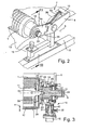
- FIGS. 2 and 3 let recognize that the bearing 18 which is fixed to the pivot arm 6, is arranged centrally around a connecting pin 21, whose axis coincides with the axis of rotation 9 of the drum 1.
- the connecting pin 21 is rotatably mounted and has at its outwardly projecting end a corrugated end cap 22 or a corresponding actuator and at its inner end a thread 23, with which it is screwed onto a threaded pin 24 of the fixed inner tube 11 to the Stable inner tube stable.
- the screw pin 24 and the connecting pin 21 are also still provided with a guide cone 25, which ensures the alignment and the connection of pin 21 and inner tube 11.
- a sleeve 26 Radially within the bearing 18, a sleeve 26 is provided, which is centered, but axially displaceable within the bearing 18 is held and which has at its left end a bearing plate 27 with an axially projecting into the front end of the drum 1 collar 28.
- shield 27 On the shield 27 on the one hand and on the inner tube 11 on the other hand shield shells and plates are provided, which ensure that the cone 25 and the thread 23 are covered as possible with respect to the prevailing inside the drum 1 atmosphere.
- Fig. 2 To recognize is off Fig. 2 in that the rocker 7 in the position after Fig. 2 is lifted from the stop 16 and after a pivoting in the counterclockwise direction - which takes place by means of the pneumatic cylinder 17 - according to Fig. 3 rests on the stop 16, so that in this way the distance a between the drum circumference 1 and the cooling belt 12 is fixed and secure.
- the stop 16 is designed for this purpose so that it is adjustable in height. This can for example be done by a screw sleeve 30 is mounted on a fixed bolt 31 and allows the adjustment, wherein the set distance is then secured by a clamping screw 32.
- the Fig. 2 but can also recognize a pivot lever 33, which is provided with two mutually parallel walls and the upper edge of the pivot lever 6 engages over during operation, as in Fig. 1 is shown.
- the pivot lever 6 is provided to support the bearing 18 with a lever part 6a, which is pivotable about an axis 35 which in the vicinity of the pivot axis 8 perpendicular to this runs.
- the purpose of this swing-lever part 6a is to remove the bearing 18 in a simple manner from the drum 1, for example, to maintain or replace them.
- the pivot lever 33 secures in position Fig. 1 the lever part 6a aligned in alignment with the pivot 6. To remove the bearing 18 from the drum of the pivot lever 33 is in its position Fig. 2 swung up in the direction of the arrow 38.
- the bearing shell 29 has then also the protective plate 30 is released, and it can after the pivoting of the safety lever 33 in the direction of the arrow 38, which can take place only after the release of the collar 28 from the drum, the part 6a of the pivot lever 6, as in Fig. 4 shown, swung with the bearing 18 to the right and that to the position after Fig. 5 in which then the axial removal of the drum 1 from the arranged on the opposite side storage without problems is possible.
- the inner tube 11 with an attached adapter piece 39 is then also accessible for maintenance, such as Fig. 6 shows.
Landscapes
- Chemical & Material Sciences (AREA)
- Organic Chemistry (AREA)
- Chemical Kinetics & Catalysis (AREA)
- Engineering & Computer Science (AREA)
- Mechanical Engineering (AREA)
- Processing And Handling Of Plastics And Other Materials For Molding In General (AREA)
- Glanulating (AREA)
- Processing Of Solid Wastes (AREA)
- Crushing And Grinding (AREA)
- Rolls And Other Rotary Bodies (AREA)
Abstract
Claims (13)
- Dispositif de production de granulés comprenant un tambour rotatif perforé (1) avec un dispositif d'alimentation (11) pour des masses coulantes à l'intérieur, dont les orifices de sortie viennent couvrir sur la circonférence inférieure du tambour (1) les perforations de ce dernier, ainsi qu'un tapis refroidissant (12) disposé au-dessous du tambour rotatif, sur lequel les masses sortant du tambour perforé sous forme de gouttes tombent et se solidifient, sachant que le tambour (1) est maintenu par des bras porteurs (5, 6) qui peuvent être pivotés autour d'un axe (8) s'étendant parallèlement à l'axe (9) du tambour (1), caractérisé en ce qu'un des bras porteurs (6) présente une partie (6a) pouvant être pivotée autour d'un axe (35) s'étendant perpendiculairement à l'axe de pivotement (8) et à proximité de celui-ci, et que la partie (6a) du bras pivotant est dotée d'un palier (18) s'engageant sur une face frontale du tambour (1).
- Dispositif selon la revendication 1, caractérisé en ce que le tambour (1) est positionné par une butée (16) disposée sur un cadre porteur (14) et contre laquelle les bras porteurs (5, 6) sont appuyés.
- Dispositif selon la revendication 2, caractérisé en ce que la butée (16) est réglable.
- Dispositif selon la revendication 1, caractérisé en ce que les bras porteurs (5, 6) font partie d'une bascule (7), dont les bras dépassant de l'axe de pivotement (8) sont reliés entre eux par une barre transversale (10).
- Dispositif selon la revendication 4, caractérisé en ce que le moteur d'entraînement (4) pour le tambour (1) est disposé sur la barre transversale (10).
- Dispositif selon la revendication 5, caractérisé en ce que le moteur d'entraînement (4) est relié à une roue menante du tambour (1) par l'intermédiaire d'une transmission par chaîne (2).
- Dispositif selon la revendication 1, caractérisé en ce que le palier (18) présente une partie interne rotative, qui entoure un tourillon de liaison (21) pouvant être fixé au bras pivotant (6a) et au dispositif d'alimentation (11).
- Dispositif selon la revendication 1, caractérisé en ce que le manchon (26) disposé dans le palier (18) présente un flasque (27) avec un collet (28) pouvant être introduit dans le tambour du côté frontal.
- Dispositif selon la revendication 8, caractérisé en ce que le flasque (27) et le collet (28) sont disposés de manière à pouvoir être extraits axialement du tambour (1).
- Dispositif selon la revendication 7, caractérisé en ce que le tourillon de liaison (21) est conçu de manière à pouvoir être détaché axialement du dispositif d'alimentation (11).
- Dispositif selon la revendication 10, caractérisé en ce que le tourillon de liaison (21) est vissé sur une goupille filetée (24) du dispositif d'alimentation (11).
- Dispositif selon la revendication 11, caractérisé en ce que le tourillon de liaison (21) est pourvu d'une butée (36) qui entraîne le flasque (27) et le collet (28) lors du retrait axial du dispositif d'alimentation (11).
- Dispositif selon la revendication 12, caractérisé en ce que le flasque (27) et le collet (28) sont maintenus, par l'intermédiaire d'un manchon axial (26), dans le palier (18), lequel est fixé au bras porteur (6), et que le manchon axial (26) est doté d'un collet (37) agissant en interaction avec la butée (36) du tourillon de liaison (21).
Applications Claiming Priority (3)
| Application Number | Priority Date | Filing Date | Title |
|---|---|---|---|
| DE10306688A DE10306688B3 (de) | 2003-02-11 | 2003-02-11 | Vorrichtung zur Herstellung von Granulat |
| DE10306688 | 2003-02-11 | ||
| PCT/EP2004/000983 WO2004071648A1 (fr) | 2003-02-11 | 2004-02-04 | Procede de production de granulats |
Publications (2)
| Publication Number | Publication Date |
|---|---|
| EP1592501A1 EP1592501A1 (fr) | 2005-11-09 |
| EP1592501B1 true EP1592501B1 (fr) | 2012-05-30 |
Family
ID=32863826
Family Applications (1)
| Application Number | Title | Priority Date | Filing Date |
|---|---|---|---|
| EP04707900A Expired - Lifetime EP1592501B1 (fr) | 2003-02-11 | 2004-02-04 | Dispositif de production de granules |
Country Status (9)
| Country | Link |
|---|---|
| US (1) | US7344368B2 (fr) |
| EP (1) | EP1592501B1 (fr) |
| JP (1) | JP4627753B2 (fr) |
| KR (1) | KR100991126B1 (fr) |
| CN (1) | CN100361740C (fr) |
| CA (1) | CA2515958C (fr) |
| DE (1) | DE10306688B3 (fr) |
| RU (1) | RU2358797C2 (fr) |
| WO (1) | WO2004071648A1 (fr) |
Families Citing this family (3)
| Publication number | Priority date | Publication date | Assignee | Title |
|---|---|---|---|---|
| DE102007061408A1 (de) * | 2007-12-11 | 2009-06-18 | Sandvik Materials Technology Deutschland Gmbh | Verfahren und Tropfenformer zum Herstellen von Pastillen sowie Verfahren zum Herstellen eines schwefelhaltigen Düngers |
| AT511804B1 (de) * | 2011-11-17 | 2013-03-15 | Berndorf Band Gmbh | Vorrichtung zur herstellung einer platte aus kunststeinmaterial |
| CN116328645A (zh) * | 2023-03-02 | 2023-06-27 | 上海瑞宝造粒机有限公司 | 一种造粒机 |
Family Cites Families (10)
| Publication number | Priority date | Publication date | Assignee | Title |
|---|---|---|---|---|
| EP0012192B1 (fr) * | 1978-12-08 | 1983-01-12 | Santrade Ltd. | Dispositif pour extruder des masses fluides d'un récipient |
| DE2853054C3 (de) | 1978-12-08 | 1982-09-09 | Santrade Ltd., 6002 Luzern | Vorrichtung zum Auspressen von fließfähigen Massen |
| DE3421625C2 (de) * | 1984-06-09 | 1986-09-04 | Santrade Ltd., Luzern | Vorrichtung zur Herstellung von Granulat |
| SU1323230A1 (ru) * | 1985-11-20 | 1987-07-15 | Предприятие П/Я Р-6543 | Устройство дл дозировани сыпучих материалов |
| DE4032683C3 (de) * | 1990-10-15 | 1996-06-13 | Santrade Ltd | Vorrichtung zur Bildung von Tropfen |
| DE4119021C1 (fr) * | 1991-06-09 | 1992-08-13 | Santrade Ltd., Luzern, Ch | |
| JP2547835Y2 (ja) * | 1992-06-26 | 1997-09-17 | 新東工業株式会社 | 転動撹拌造粒装置 |
| AT398635B (de) * | 1992-08-28 | 1995-01-25 | Berndorf Band Gmbh | Vorrichtung zur portionierten abgabe von fliessfähigen massen |
| DE4244035C1 (de) * | 1992-12-24 | 1994-02-03 | Santrade Ltd | Vorrichtung zur Herstellung von Granulat |
| DE4419491C1 (de) * | 1994-06-03 | 1995-05-11 | Santrade Ltd | Vorrichtung zum streifen- oder tropfenförmigen Ausbringen fließfähiger Massen auf ein Transportband |
-
2003
- 2003-02-11 DE DE10306688A patent/DE10306688B3/de not_active Expired - Fee Related
-
2004
- 2004-02-04 US US10/545,000 patent/US7344368B2/en not_active Expired - Fee Related
- 2004-02-04 CA CA2515958A patent/CA2515958C/fr not_active Expired - Fee Related
- 2004-02-04 EP EP04707900A patent/EP1592501B1/fr not_active Expired - Lifetime
- 2004-02-04 RU RU2005127263/15A patent/RU2358797C2/ru not_active IP Right Cessation
- 2004-02-04 KR KR1020057014162A patent/KR100991126B1/ko not_active Expired - Fee Related
- 2004-02-04 CN CNB2004800039538A patent/CN100361740C/zh not_active Expired - Fee Related
- 2004-02-04 WO PCT/EP2004/000983 patent/WO2004071648A1/fr not_active Ceased
- 2004-02-04 JP JP2006501721A patent/JP4627753B2/ja not_active Expired - Fee Related
Also Published As
| Publication number | Publication date |
|---|---|
| US20060210661A1 (en) | 2006-09-21 |
| JP2006517145A (ja) | 2006-07-20 |
| WO2004071648A1 (fr) | 2004-08-26 |
| JP4627753B2 (ja) | 2011-02-09 |
| CN1747780A (zh) | 2006-03-15 |
| DE10306688B3 (de) | 2004-11-11 |
| RU2005127263A (ru) | 2006-01-27 |
| KR100991126B1 (ko) | 2010-11-01 |
| KR20050103286A (ko) | 2005-10-28 |
| EP1592501A1 (fr) | 2005-11-09 |
| CN100361740C (zh) | 2008-01-16 |
| CA2515958C (fr) | 2011-06-14 |
| CA2515958A1 (fr) | 2004-08-26 |
| RU2358797C2 (ru) | 2009-06-20 |
| US7344368B2 (en) | 2008-03-18 |
Similar Documents
| Publication | Publication Date | Title |
|---|---|---|
| DE3421625C2 (de) | Vorrichtung zur Herstellung von Granulat | |
| DE112011102325B4 (de) | Walzverdichtungsfahrzeug | |
| DE2600648A1 (de) | Pelletpresse | |
| DE60112529T2 (de) | Vorrichtung zum bewegen und orientieren von sprühdüsen in einer beschichtungstrommel | |
| EP0739235A1 (fr) | Dispositif de production de pastilles | |
| EP1592501B1 (fr) | Dispositif de production de granules | |
| DE1632081C3 (de) | Vorrichtung zum Entfernen von Knochen aus Fleischstucken | |
| EP0603702B1 (fr) | Appareil pour produire des granules | |
| DE3731150C2 (de) | Verfahren und Vorrichtung zum Granulieren von Schwefel | |
| EP0712331B1 (fr) | Dispositif permettant de charger sous forme de bandes ou de gouttes des materiaux coulants sur une bande transporteuse | |
| EP0355745B1 (fr) | Dispositif de fabrication de grains de glace | |
| EP0603701B1 (fr) | Appareil pour mettre sous forme de rubans ou de gouttelettes des masses fluides | |
| DE658785C (de) | Vorrichtung zum Ausgiessen von Lagern | |
| EP3546871B1 (fr) | Dispositif de séparation permettant de séparer une matière solide à partir d'un dflux de refoulement et procédé de maintenance d'un tel dispositif de séparation | |
| DE2416818A1 (de) | Rotationsgiessmaschine zum herstellen von formkoerpern aus kunststoff | |
| EP0668794B1 (fr) | Dispositif permettant de recouvrir des particules solides | |
| DE102024114210A1 (de) | Tropfenformer und Vorrichtung mit einem Tropfenformer | |
| EP1412071A1 (fr) | Dispositif pour l'expression de matieres coulantes et procede pour la production d'un tel dispositif | |
| DE2719334C2 (de) | Vorrichtung zum axialen Zu- oder Abführen zu oder aus einer Bearbeitungseinrichtung und zum Ausrichten und/oder Vereinzeln von durch einen radialen Stoßspalt geschlitzten Ringen | |
| DE1914881B (fr) | ||
| DE1296946B (de) | Kontinuierlich arbeitende Zentrifugal-Kugelmuehle | |
| DE102008048114A1 (de) | Durchlauf-Sprüheinrichtung | |
| DE1227838B (de) | Vorrichtung zum Entleerung eines Silos | |
| DD159553A1 (de) | Spinnduesenpaket zum schmelzspinnen von synthetischen hochpolymeren | |
| DE1939871A1 (de) | Vorrichtung zur Herstellung eines Kunststoffgranulates |
Legal Events
| Date | Code | Title | Description |
|---|---|---|---|
| PUAI | Public reference made under article 153(3) epc to a published international application that has entered the european phase |
Free format text: ORIGINAL CODE: 0009012 |
|
| 17P | Request for examination filed |
Effective date: 20050714 |
|
| AK | Designated contracting states |
Kind code of ref document: A1 Designated state(s): AT BE BG CH CY CZ DE DK EE ES FI FR GB GR HU IE IT LI LU MC NL PT RO SE SI SK TR |
|
| AX | Request for extension of the european patent |
Extension state: AL LT LV MK |
|
| DAX | Request for extension of the european patent (deleted) | ||
| RIN1 | Information on inventor provided before grant (corrected) |
Inventor name: NOCELLA, ROGER Inventor name: HAEFELE, DIETMAR Inventor name: GIERKE, STEPHAN Inventor name: ROTH, BERNHARD |
|
| RIN1 | Information on inventor provided before grant (corrected) |
Inventor name: HAEFELE, DIETMAR Inventor name: ROTH, BERNHARD Inventor name: NOCELLA, ROGER Inventor name: GIERKE, STEPHAN |
|
| 17Q | First examination report despatched |
Effective date: 20110315 |
|
| GRAJ | Information related to disapproval of communication of intention to grant by the applicant or resumption of examination proceedings by the epo deleted |
Free format text: ORIGINAL CODE: EPIDOSDIGR1 |
|
| GRAP | Despatch of communication of intention to grant a patent |
Free format text: ORIGINAL CODE: EPIDOSNIGR1 |
|
| GRAS | Grant fee paid |
Free format text: ORIGINAL CODE: EPIDOSNIGR3 |
|
| GRAA | (expected) grant |
Free format text: ORIGINAL CODE: 0009210 |
|
| AK | Designated contracting states |
Kind code of ref document: B1 Designated state(s): AT BE BG CH CY CZ DE DK EE ES FI FR GB GR HU IE IT LI LU MC NL PT RO SE SI SK TR |
|
| REG | Reference to a national code |
Ref country code: GB Ref legal event code: FG4D Free format text: NOT ENGLISH |
|
| REG | Reference to a national code |
Ref country code: CH Ref legal event code: EP |
|
| REG | Reference to a national code |
Ref country code: AT Ref legal event code: REF Ref document number: 559782 Country of ref document: AT Kind code of ref document: T Effective date: 20120615 |
|
| REG | Reference to a national code |
Ref country code: IE Ref legal event code: FG4D Free format text: LANGUAGE OF EP DOCUMENT: GERMAN |
|
| REG | Reference to a national code |
Ref country code: DE Ref legal event code: R096 Ref document number: 502004013539 Country of ref document: DE Effective date: 20120726 |
|
| REG | Reference to a national code |
Ref country code: NL Ref legal event code: VDEP Effective date: 20120530 |
|
| PG25 | Lapsed in a contracting state [announced via postgrant information from national office to epo] |
Ref country code: CY Free format text: LAPSE BECAUSE OF FAILURE TO SUBMIT A TRANSLATION OF THE DESCRIPTION OR TO PAY THE FEE WITHIN THE PRESCRIBED TIME-LIMIT Effective date: 20120530 Ref country code: FI Free format text: LAPSE BECAUSE OF FAILURE TO SUBMIT A TRANSLATION OF THE DESCRIPTION OR TO PAY THE FEE WITHIN THE PRESCRIBED TIME-LIMIT Effective date: 20120530 Ref country code: SE Free format text: LAPSE BECAUSE OF FAILURE TO SUBMIT A TRANSLATION OF THE DESCRIPTION OR TO PAY THE FEE WITHIN THE PRESCRIBED TIME-LIMIT Effective date: 20120530 |
|
| PG25 | Lapsed in a contracting state [announced via postgrant information from national office to epo] |
Ref country code: SI Free format text: LAPSE BECAUSE OF FAILURE TO SUBMIT A TRANSLATION OF THE DESCRIPTION OR TO PAY THE FEE WITHIN THE PRESCRIBED TIME-LIMIT Effective date: 20120530 Ref country code: GR Free format text: LAPSE BECAUSE OF FAILURE TO SUBMIT A TRANSLATION OF THE DESCRIPTION OR TO PAY THE FEE WITHIN THE PRESCRIBED TIME-LIMIT Effective date: 20120831 |
|
| PG25 | Lapsed in a contracting state [announced via postgrant information from national office to epo] |
Ref country code: DK Free format text: LAPSE BECAUSE OF FAILURE TO SUBMIT A TRANSLATION OF THE DESCRIPTION OR TO PAY THE FEE WITHIN THE PRESCRIBED TIME-LIMIT Effective date: 20120530 Ref country code: EE Free format text: LAPSE BECAUSE OF FAILURE TO SUBMIT A TRANSLATION OF THE DESCRIPTION OR TO PAY THE FEE WITHIN THE PRESCRIBED TIME-LIMIT Effective date: 20120530 Ref country code: CZ Free format text: LAPSE BECAUSE OF FAILURE TO SUBMIT A TRANSLATION OF THE DESCRIPTION OR TO PAY THE FEE WITHIN THE PRESCRIBED TIME-LIMIT Effective date: 20120530 Ref country code: SK Free format text: LAPSE BECAUSE OF FAILURE TO SUBMIT A TRANSLATION OF THE DESCRIPTION OR TO PAY THE FEE WITHIN THE PRESCRIBED TIME-LIMIT Effective date: 20120530 Ref country code: NL Free format text: LAPSE BECAUSE OF FAILURE TO SUBMIT A TRANSLATION OF THE DESCRIPTION OR TO PAY THE FEE WITHIN THE PRESCRIBED TIME-LIMIT Effective date: 20120530 Ref country code: RO Free format text: LAPSE BECAUSE OF FAILURE TO SUBMIT A TRANSLATION OF THE DESCRIPTION OR TO PAY THE FEE WITHIN THE PRESCRIBED TIME-LIMIT Effective date: 20120530 |
|
| PG25 | Lapsed in a contracting state [announced via postgrant information from national office to epo] |
Ref country code: PT Free format text: LAPSE BECAUSE OF FAILURE TO SUBMIT A TRANSLATION OF THE DESCRIPTION OR TO PAY THE FEE WITHIN THE PRESCRIBED TIME-LIMIT Effective date: 20121001 |
|
| PLBE | No opposition filed within time limit |
Free format text: ORIGINAL CODE: 0009261 |
|
| STAA | Information on the status of an ep patent application or granted ep patent |
Free format text: STATUS: NO OPPOSITION FILED WITHIN TIME LIMIT |
|
| PG25 | Lapsed in a contracting state [announced via postgrant information from national office to epo] |
Ref country code: ES Free format text: LAPSE BECAUSE OF FAILURE TO SUBMIT A TRANSLATION OF THE DESCRIPTION OR TO PAY THE FEE WITHIN THE PRESCRIBED TIME-LIMIT Effective date: 20120910 |
|
| 26N | No opposition filed |
Effective date: 20130301 |
|
| REG | Reference to a national code |
Ref country code: DE Ref legal event code: R097 Ref document number: 502004013539 Country of ref document: DE Effective date: 20130301 |
|
| PG25 | Lapsed in a contracting state [announced via postgrant information from national office to epo] |
Ref country code: BG Free format text: LAPSE BECAUSE OF FAILURE TO SUBMIT A TRANSLATION OF THE DESCRIPTION OR TO PAY THE FEE WITHIN THE PRESCRIBED TIME-LIMIT Effective date: 20120830 |
|
| BERE | Be: lapsed |
Owner name: SANTRADE LTD. Effective date: 20130228 |
|
| PG25 | Lapsed in a contracting state [announced via postgrant information from national office to epo] |
Ref country code: MC Free format text: LAPSE BECAUSE OF NON-PAYMENT OF DUE FEES Effective date: 20130228 |
|
| REG | Reference to a national code |
Ref country code: CH Ref legal event code: PL |
|
| GBPC | Gb: european patent ceased through non-payment of renewal fee |
Effective date: 20130204 |
|
| PG25 | Lapsed in a contracting state [announced via postgrant information from national office to epo] |
Ref country code: LI Free format text: LAPSE BECAUSE OF NON-PAYMENT OF DUE FEES Effective date: 20130228 Ref country code: CH Free format text: LAPSE BECAUSE OF NON-PAYMENT OF DUE FEES Effective date: 20130228 |
|
| REG | Reference to a national code |
Ref country code: FR Ref legal event code: ST Effective date: 20131031 |
|
| REG | Reference to a national code |
Ref country code: IE Ref legal event code: MM4A |
|
| PG25 | Lapsed in a contracting state [announced via postgrant information from national office to epo] |
Ref country code: BE Free format text: LAPSE BECAUSE OF NON-PAYMENT OF DUE FEES Effective date: 20130228 Ref country code: IE Free format text: LAPSE BECAUSE OF NON-PAYMENT OF DUE FEES Effective date: 20130204 Ref country code: GB Free format text: LAPSE BECAUSE OF NON-PAYMENT OF DUE FEES Effective date: 20130204 Ref country code: FR Free format text: LAPSE BECAUSE OF NON-PAYMENT OF DUE FEES Effective date: 20130228 |
|
| PGFP | Annual fee paid to national office [announced via postgrant information from national office to epo] |
Ref country code: DE Payment date: 20150127 Year of fee payment: 12 Ref country code: IT Payment date: 20150216 Year of fee payment: 12 |
|
| PGFP | Annual fee paid to national office [announced via postgrant information from national office to epo] |
Ref country code: AT Payment date: 20150126 Year of fee payment: 12 |
|
| PG25 | Lapsed in a contracting state [announced via postgrant information from national office to epo] |
Ref country code: TR Free format text: LAPSE BECAUSE OF FAILURE TO SUBMIT A TRANSLATION OF THE DESCRIPTION OR TO PAY THE FEE WITHIN THE PRESCRIBED TIME-LIMIT Effective date: 20120530 |
|
| PG25 | Lapsed in a contracting state [announced via postgrant information from national office to epo] |
Ref country code: HU Free format text: LAPSE BECAUSE OF FAILURE TO SUBMIT A TRANSLATION OF THE DESCRIPTION OR TO PAY THE FEE WITHIN THE PRESCRIBED TIME-LIMIT; INVALID AB INITIO Effective date: 20040204 Ref country code: LU Free format text: LAPSE BECAUSE OF NON-PAYMENT OF DUE FEES Effective date: 20130204 |
|
| REG | Reference to a national code |
Ref country code: DE Ref legal event code: R119 Ref document number: 502004013539 Country of ref document: DE |
|
| REG | Reference to a national code |
Ref country code: AT Ref legal event code: MM01 Ref document number: 559782 Country of ref document: AT Kind code of ref document: T Effective date: 20160204 |
|
| PG25 | Lapsed in a contracting state [announced via postgrant information from national office to epo] |
Ref country code: AT Free format text: LAPSE BECAUSE OF NON-PAYMENT OF DUE FEES Effective date: 20160204 |
|
| PG25 | Lapsed in a contracting state [announced via postgrant information from national office to epo] |
Ref country code: IT Free format text: LAPSE BECAUSE OF NON-PAYMENT OF DUE FEES Effective date: 20160204 |
|
| PG25 | Lapsed in a contracting state [announced via postgrant information from national office to epo] |
Ref country code: DE Free format text: LAPSE BECAUSE OF NON-PAYMENT OF DUE FEES Effective date: 20160901 |