EP1598655A2 - An apparatus and method for fatigue testing - Google Patents
An apparatus and method for fatigue testing Download PDFInfo
- Publication number
- EP1598655A2 EP1598655A2 EP05252280A EP05252280A EP1598655A2 EP 1598655 A2 EP1598655 A2 EP 1598655A2 EP 05252280 A EP05252280 A EP 05252280A EP 05252280 A EP05252280 A EP 05252280A EP 1598655 A2 EP1598655 A2 EP 1598655A2
- Authority
- EP
- European Patent Office
- Prior art keywords
- load
- fixture
- mounting features
- strain
- specimen
- Prior art date
- Legal status (The legal status is an assumption and is not a legal conclusion. Google has not performed a legal analysis and makes no representation as to the accuracy of the status listed.)
- Granted
Links
Images

Classifications
-
- G—PHYSICS
- G01—MEASURING; TESTING
- G01N—INVESTIGATING OR ANALYSING MATERIALS BY DETERMINING THEIR CHEMICAL OR PHYSICAL PROPERTIES
- G01N3/00—Investigating strength properties of solid materials by application of mechanical stress
- G01N3/32—Investigating strength properties of solid materials by application of mechanical stress by applying repeated or pulsating forces
-
- G—PHYSICS
- G01—MEASURING; TESTING
- G01N—INVESTIGATING OR ANALYSING MATERIALS BY DETERMINING THEIR CHEMICAL OR PHYSICAL PROPERTIES
- G01N2203/00—Investigating strength properties of solid materials by application of mechanical stress
- G01N2203/0058—Kind of property studied
- G01N2203/0069—Fatigue, creep, strain-stress relations or elastic constants
- G01N2203/0073—Fatigue
-
- G—PHYSICS
- G01—MEASURING; TESTING
- G01N—INVESTIGATING OR ANALYSING MATERIALS BY DETERMINING THEIR CHEMICAL OR PHYSICAL PROPERTIES
- G01N2203/00—Investigating strength properties of solid materials by application of mechanical stress
- G01N2203/02—Details not specific for a particular testing method
- G01N2203/026—Specifications of the specimen
- G01N2203/0262—Shape of the specimen
- G01N2203/027—Specimens with holes or notches
-
- G—PHYSICS
- G01—MEASURING; TESTING
- G01N—INVESTIGATING OR ANALYSING MATERIALS BY DETERMINING THEIR CHEMICAL OR PHYSICAL PROPERTIES
- G01N2203/00—Investigating strength properties of solid materials by application of mechanical stress
- G01N2203/02—Details not specific for a particular testing method
- G01N2203/04—Chucks, fixtures, jaws, holders or anvils
- G01N2203/0464—Chucks, fixtures, jaws, holders or anvils with provisions for testing more than one specimen at the time
Definitions
- This invention relates to fatigue testing of materials, and more particularly relates to an apparatus and method for simulating fatigue of rotor blade roots in complementary rotor blade slots.
- LCF low cycle fatigue
- HCF high cycle fatigue
- Dovetail roots are a commonly used method for attaching aero-engine rotor blades to their corresponding disc. They have the advantages of simplicity of manufacture, ease of assembly and high load carrying capability.
- a dry film lubricant such as molybdenum disulphide, is commonly applied to the blade and disc dovetail to maintain low friction and prevent damage to the metal surfaces.
- the rotor blade assembly is subject to a complex loading system, comprising centripetal load, gas load and vibration. Rotation of the fan assembly results in a large load on the dovetail root, due to centripetal acceleration, as the blade tries to pull out of the retention slot. Hoop stresses are generated in the disc rim, as the disc grows under the influence of its own mass and those of the attached blades. In addition, as the fan blade compresses the incoming air, the pressure differential across the blade causes the aerofoil to bend, imparting an additional bending load into the dovetail root. Finally, blade mechanical resonances, and aerodynamic forcing, impose vibratory loading to the dovetail root.
- edge-of-bedding (EOB) fatigue life is critically dependent on the integrity of any anti-frettage coating applied to the blade/disc bedding flanks. Specifically, the friction level on the dovetail contact flank influences fatigue life.
- the present invention seeks to provide a novel apparatus and method for the fatigue testing of materials which reduces, and preferably overcomes, the problems set out above.
- a method of simulating life of a rotor blade mounting feature mounted in a complementary rotor disc mounting feature comprises the steps of providing two specimen mounting features each having portions defining pressure faces matching in profile respective faces of the rotor blade mounting feature; providing a fixture having two opposed mounting features each having portions defining pressure faces matching in profile respective faces of the rotor disc mounting feature; mounting the specimen mounting features in the fixture mounting features; applying a first load to the specimen mounting features; measuring a strain in a region of the fixture between the fixture mounting features; applying a second load to the fixture, the second load being substantially perpendicular to the first load; and controlling the second load in response to the measured strain.
- the method may further comprise the step of applying a high cycle load to the specimen mounting features.
- the measured strain is in the same direction as the second load.
- the second load is controlled to keep the measured strain substantially constant.
- the measured strain at a given time can be related to the coefficient of friction between the respective pressure faces of the specimen mounting features and the fixture mounting features at that time.
- strain-friction relationship may be derived using FE modelling techniques.
- an apparatus for simulating life of a rotor blade mounting feature mounted in a complementary rotor disc mounting feature comprises two specimen mounting features each having portions defining pressure faces matching in profile respective faces of the rotor blade mounting feature; a fixture having two opposed mounting features each having portions defining pressure faces matching in profile respective faces of the rotor disc mounting feature, the specimen mounting features being mounted in the fixture mounting features; means for applying a first load to the specimen mounting features; means for measuring a strain in a region of the fixture between the fixture mounting features; means for applying a second load to the fixture, the second load being substantially perpendicular to the first load; and means for controlling the second load in response to the measured strain.
- means are also provided for applying high cycle loads to the specimen mounting features.
- the means for applying high cycle loads may comprise mechanical means or hydraulic means.
- the region of the fixture between the fixture mounting features is preferably designed to achieve an optimal balance between strain sensitivity and rigidity.
- the strain measurement means may comprise strain gauges, contacting extensometry or non-contacting extensometry.
- the strain measurement means may also be used to indicate misalignment.
- Strain measurement means may be provided on the specimen mounting features.
- Means may be provided to heat at least the specimen mounting features.
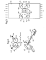
- a test machine shown generally at 10 has a load frame 12. Pillars 14 support a first hydraulic actuator 16 and a first load cell 18, and a pair of grips 20. Further structure 22 supports second hydraulic actuators 24, second load cells 26 and a pair of loading bars 28. Each loading bar 28 has a hole 30 near its end, into which a pin (not shown) can be fitted.
- a fixture 38 is securely held between the grips 20 of the testing machine 10.
- the fixture 38 has two recesses 39 matching the profile of the disc slots whose behaviour is to be reproduced.
- Two test specimens 36 have, at one end, a mounting feature 37 matching the profile of the blade whose behaviour is to be reproduced and, at the other end, a suitable hole permitting pin attachment of the test specimens 36 to the loading bars 28, in the conventional manner.
- the first actuator 16 applies a load to the fixture 38.
- the applied load is measured by the first load cell 18.
- This loading represents the hoop stress in the disc, in the real component.
- the second actuators 24 apply loads to the test specimens 36. These loads are measured by the second load cells 26. These loads represent the centripetal loading of the rotor blades, in the real component.
- the second actuators 24 are mounted on a floating carriage, supported on springs 32 (only one shown). These support the weight of the carriage, while permitting limited vertical movement. This permits the second actuators 24 to apply their loads without introducing undesired bending, even though the fixture 38 will move up and down slightly during the test as the load applied by the first actuator 16 decreases and increases.
- the actuators 16 and 24 are controlled by a computer 48, which receives information from the load cells 18 and 26, via controllers 46, and sends controlling signals 50 to the actuators.
- HCF shaker 40 Attached to each test specimen 36 is an HCF shaker 40.
- HCF shaker 40 is attached to, but vibrationally isolated from, the load frame 12 by a spring 42.
- the load applied by the HCF shaker 40 represents the mechanical and aerodynamic vibrations in the blade, in the real component.
- FIG. 2 illustrates the principles of operation of the HCF shaker 40.
- two intermeshing gear wheels 62 are mounted within the casing 60 of the shaker 40. Attached to each gear wheel 62, at a distance r from its centre, is an eccentric mass 64 of m/2. The angular disposition of the masses is as shown in the drawing, so that the assembly is symmetrical about a central vertical axis.
- a periodic reciprocating force F is set up, as shown by the arrow 72.
- the motor 66 and the clutch/brake 68 are controlled by signals 50 from the computer 48.
- strain gauges 80 are mounted on the fixture (one is invisible behind the fixture).
- FIG. 3 shows the loading applied to the fixture 38, both directly and as a result of the mating test specimens 36.
- the load D on the fixture is set such that the relative sliding displacement, between the test specimen and the fixture, matches that in the real component, as determined from three-dimensional finite element (FE) modelling.
- the load D is then varied, such that the strain, measured at the disc slot bottom, remains constant.As the test progresses, wear of the coating leads to an increase in the friction coefficient ⁇ on the dovetail contact flank 78. The blade specimen will slide out of the disc slot until limiting friction F is reached (as shown by the arrows 82).
- the width L of the fixture ligament 86 is designed such that the slot-bottom strain is sensitive to friction (for example a drop in strain of 30% would be achieved by going from 0.1 to 0.7 friction coefficient), whilst still ensuring the disc ligament 86 is stiff enough to prevent any alignment / bending problems for the rig. This is unlike the real component which is relatively stiff and insensitive to friction.
- Finite Element (FE) analyses of the real fan blade and disc, and the bi-axial rig configuration, are required to define the test regime.
- these analyses cover the full range of friction levels likely to be seen, both in the real component and in the rig test. It is important that the same FE modelling standard (i.e. contact definition, friction level, element type, mesh density etc.) is used for both the specimen and real blade/disc analyses. This ensures that both stress level and relative sliding displacement can be accurately predicted.
- test conditions Four basic parameters are required to set test conditions. These are:
- strain gauges typically 12 strain gauges are applied, four on each test specimen (not shown) and four on the fixture ligament (as shown in Figure 3). These are used to ensure alignment of the rig, as well as ensuring the desired test conditions are achieved. The output of the strain gauges is recorded continuously during the test for later analysis.
- test specimen mounting features 37 may be representative of a firtree root or any other conventional blade mounting feature.
- the HCF load may be applied by hydraulic means rather than by the mechanical arrangement described.
- a furnace or other heating means may be provided so that testing may be performed at elevated temperature.
- the strain measurement, either in the fixture ligament or in the test specimens, may be by contacting or non-contacting extensometry rather than by strain gauges.
Landscapes
- Physics & Mathematics (AREA)
- Health & Medical Sciences (AREA)
- Life Sciences & Earth Sciences (AREA)
- Chemical & Material Sciences (AREA)
- Analytical Chemistry (AREA)
- Biochemistry (AREA)
- General Health & Medical Sciences (AREA)
- General Physics & Mathematics (AREA)
- Immunology (AREA)
- Pathology (AREA)
- Investigating Strength Of Materials By Application Of Mechanical Stress (AREA)
Abstract
Description
Claims (14)
- A method of simulating life of a rotor blade mounting feature mounted in a complementary rotor disc mounting feature, comprising the steps ofproviding two specimen mounting features (37) each having portions defining pressure faces matching in profile respective faces of the rotor blade mounting feature;providing a fixture (38) having two opposed mounting features (39) each having portions defining pressure faces (78) matching in profile respective faces of the rotor disc mounting feature;mounting the specimen mounting features (37) in the fixture mounting features (39);applying a first load to the specimen mounting features (37);measuring a strain in a region (86) of the fixture (38) between the fixture mounting features (39);applying a second load to the fixture (38), the second load being substantially perpendicular to the first load;controlling the second load in response to the measured strain.
- A method as claimed in claim 1, further comprising the step ofapplying a high cycle load to the specimen mounting features (37).
- A method as claimed in claim 1 or claim 2, in which the measured strain is in the same direction as the second load.
- A method as claimed in any preceding claim, in which the second load is controlled to keep the measured strain substantially constant.
- A method as claimed in any preceding claim, in which the measured strain at a given time can be related to the coefficient of friction between the respective pressure faces of the specimen mounting features (37) and the fixture mounting features (39) at that time.
- A method as claimed in claim 5, in which the strain-friction relationship is derived using FE modelling techniques.
- An apparatus (10) for simulating life of a rotor blade mounting feature mounted in a complementary rotor disc mounting feature, comprisingtwo specimen mounting features (37) each having portions defining pressure faces matching in profile respective faces of the rotor blade mounting feature;a fixture (38) having two opposed mounting features (39) each having portions defining pressure faces (78) matching in profile respective faces of the rotor disc mounting feature, the specimen mounting features (37) being mounted in the fixture mounting features (39);means (24) for applying a first load to the specimen mounting features (37);means for measuring a strain in a region (86) of the fixture (38) between the fixture mounting features (39);means (16) for applying a second load to the fixture (38), the second load being substantially perpendicular to the first load;means for controlling the second load in response to the measured strain.
- An apparatus (10) as claimed in claim 7, in which means (40) are provided for applying high cycle loads to the specimen mounting features (37).
- An apparatus as claimed in claim 8, in which the means (40) for applying high cycle loads comprise mechanical means or hydraulic means.
- An apparatus (10) as claimed in any of claims 7 to 9, in which the region (86) of the fixture (38) between the fixture mounting features (39) is designed to achieve an optimal balance between strain sensitivity and rigidity.
- An apparatus (10) as claimed in any of claims 7 to 10, in which the strain measurement means comprise strain gauges (80), contacting extensometry or non-contacting extensometry.
- An apparatus (10) as claimed in any of claims 7 to 11, in which the strain measurement means are also used to indicate misalignment.
- An apparatus (10) as claimed in any of claims 7 to 12, in which strain measurement means are provided on the specimen mounting features (37).
- An apparatus (10) as claimed in any of claims 7 to 13, in which means are provided to heat at least the specimen mounting features (37).
Applications Claiming Priority (2)
| Application Number | Priority Date | Filing Date | Title |
|---|---|---|---|
| GBGB0410967.4A GB0410967D0 (en) | 2004-05-17 | 2004-05-17 | An apparatus and method for fatigue testing |
| GB0410967 | 2004-05-17 |
Publications (3)
| Publication Number | Publication Date |
|---|---|
| EP1598655A2 true EP1598655A2 (en) | 2005-11-23 |
| EP1598655A3 EP1598655A3 (en) | 2006-05-31 |
| EP1598655B1 EP1598655B1 (en) | 2008-03-26 |
Family
ID=32527175
Family Applications (1)
| Application Number | Title | Priority Date | Filing Date |
|---|---|---|---|
| EP05252280A Ceased EP1598655B1 (en) | 2004-05-17 | 2005-04-12 | An apparatus and method for fatigue testing |
Country Status (4)
| Country | Link |
|---|---|
| US (1) | US7204152B2 (en) |
| EP (1) | EP1598655B1 (en) |
| DE (1) | DE602005005550T2 (en) |
| GB (1) | GB0410967D0 (en) |
Cited By (6)
| Publication number | Priority date | Publication date | Assignee | Title |
|---|---|---|---|---|
| FR2927998A1 (en) * | 2008-02-25 | 2009-08-28 | Snecma Sa | TESTING MACHINE FOR A WAVE FOOT COATING. |
| FR2927997A1 (en) * | 2008-02-25 | 2009-08-28 | Snecma Sa | METHOD FOR TESTING A WAVE FOOT COATING |
| US7624648B2 (en) | 2007-06-26 | 2009-12-01 | Bose Corporation | System and method for multi-axes simulation |
| US8505388B2 (en) | 2009-04-15 | 2013-08-13 | Rolls-Royce, Plc | Apparatus and method for simulating lifetime of and/or stress experienced by a rotor blade and rotor disc fixture |
| US8650961B2 (en) | 2010-01-27 | 2014-02-18 | Rolls-Royce Plc | Apparatus for generating vibrations in a component |
| CN110718123A (en) * | 2019-10-10 | 2020-01-21 | 常州大学 | Non-metal rod piece stretch bending combined deformation experiment platform |
Families Citing this family (29)
| Publication number | Priority date | Publication date | Assignee | Title |
|---|---|---|---|---|
| US7668769B2 (en) * | 2005-10-04 | 2010-02-23 | Basepoint Analytics, LLC | System and method of detecting fraud |
| SE528669C2 (en) * | 2006-02-09 | 2007-01-16 | Scania Cv Abp | Method is for preparation of test piece for use in durability test of engine block which contains cylindrical hollow formations separated from each other by intermediate walls |
| US20080257057A1 (en) * | 2006-09-29 | 2008-10-23 | Habeger Jason A | Device for fatigue testing an implantable medical device |
| CN100543449C (en) * | 2007-02-15 | 2009-09-23 | 厦门金藏机电有限公司 | Detecting instrument for alloy saw blade welding strength |
| US8214104B2 (en) * | 2007-04-17 | 2012-07-03 | Kabushiki Kako Co., Ltd. | Abnormal noise inspection method for anti-vibration device for vehicle use |
| WO2008134591A2 (en) * | 2007-04-25 | 2008-11-06 | Fujikura Composite America, Inc. | Method and apparatus for testing shafts |
| EP2162721B1 (en) * | 2007-05-30 | 2019-10-30 | Vestas Wind Systems A/S | Method of testing wind turbine blades |
| US8291589B2 (en) * | 2007-08-08 | 2012-10-23 | United Technologies Corporation | Method for establishing a location of an elevated stress region |
| CN101660990B (en) * | 2008-08-25 | 2012-08-22 | 中国船舶重工集团公司第七0三研究所 | Slight impact wear test machine |
| US7971491B2 (en) * | 2009-03-09 | 2011-07-05 | The Boeing Company | Apparatus and method for transverse tensile strength testing of materials at extreme temperatures |
| GB2489263A (en) * | 2011-03-23 | 2012-09-26 | Rolls Royce Plc | Device for fatigue testing a specimen |
| US8688418B2 (en) * | 2011-09-01 | 2014-04-01 | Mcmoran Oil & Gas, Llc | Engineered methodology for design verification and validation of ultra-deep high pressure high temperature oil and gas well control equipment |
| CN102519791B (en) * | 2011-12-13 | 2013-07-31 | 河海大学 | Mechanical fatigue tester for test piece |
| WO2015176742A1 (en) * | 2014-05-20 | 2015-11-26 | Shell Internationale Research Maatschappij B.V. | Method for qualification testing of a tubular connector |
| US10067077B2 (en) * | 2014-08-18 | 2018-09-04 | PulseRay Inc. | Rotational and axial motion system and methods of use |
| US9823159B2 (en) * | 2015-03-16 | 2017-11-21 | Dmar Engineering, Inc. | Low cycle fatigue testing |
| KR101807589B1 (en) * | 2016-02-05 | 2018-01-18 | 두산중공업 주식회사 | Fatigue testing machine for measuring fatigue of the connection of the blades and the rotor disc specimen sample. |
| US10324000B2 (en) * | 2016-12-21 | 2019-06-18 | The Boeing Company | Test fixture for tensioning and cooling an article |
| US10746640B2 (en) * | 2017-03-21 | 2020-08-18 | Textron Innovations Inc. | Methods of making a tubular specimen with a predetermined wrinkle defect |
| US10744727B2 (en) | 2017-03-21 | 2020-08-18 | Textron Innovations Inc. | Methods of making a specimen with a predetermined wrinkle defect |
| US10635813B2 (en) | 2017-10-06 | 2020-04-28 | Sophos Limited | Methods and apparatus for using machine learning on multiple file fragments to identify malware |
| US11003774B2 (en) | 2018-01-26 | 2021-05-11 | Sophos Limited | Methods and apparatus for detection of malicious documents using machine learning |
| US11941491B2 (en) | 2018-01-31 | 2024-03-26 | Sophos Limited | Methods and apparatus for identifying an impact of a portion of a file on machine learning classification of malicious content |
| US11270205B2 (en) | 2018-02-28 | 2022-03-08 | Sophos Limited | Methods and apparatus for identifying the shared importance of multiple nodes within a machine learning model for multiple tasks |
| WO2020030913A1 (en) | 2018-08-07 | 2020-02-13 | Sophos Limited | Methods and apparatus for management of a machine-learning model to adapt to changes in landscape of potentially malicious artifacts |
| US11947668B2 (en) | 2018-10-12 | 2024-04-02 | Sophos Limited | Methods and apparatus for preserving information between layers within a neural network |
| US11574052B2 (en) | 2019-01-31 | 2023-02-07 | Sophos Limited | Methods and apparatus for using machine learning to detect potentially malicious obfuscated scripts |
| US12010129B2 (en) | 2021-04-23 | 2024-06-11 | Sophos Limited | Methods and apparatus for using machine learning to classify malicious infrastructure |
| CN118776791B (en) * | 2024-07-19 | 2025-11-21 | 北京航空航天大学 | Micro-abrasion test scheme for tenon connection structure under blade vibration |
Family Cites Families (16)
| Publication number | Priority date | Publication date | Assignee | Title |
|---|---|---|---|---|
| DE1950917A1 (en) * | 1969-10-09 | 1971-04-29 | Goetzewerke | Testing device |
| FR2368029A1 (en) * | 1976-10-15 | 1978-05-12 | Onera (Off Nat Aerospatiale) | Stress and fatigue test rig - has motors producing oscillatory forces in two perpendicular directions |
| SU966532A1 (en) | 1981-04-08 | 1982-10-15 | Малоярославецкий Филиал Государственного Всесоюзного Ордена Трудового Красного Знамени Научно-Исследовательского Технологического Института Ремонта И Эксплуатации Машинно-Тракторного Парка И Центрального Опытно-Конструкторского Технологического Бюро | Stand for testing vehicle steering knuckle |
| US4478086A (en) * | 1983-01-07 | 1984-10-23 | Mts Systems Corporation | Load frame crosshead construction |
| GB9017887D0 (en) * | 1990-08-15 | 1990-09-26 | Maddison Anthony | Stressing device |
| GB9319788D0 (en) | 1993-09-24 | 1993-11-10 | Instron Ltd | Structure testing machine |
| AU6330898A (en) * | 1997-02-21 | 1998-09-09 | Southwest Research Institute | High-cycle fatigue test machine |
| DE19726769C1 (en) * | 1997-06-24 | 1999-02-25 | Mannesmann Sachs Ag | Oscillation damper damping force testing device |
| US6247370B1 (en) * | 1999-01-25 | 2001-06-19 | Council Of Scientific And Industrial Research | Two dimensional stress relaxation testing device |
| US6250166B1 (en) * | 1999-06-04 | 2001-06-26 | General Electric Company | Simulated dovetail testing |
| GB0019434D0 (en) * | 2000-08-09 | 2000-09-27 | Rolls Royce Plc | A device and method for fatigue testing of materials |
| US6718833B2 (en) * | 2001-03-05 | 2004-04-13 | Adtech Systems Research, Inc. | Multiaxial high cycle fatigue test system |
| US6601456B1 (en) * | 2001-06-06 | 2003-08-05 | Southwest Research Institute | Fretting fixture for high-cycle fatigue test machines |
| AU2002320247A1 (en) | 2002-07-03 | 2004-01-23 | Midwest Research Institute | Resonance test system |
| US6813960B1 (en) * | 2002-08-19 | 2004-11-09 | Southwest Research Institute | Asymmetrical column assembly for high-cycle fatigue test machines |
| US6848311B1 (en) * | 2004-02-09 | 2005-02-01 | The United States Of America As Represented By The Secretary Of The Navy | Method for estimating the properties of a solid material subjected to compressional forces |
-
2004
- 2004-05-17 GB GBGB0410967.4A patent/GB0410967D0/en not_active Ceased
-
2005
- 2005-04-12 DE DE602005005550T patent/DE602005005550T2/en not_active Expired - Lifetime
- 2005-04-12 EP EP05252280A patent/EP1598655B1/en not_active Ceased
- 2005-04-13 US US11/104,486 patent/US7204152B2/en not_active Expired - Lifetime
Cited By (12)
| Publication number | Priority date | Publication date | Assignee | Title |
|---|---|---|---|---|
| US7624648B2 (en) | 2007-06-26 | 2009-12-01 | Bose Corporation | System and method for multi-axes simulation |
| JP2010532002A (en) * | 2007-06-26 | 2010-09-30 | ボーズ・コーポレーション | Multi-axis simulation system and method |
| FR2927998A1 (en) * | 2008-02-25 | 2009-08-28 | Snecma Sa | TESTING MACHINE FOR A WAVE FOOT COATING. |
| FR2927997A1 (en) * | 2008-02-25 | 2009-08-28 | Snecma Sa | METHOD FOR TESTING A WAVE FOOT COATING |
| WO2009112757A1 (en) * | 2008-02-25 | 2009-09-17 | Snecma | Device for testing the coating of a vane base |
| WO2009112756A1 (en) * | 2008-02-25 | 2009-09-17 | Snecma | Method for testing the coating of a vane base |
| JP2011513700A (en) * | 2008-02-25 | 2011-04-28 | スネクマ | How to test vane base coatings |
| US8387467B2 (en) | 2008-02-25 | 2013-03-05 | Snecma | Method for testing the coating of a vane base |
| US8408068B2 (en) | 2008-02-25 | 2013-04-02 | Snecma | Device for testing the coating of a vane base |
| US8505388B2 (en) | 2009-04-15 | 2013-08-13 | Rolls-Royce, Plc | Apparatus and method for simulating lifetime of and/or stress experienced by a rotor blade and rotor disc fixture |
| US8650961B2 (en) | 2010-01-27 | 2014-02-18 | Rolls-Royce Plc | Apparatus for generating vibrations in a component |
| CN110718123A (en) * | 2019-10-10 | 2020-01-21 | 常州大学 | Non-metal rod piece stretch bending combined deformation experiment platform |
Also Published As
| Publication number | Publication date |
|---|---|
| DE602005005550D1 (en) | 2008-05-08 |
| GB0410967D0 (en) | 2004-06-16 |
| EP1598655B1 (en) | 2008-03-26 |
| US20050252304A1 (en) | 2005-11-17 |
| DE602005005550T2 (en) | 2008-06-26 |
| US7204152B2 (en) | 2007-04-17 |
| EP1598655A3 (en) | 2006-05-31 |
Similar Documents
| Publication | Publication Date | Title |
|---|---|---|
| EP1598655B1 (en) | An apparatus and method for fatigue testing | |
| EP1602914B1 (en) | An apparatus and a method for testing attachment features of components | |
| US6250166B1 (en) | Simulated dovetail testing | |
| Panning et al. | Asymmetrical underplatform dampers in gas turbine bladings: theory and application | |
| EP2241872A2 (en) | Apparatus and method for simulating lifetime of and/or stress experienced by a rotor blade and rotor disc fixture | |
| EP2503317B1 (en) | Device for fatigue testing a specimen | |
| GB2367631A (en) | Device and method for fatigue testing a specimen | |
| Bessone et al. | Investigation on the dynamic response of blades with asymmetric under platform dampers | |
| CN101960284B (en) | Device for testing the coating of a vane base | |
| Kielb et al. | Experimental study of aerodynamic and structural damping in a full-scale rotating turbine | |
| Padova et al. | Casing treatment and blade-tip configuration effects on controlled gas turbine blade tip/shroud rubs at engine conditions | |
| CN120063700A (en) | Micro fatigue life test device and method under high-temperature and high-frequency vibration conditions considering surface integrity | |
| Marquina et al. | Friction damping modeling in high stress contact areas using microslip friction model | |
| GB2472193A (en) | Rotor blade test specimen | |
| CN118150380A (en) | Device and method for dynamically measuring fretting fatigue friction coefficient | |
| Umehara et al. | New modeling combining kinematic and stiffness nonlinearity in under platform dampers | |
| Almeida | Experiments, modelling and analysis of fretting fatigue for Inconel 718 and Ti-6Al-4V under time-varying contact normal load at room and high temperature | |
| Simmons et al. | Effects of stator flow distortion on rotating blade endurance: Part 2—Stress analysis and failure criteria | |
| Armstrong et al. | Paper 14: Fatigue Life of Compressor Blading | |
| JP4673792B2 (en) | Gas turbine component life management system and gas turbine component life management method | |
| Macdonald | An investigation of the damage mechanisms occurring during compressor blade rubbing | |
| CN121453355A (en) | Method for judging influence factors of damping ratio of multi-contact-surface combined rotor assembly | |
| Shorr et al. | Numerical and experimental estimation of the turbine blade damper efficiency | |
| WO2025111309A1 (en) | Portable accelerated fatigue testing system | |
| Mankowski | Internal damping characteristics of a mine hoist cable undergoing non-planar transverse vibration |
Legal Events
| Date | Code | Title | Description |
|---|---|---|---|
| PUAI | Public reference made under article 153(3) epc to a published international application that has entered the european phase |
Free format text: ORIGINAL CODE: 0009012 |
|
| AK | Designated contracting states |
Kind code of ref document: A2 Designated state(s): AT BE BG CH CY CZ DE DK EE ES FI FR GB GR HU IE IS IT LI LT LU MC NL PL PT RO SE SI SK TR |
|
| AX | Request for extension of the european patent |
Extension state: AL BA HR LV MK YU |
|
| PUAL | Search report despatched |
Free format text: ORIGINAL CODE: 0009013 |
|
| AK | Designated contracting states |
Kind code of ref document: A3 Designated state(s): AT BE BG CH CY CZ DE DK EE ES FI FR GB GR HU IE IS IT LI LT LU MC NL PL PT RO SE SI SK TR |
|
| AX | Request for extension of the european patent |
Extension state: AL BA HR LV MK YU |
|
| 17P | Request for examination filed |
Effective date: 20060426 |
|
| AKX | Designation fees paid |
Designated state(s): DE FR GB |
|
| GRAP | Despatch of communication of intention to grant a patent |
Free format text: ORIGINAL CODE: EPIDOSNIGR1 |
|
| GRAS | Grant fee paid |
Free format text: ORIGINAL CODE: EPIDOSNIGR3 |
|
| GRAA | (expected) grant |
Free format text: ORIGINAL CODE: 0009210 |
|
| AK | Designated contracting states |
Kind code of ref document: B1 Designated state(s): DE FR GB |
|
| REG | Reference to a national code |
Ref country code: GB Ref legal event code: FG4D |
|
| REF | Corresponds to: |
Ref document number: 602005005550 Country of ref document: DE Date of ref document: 20080508 Kind code of ref document: P |
|
| ET | Fr: translation filed | ||
| PLBE | No opposition filed within time limit |
Free format text: ORIGINAL CODE: 0009261 |
|
| STAA | Information on the status of an ep patent application or granted ep patent |
Free format text: STATUS: NO OPPOSITION FILED WITHIN TIME LIMIT |
|
| 26N | No opposition filed |
Effective date: 20081230 |
|
| REG | Reference to a national code |
Ref country code: FR Ref legal event code: PLFP Year of fee payment: 11 |
|
| REG | Reference to a national code |
Ref country code: FR Ref legal event code: PLFP Year of fee payment: 12 |
|
| REG | Reference to a national code |
Ref country code: FR Ref legal event code: PLFP Year of fee payment: 13 |
|
| REG | Reference to a national code |
Ref country code: FR Ref legal event code: PLFP Year of fee payment: 14 |
|
| PGFP | Annual fee paid to national office [announced via postgrant information from national office to epo] |
Ref country code: DE Payment date: 20210628 Year of fee payment: 17 Ref country code: FR Payment date: 20210427 Year of fee payment: 17 |
|
| PGFP | Annual fee paid to national office [announced via postgrant information from national office to epo] |
Ref country code: GB Payment date: 20210426 Year of fee payment: 17 |
|
| REG | Reference to a national code |
Ref country code: DE Ref legal event code: R119 Ref document number: 602005005550 Country of ref document: DE |
|
| GBPC | Gb: european patent ceased through non-payment of renewal fee |
Effective date: 20220412 |
|
| PG25 | Lapsed in a contracting state [announced via postgrant information from national office to epo] |
Ref country code: GB Free format text: LAPSE BECAUSE OF NON-PAYMENT OF DUE FEES Effective date: 20220412 Ref country code: FR Free format text: LAPSE BECAUSE OF NON-PAYMENT OF DUE FEES Effective date: 20220430 Ref country code: DE Free format text: LAPSE BECAUSE OF NON-PAYMENT OF DUE FEES Effective date: 20221103 |